


-
Wind resource has the advantages of higher wind speed, stable propagation direction, lower turbulence intensity, and free surface roughness in the far-reaching sea[1]. With the exhaustion of shallow wind power resources, exploring offshore wind power towards deeper and farther ocean areas is of great interest. Due to the dramatically increased costs and limitations about the maximum operational depth of wind turbine installation vessels, the traditional fixed foundation may no longer be feasible for sea areas with a water depth greater than 60 m. The floating offshore wind turbine (FOWT) seems to be a feasible solution for the development of wind power in the deep sea. In 2017, Hywind Scotland, the world's first commercial floating wind power project, was officially put into operation in Scotland[2]. By the end of 2020, the wind power generation of FOWTs around the world has reached 125 MW[3]. In recent years, engineering and academia around the world have put forward various forms of foundations for FOWTs[4]. The FOWTs have many advantages, for example, it is not limited by water depth and geological conditions, is easy to dismantle, has little impact on the environment, and is suitable for high-power wind turbine[5]. On the other hand, it can be wet towed to the installation sites through self-floating, which is another significant advantage of the FOWTs.
For the wet towing performance of marine structures, scholars have carried out a few researches that mainly focus on the stability of towing system and towing resistance. Strandhangen et al.[6-7] studied the towing system based on linear theory and found that changing the towing point's frequency and the towing line length could make the towing system have better stability. Inoue et al.[8] used the linear theory to study the course stability of towing system under multiple tugboats and found that the elasticity of the towing line and the weight of the object being towed had a great influence on the course stability of the towing system. Bernitsaa et al.[9] analyzed the influence of elastic streamers on the stability of towing. Varyani et al.[10] carried out a numerical simulation on towing operation of the damaged ships and pointed out that wind load was the main factor affecting the stability of towing system. FOWTs have a high center of gravity and are subjected to complicated environmental loads such as wind, waves, and current in addition to the towing force during the transport phase. How to ensure the safety of transportation for FOWTs is one of the urgent problems to be addressed. In recent years, scholars have carried out preliminary research on the towing operation process for FOWTs with different types of foundations. Collu et al.[11] studied the static stability criterion of the towing process of FOWT under normal and severe environments, and provided the calculation guidelines for the maximum values of the metacentric height and the maximum height of the towing lines, then applied the results to design the semi-submersible floating foundation for NOVA FOWT to evidence the overall good performance of these rules. Adam et al.[12-13] experimented to study the towing stability of the GICON®-TLP under two different carriage speeds in calm water and two different regular wave conditions. Two different configurations including a squared configuration and a diagonal configuration of the GICON®-TLP were performed to determine which configuration had a lower resistance and a better seakeeping performance. The results showed that the towing speed and wave height significantly influenced the stability and towing resistance. The diagonal configuration had a lower resistance than the squared configuration because the truss structure of the squared configuration had no hydrodynamic permeability. Moreover, the non-stationary flow which detachment at the cylindrical buoyancy bodies would generate an oscillating sway motion. Ding et al.[14] designed a submerged floating foundation for supporting an NREL 5 MW wind turbine and researched the dynamic response of the SFOWT in complex environmental conditions. Han et al.[15] put forward a towing system model of the SFOWT based on multi-body dynamics theory to study the wind, wave, current, and height of towing point on the motion response of the SFOWT during towing phase. The results showed that under the standard environmental conditions, the inclination of the SFOWT met the requirements of the standard that the absolute acceleration of heave was less than 0.2 g, but the viscous damping of the SFOWT did not consider in the towing analysis. Le et al.[16] analyzed the four SFOWTs exhibited good performance under both conditions and the effect of wind-wave misalignment under extreme conditions. Zhang et al.[17] analyzed the influence of the subdivision structure on the towing resistance of the CBF and compared it with the tow test in hydrostatic water. Büttner et al.[18] examined the influence of wave direction, and a range of model orientations towards the incident waves were tested in still water and together with the simulated towing state.
Therefore, physical model tests of both TC-SFOWT and FC-SFOWT structures were carried out to study the inherent periods of the two structure types and carry out the hydrostatic, regular wave, and irregular wave towing tests to investigate the effect of wave height, period, and towing point height on the acceleration, longitudinal rocking, transverse rocking, and towing force under fixed water depth.
-
During the SFOWT whole machine towing test, it is necessary to ensure that the test model and prototype meet the similarity criteria, including geometric similarity, motion similarity, and dynamic similarity.
1) Geometric similarity
When making the TC-SFOWT or FC-SFOWT test models, it is necessary to scale the prototype according to the similarity ratio, and it is necessary to ensure that the shape of the model is completely similar to the prototype. In addition, the environmental water depth, wind, wave and current elements, and other conditions involved in the model test also need to be compared with the same physical quantities of the actual sea state according to the similarity ratio. The similar ratio in the experiment is $\lambda {\text{ = }}1:80$.
$$ \lambda = {L_{\rm{m}}}/{L_{\rm{p}}} $$ (1) 2) Motion similarity
Models and prototypes are similar to Fr (Froude number) and St (Strouhal number). The Fr equally guarantees the correct similar relationship between the inertia and gravity of the model and the prototype. The St is equally guaranteed that the movement and force of the floating fan of the entire machine trailer under the wavy load can present periodic changes. The expressions of Fr and St are shown below.
$$ {F_{\rm{r}}} = {V_{\rm{p}}}/\sqrt {g{L_{\rm{p}}}} = {V_{\rm{m}}}/\sqrt {g{L_{\rm{m}}}} $$ (2) $$ {S_{\rm{t}}} = {L_{\rm{p}}}/{V_{\rm{p}}}T = {L_{\rm{m}}}/{V_{\rm{m}}}{T_{\rm{m}}} $$ (3) 3) Power similarity
Power similarity means that the model and prototype are under the same conditions, the ratio of the same force in the same position is the fixed value, and the direction is the same. Including gravity G, viscous T, pressure p, inertial force i, etc. The expression is shown below.
$$ {S_{\rm{F}}} = \frac{{{F_{\rm{m}}}}}{{{F_{\rm{p}}}}} = \frac{{{G_{\rm{m}}}}}{{{G_{\rm{p}}}}} = \frac{{{T_{\rm{m}}}}}{{{T_{\rm{p}}}}} = \frac{{{P_{\rm{m}}}}}{{{P_{\rm{p}}}}} = \frac{{{I_{\rm{m}}}}}{{{I_{\rm{p}}}}} $$ (4) In the formula, G is the acceleration of gravity. L, V, and T respectively represent length, speed, and period, respectively. The bids p and m represent the prototype and model, respectively. Table 1 shows a similar relationship between the SFOWT prototype and the model.
Project Symbol Ratio Project Symbol Ratio Length Lp/Lm λ Period Tp/Tm λ0.5 Angle Φp/Φy 1 Force Fp/Fm λ3 Velocity vp/vm λ0.5 Linear acceleration Ap/Am 1 Angle speed ωp/ωm λ-0.5 Table 1. SFOWT prototype and model similar to the model
-
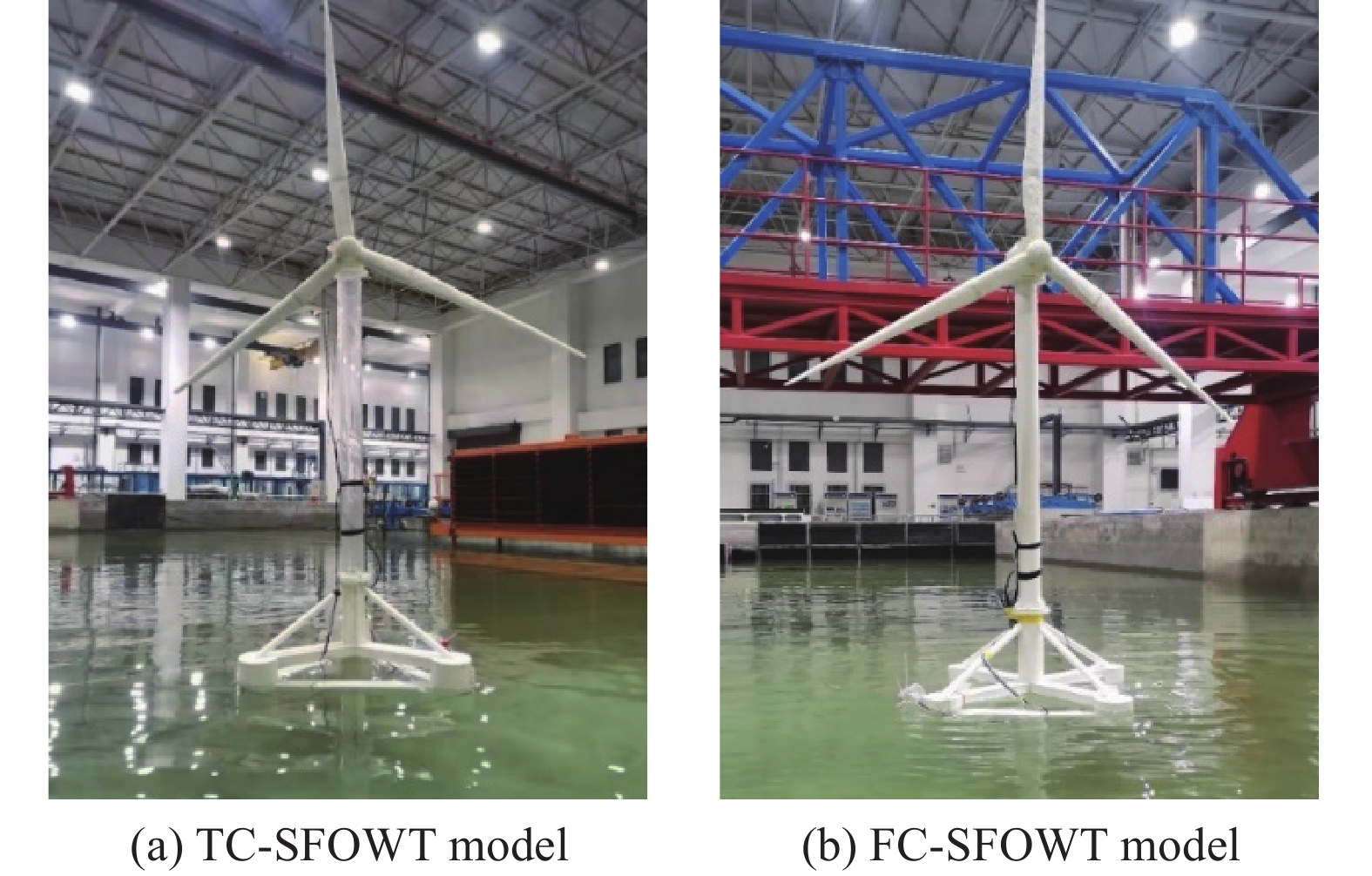
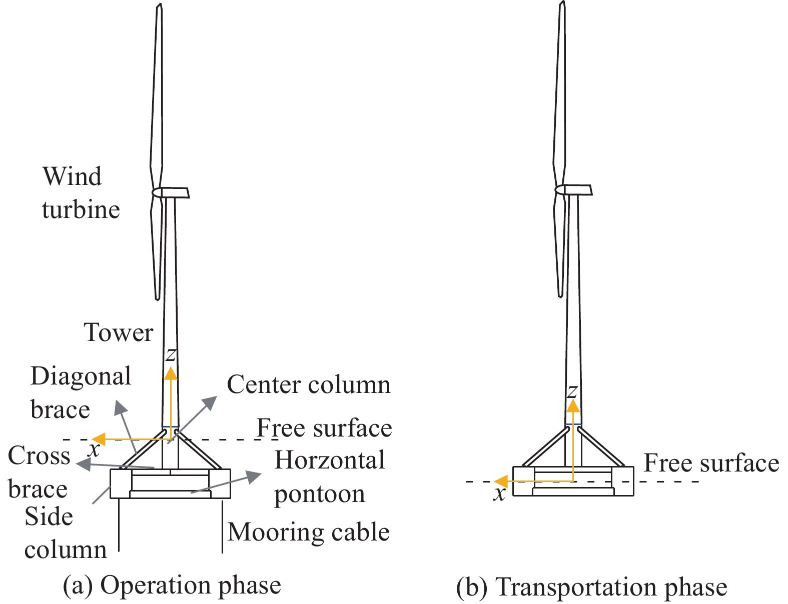
A submerged floating offshore wind turbine (SFOWT) is composed of the upper turbine (DTU 10 MW RWT), tower, and submerged floating foundation, as shown in Fig. 1. The submerged floating foundation is composed of a central column, a vertical float, a horizontal floating tank, and a diagonal brace. The submerged floating foundation has the following structural features. In the bit state, as shown in Fig. 1(a), the wind turbine's foundation is submerged below the water surface under the operation of the tension leg anchorage system. Therefore, it has a relatively small waterline area and is less affected by wave loads, which is SFOWT. In the state of self-floating and towing, as shown in Fig. 1(b), the wind turbine foundation belongs to the semi-submersible platform, which has a large water plane and good stability, and the self-floating towage of SFOWT can be realized by using this advantage.
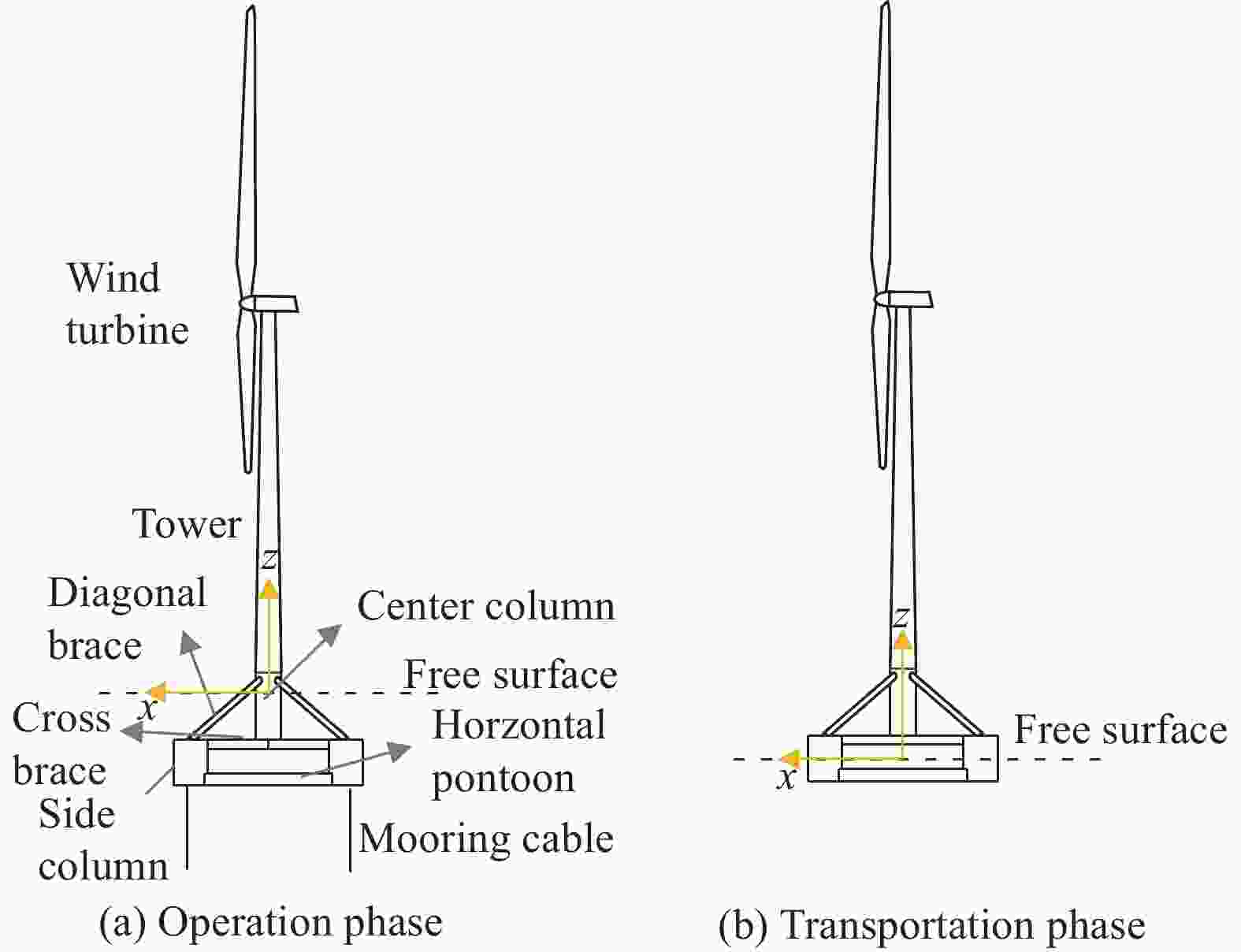
Figure 1. The structure of SFOWT
-
In 2013, the Wind Energy Research Center of the Technical University of Denmark released the model parameters of the wind turbine prototype with a power of 10 MW, called DTU 10 MW RWT[19]. The prototype has the advantages of being lightweight and having high strength of the blade.
The tower of the DTU 10 MW turbine adopts a layered design method, which is divided into 10 sections from the bottom to the top, and the wall thickness of each section remains the same, vary from the bottom diameter to the top diameter. The bottom diameter is 8.3 m (the elevation is 0 m, corresponding to a wall thickness of 38 mm), and the top diameter is 5.5 m (the elevation is 115.63 m, corresponding to a wall thickness of 20 mm).
During the actual towing process, the wind turbines are in a shutdown state, there is no need to consider the rotation of the blade and the aerodynamic load it receives. Therefore, the model of the turbine blade in the test is based on the parameters of the DTU 10 MW turbine blade and is made of hard foam according to the change of its airfoil to ensure that its shape and quality are similar. The main design parameters of the turbine are shown in Table 2. The main design parameters of the turbine blades are given in the paper[20]. According to a similar theory, the tower and the engine room are made of plexiglass.
Project Prototype Model Blade length/m 86.366 1.080 Impeller quality/kg 227 962 0.445 Cabin quality/kg 446 036 0.871 Tower quality/kg 628 442 1.227 Hub height/m 119 1.488 Diameter of impeller/m 178.3 2.229 Table 2. DTU 10 MW turbine prototype and model basic parameters
-
The TC-SFOWT or FC-SFOWT foundation is made of plexiglass, and towing rope is made of steel wire rope and spring. During the production process, the shape and quality of each part are strictly controlled, to ensure that the position of the center of gravity of the SFOWT model is similar to that of the prototype. The basic parameters of the foundation and model are shown in Table 3, the SFOWT model of self-floating state is shown in Fig. 2.
Project TC-SFOWT FC-SFOWT Prototype Model Prototype Model Column diameter/m 8.3 0.104 8.6 0.108 Column height/m 22 0.275 22 0.275 Diameter of float/m 12.68 0.159 11 0.138 Float height/m 15 0.188 15 0.188 Axis distance of float/m 61.24 0.765 50 0.625 Bracing Diameter/m 2 0.025 2 0.025 Basic quality/kg 4.819×10⁶ 8.710 4.812×10⁶ 9.400 Static draft/m 6.0 0.075 5.2 0.065 Table 3. Submerged floating foundation prototype and basic parameters of the model
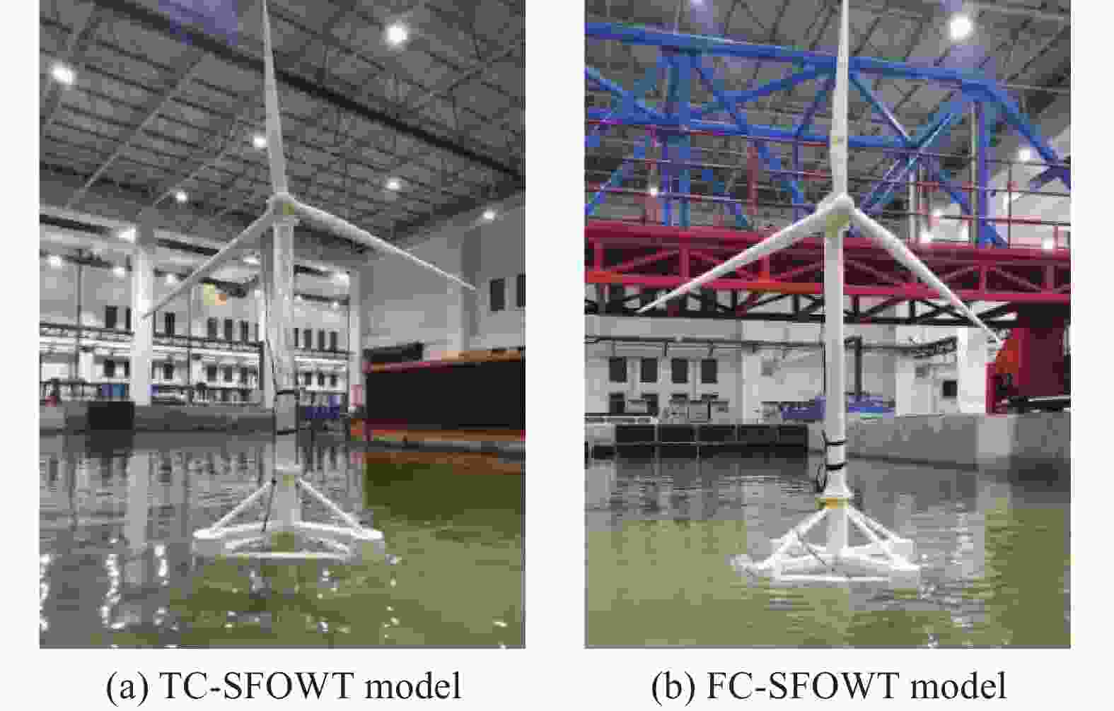
Figure 2. SFOWT towing physical test model
-
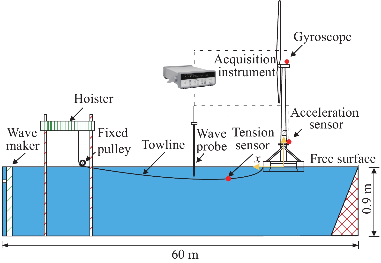
The size of the laboratory pool and the arrangement of sensors are shown in Fig. 3, the test water depth is 0.9 m. During the test, the main focus is on the heave, pitch, roll, and tow cable force response values of SFOWT during the towing process. Choose from three measurement sensors. The inclinometer is used to measure the roll and pitch angles of the SFOWT during towing. The acceleration sensor is used to measure the heave acceleration of the SFOWT during towing. Tension sensors are used to measure the towing force of the SFOWT during towing.

Figure 3. Test tank size and sensor layout
It mainly includes the following three test schemes. Both TC-SFOWT and FC-SFOWT are towed by head sea. Static water-free decay test, the TC-SFOWT, and the FC-SFOWT are released after a certain displacement in the three main degrees of freedom of roll, pitch, and heave respectively, and their motion response time history curves decaying with time were collected. The regular wave towing test is to study the influence of wave height on the dynamic response of each degree of freedom during the SFOWT towing process. Irregular wave towing test uses the Jonswap wave spectrum. During the test, the speed is fixed. According to the test conditions, measure the towed motion response and towing force of SFOWT under the action of irregular waves with different significant wave heights and spectral peak periods, and explore the effect of the height of the towline point on its motion.
-
Carry out the free decay test of TC-SFOWT and FC-SFOWT. The motion time-history curves of the heave, roll, and pitch degrees of freedom are collected and Fourier transformed respectively, to obtain the natural frequencies of TC-SFOWT and FC-SFOWT, the natural periodic frequency of the model test is converted into the natural periodic frequency of the prototype through similarity theory, and compared with the numerical simulation results, as shown in Table 4. From the comparison results, it can be seen that the model test results are in good agreement with the numerical simulation results.
Degrees of freedom Frequency/Hz Numerical Simulation Prototype Relative error Heave TC-SFOWT 0.070 0.073 4.3% FC-SFOWT 0.056 0.057 1.8% Roll TC-SFOWT 0.025 0.027 8.0% FC-SFOWT 0.026 0.028 7.7% Pitch TC-SFOWT 0.024 0.023 4.2% FC-SFOWT 0.026 0.027 3.9% Table 4. Comparison of SFOWT free attenuation frequency numerical simulation and test results
-
Carry out regular wave towing tests to study the influence of wave height and spectral period on the towing performance of SFOWT, the test conditions are shown in Table 5.
Conditions number Wave height/m Wave period/s Model Prototype Model Prototype 1 0.037 5 3.0 1.0 8.9 2 0.050 0 4.0 1.0 8.9 3 0.062 5 5.0 1.0 8.9 4 0.062 5 5.0 1.3 11.6 5 0.062 5 5.0 1.7 15.2 Table 5. Design of regular wave test conditions
Take any 30 s during the towage process for analysis, Fig. 4 and Fig. 5 respectively show the towing time history curve and motion response statistics under the regular wave environment. Research shows that the increase in wave height will obviously increase the response amplitude of each degree of freedom of SFOWT. When the wave height is 6.25 cm, the maximum heave acceleration of the TC-SFOWT is 1.26 m/s2, the maximum pitch is 1.58°, the maximum roll is 1.18°, and the maximum towline force is 3.61 N. The maximum heave acceleration of the FC-SFOWT is 0.97 m/s2, the maximum pitch is 2.27°, the maximum roll is 1.01°, and the maximum towline force is 3.71 N.
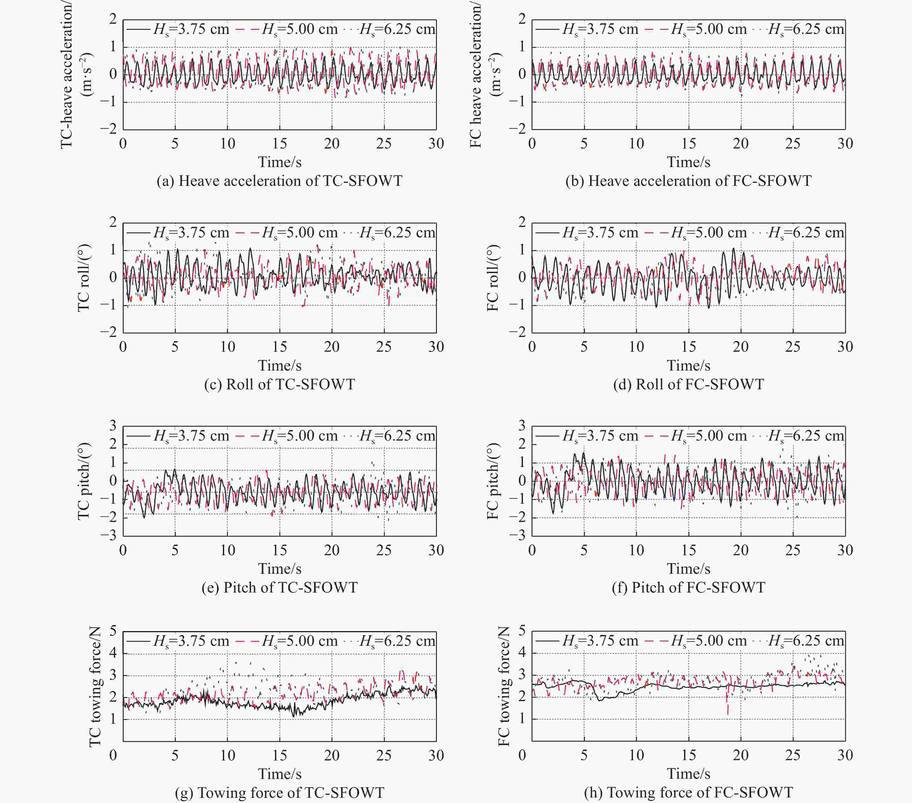
Figure 4. Response time-history curves of SFOWT towing motion at different wave heights (Tp=1.0 s)
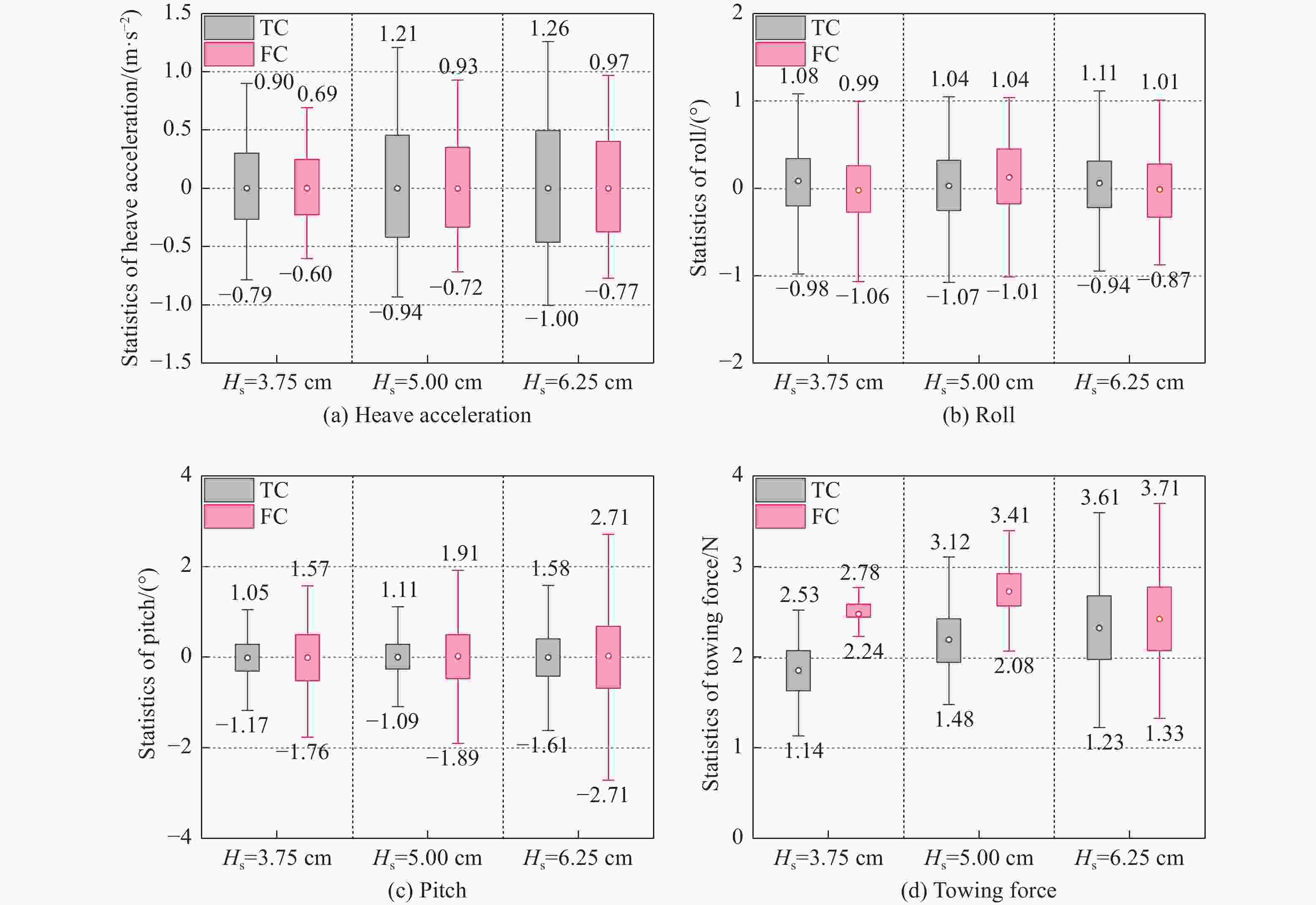
Figure 5. Motion response statistics of the SFOWT under different tow point heights (Tp=1.0 s)
-
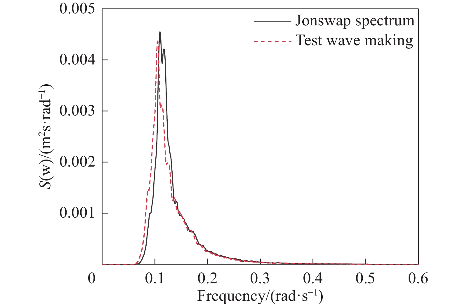
In the towing test of TC-SFOWT and FC-SFOWT in irregular waves, the design sea state has a significant wave height Hs=6.25 cm and a spectral peak period Tp=1.0 s. Fig. 6 shows the comparison results of test wave making and Jonswap spectrum, which are very close, so the test simulation is feasible and reasonable.
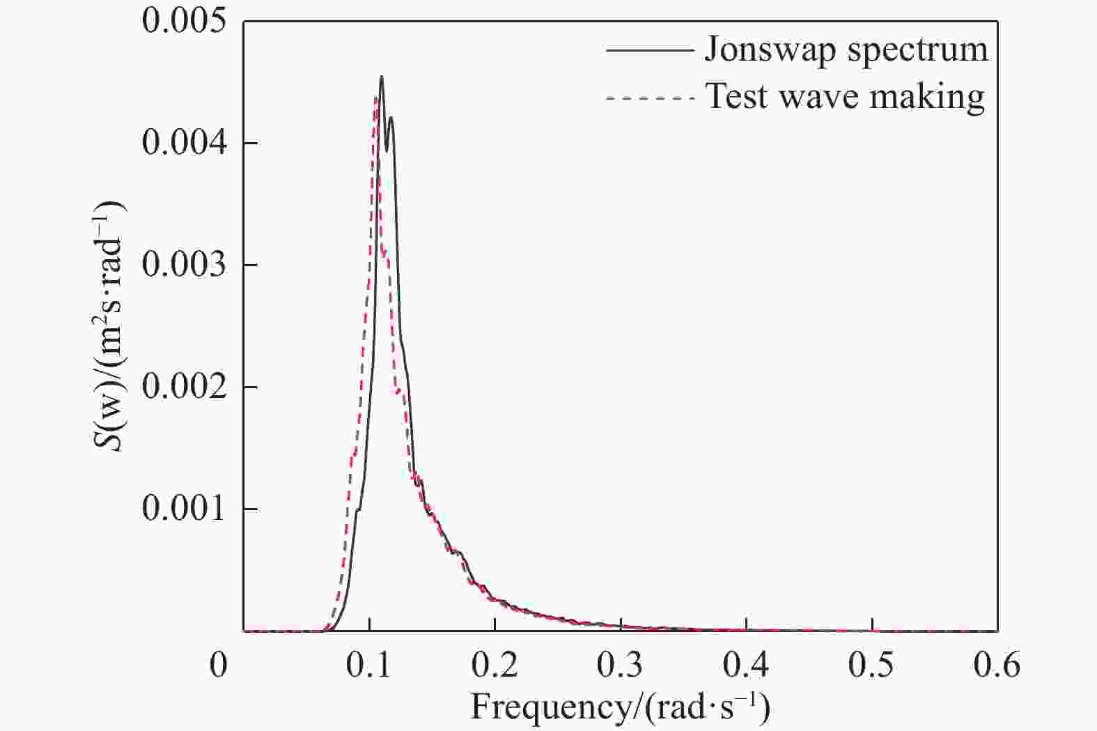
Figure 6. Wave spectrum comparison (Hs=6.25 cm, Tp=1.0 s)
When studying the influence of wave height and period, the height of the towline point is located at the water plane. The tow point height of the TC-SFOWT model is 7.5 cm, and the tow point height of the FC-SFOWT model is 6.5 cm. Table 6 is the design of irregular wave test conditions.
Conditions number Significant wave height (H/m) Peak period (TP/s) Model prototype Model prototype 6 0.0375 3.0 1.0 8.9 7 0.0500 4.0 1.0 8.9 8 0.0625 5.0 1.0 8.9 9 0.0625 5.0 1.3 11.6 10 0.0625 5.0 1.7 15.2 Table 6. Design of irregular wave test conditions
-
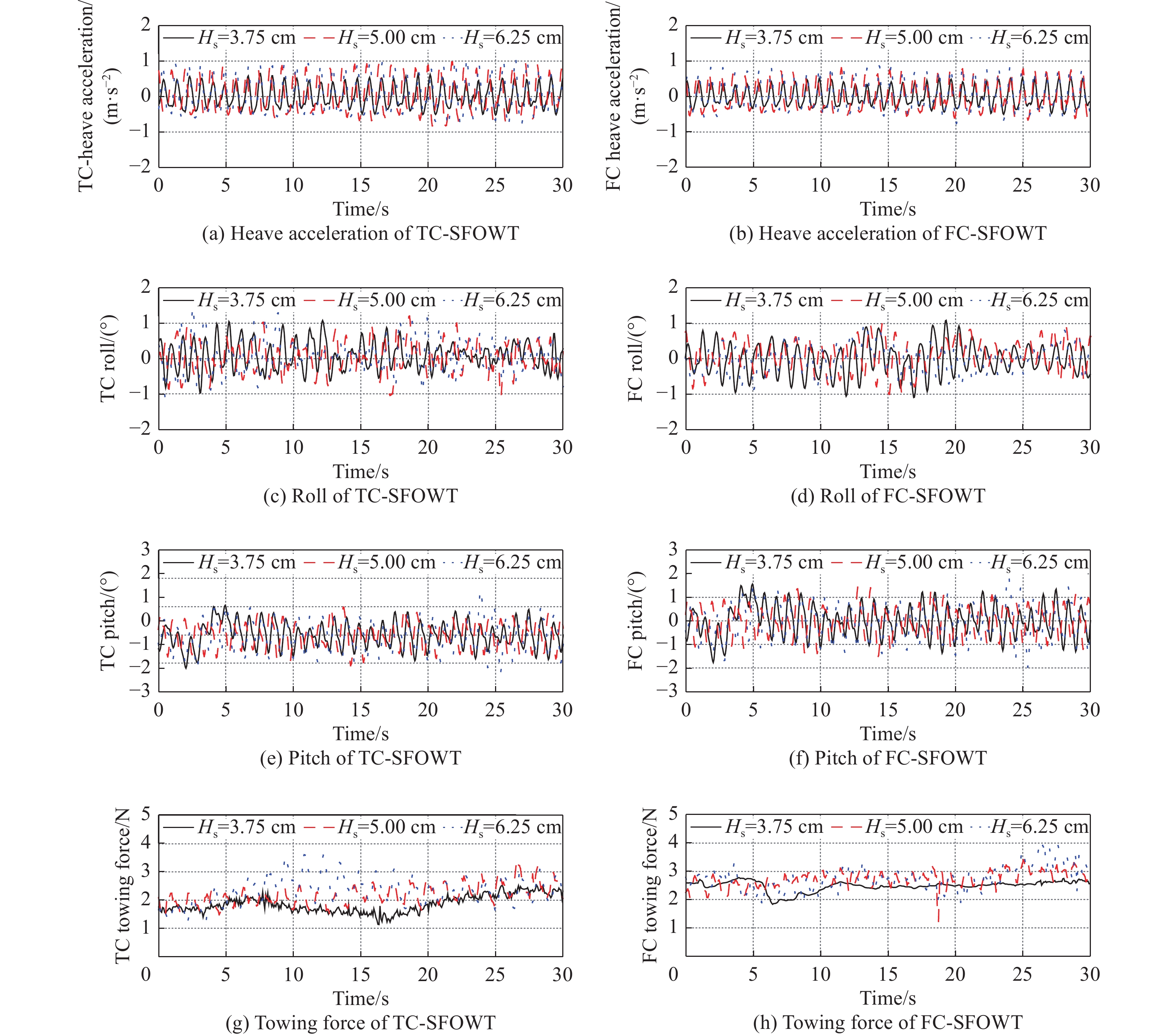
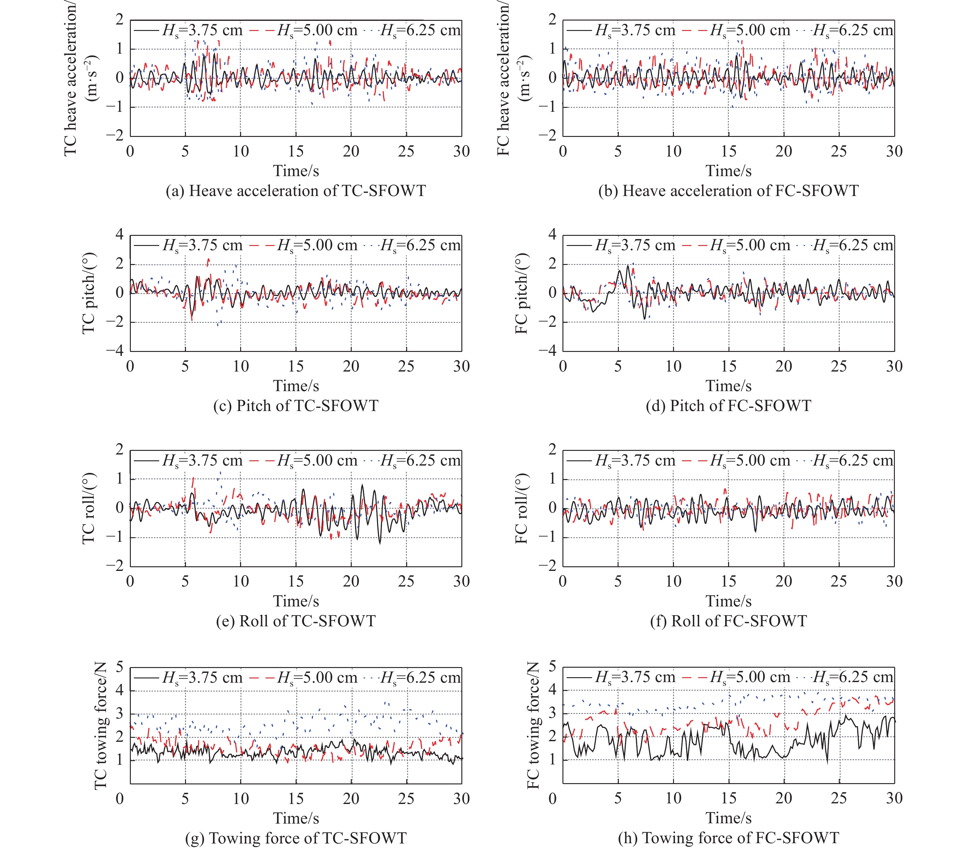
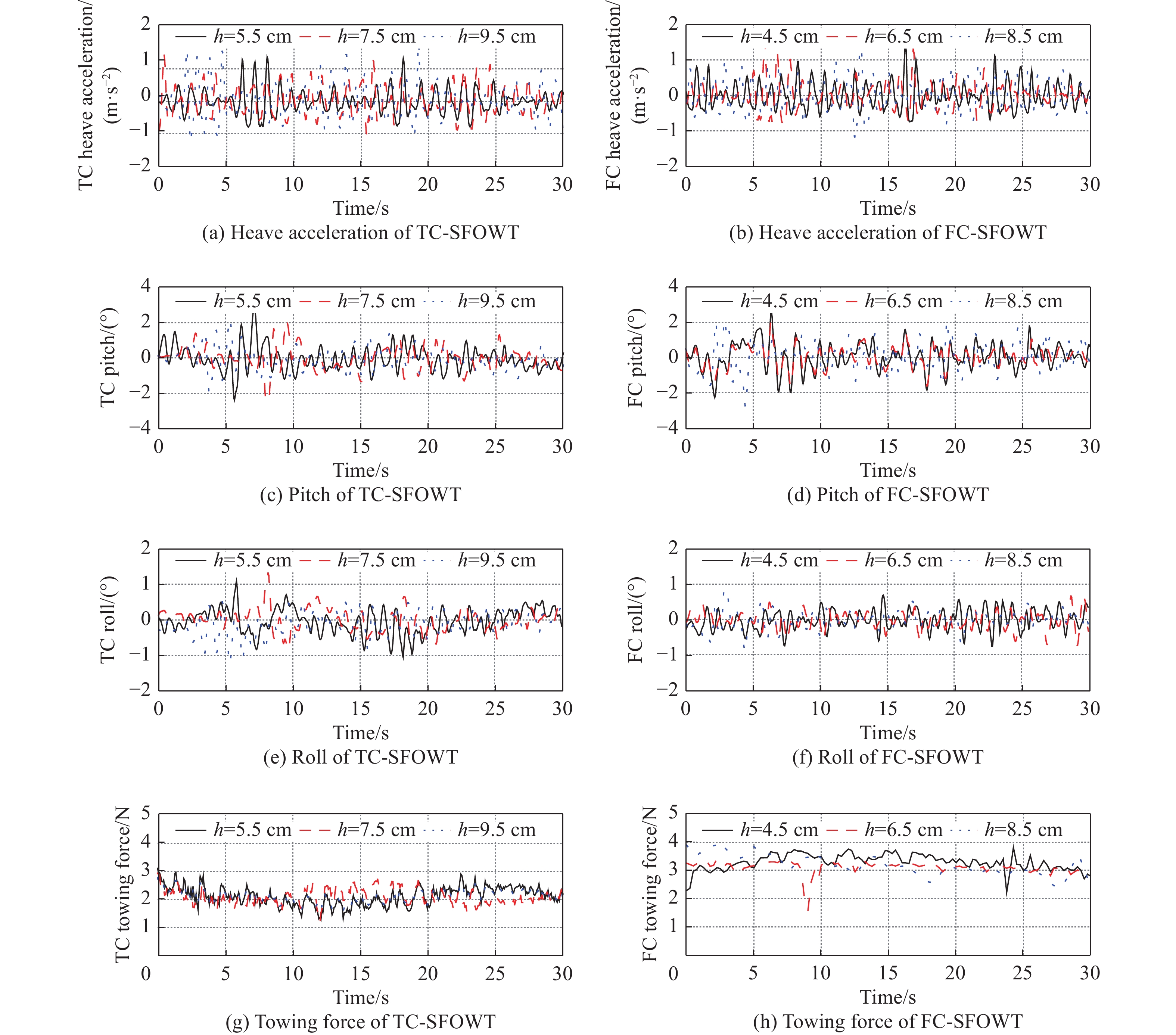
Fig. 7 is the time-history curves of heave acceleration, pitch, roll, and towing force of SFOWT under different significant wave heights during the towing process, and takes any 30 s during the towage process for analysis. With the increase of wave height, the response of SFOWT on each degree of freedom and the towing force is increasing, the heave acceleration response value of SFOWT under different working conditions fluctuates between ±2 m/s2, the pitch response value fluctuates between ±4°, the roll response value fluctuates between ±4°, both the heave acceleration and inclination angle meet the requirements of the towing specification.
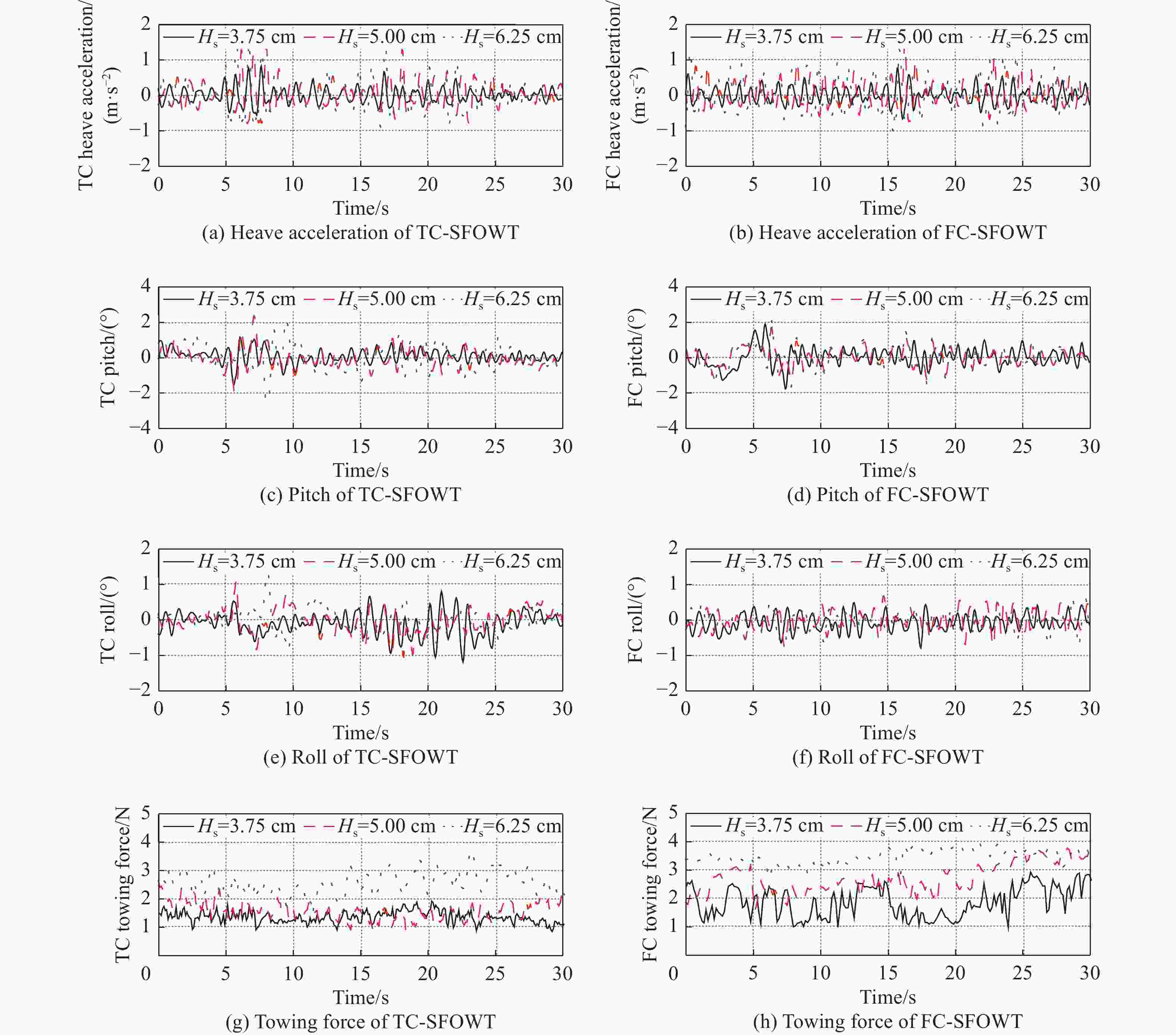
Figure 7. Response time-history curves of SFOWT towing motion at different significant wave heights (Tp=1.0 s)
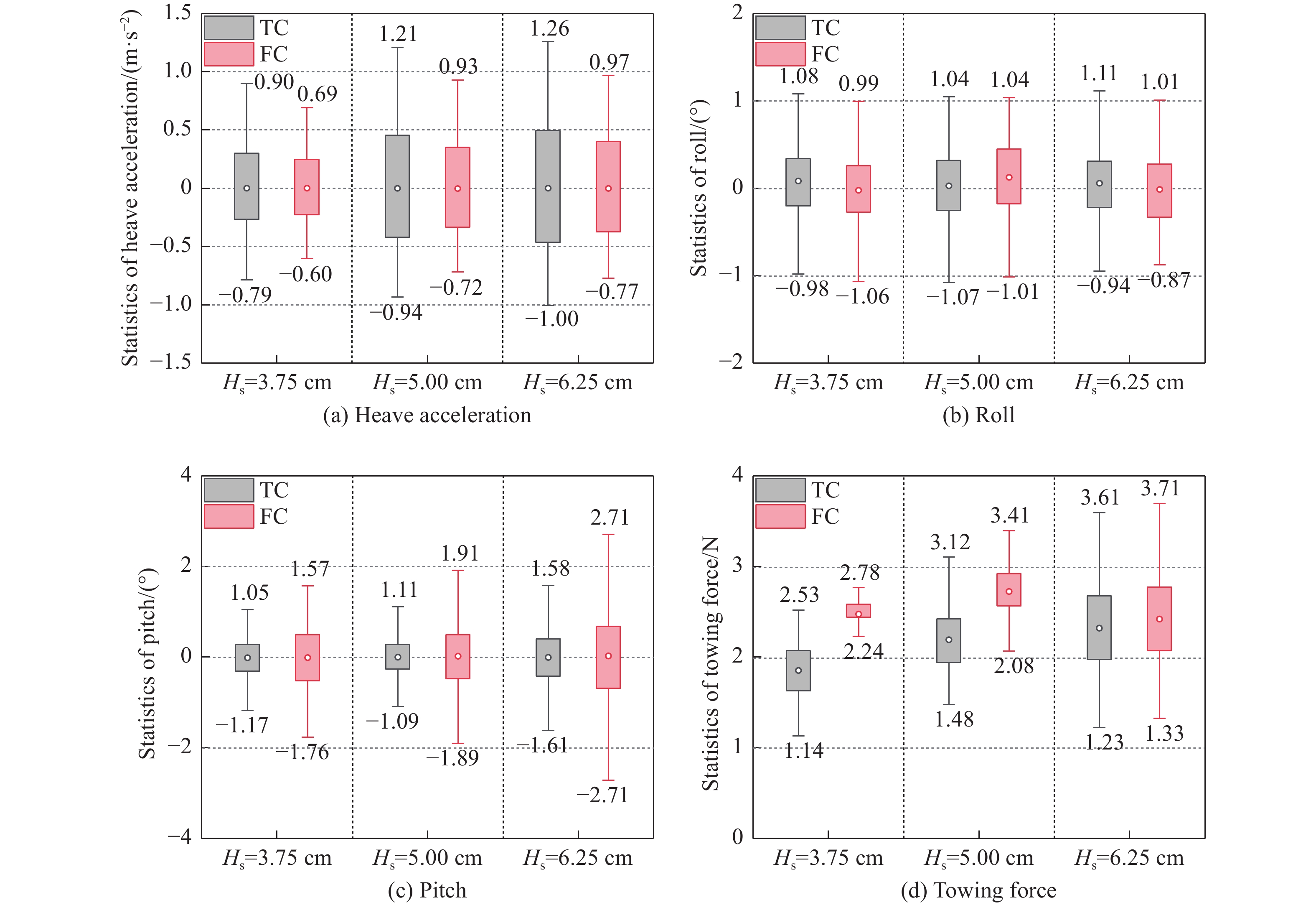
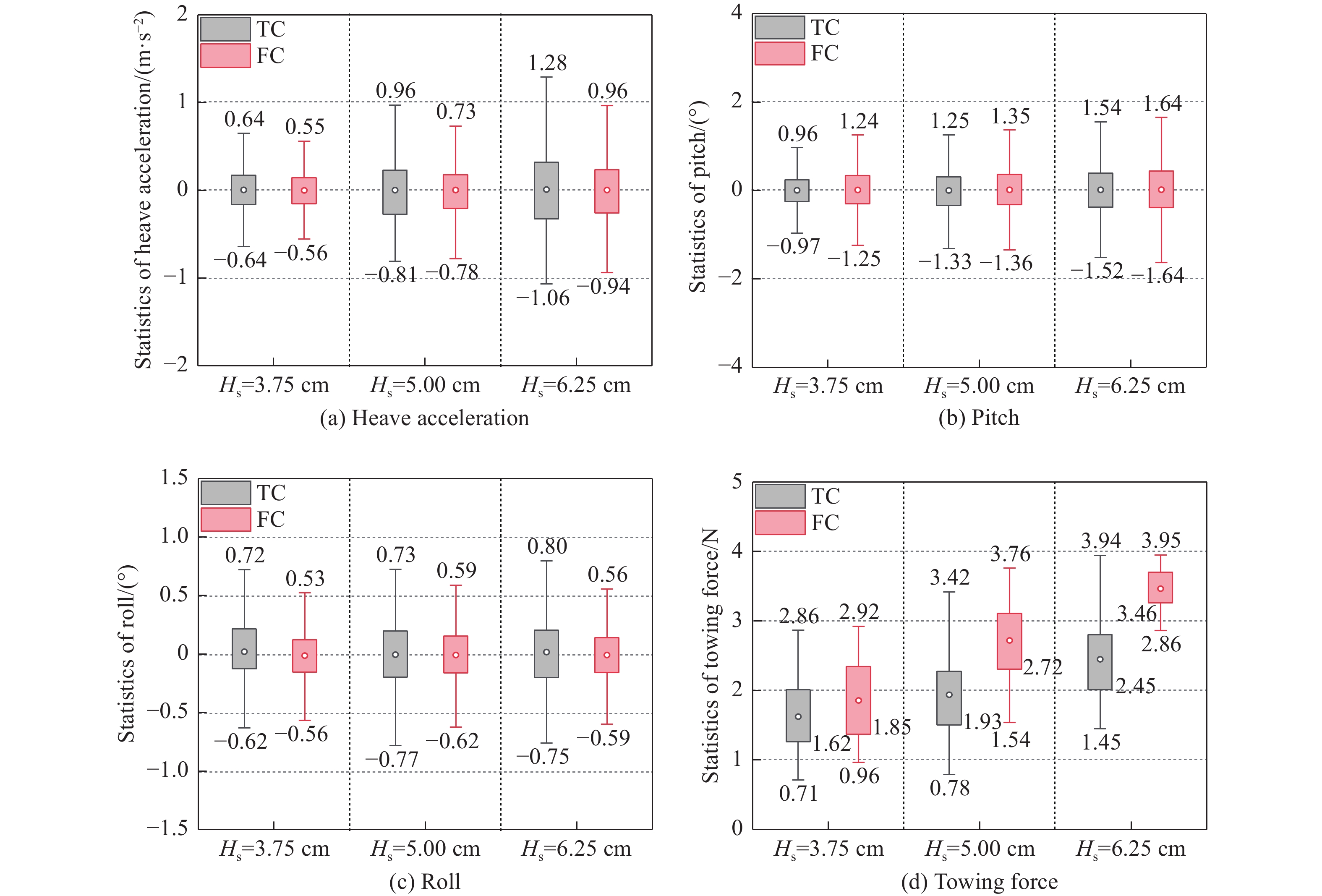
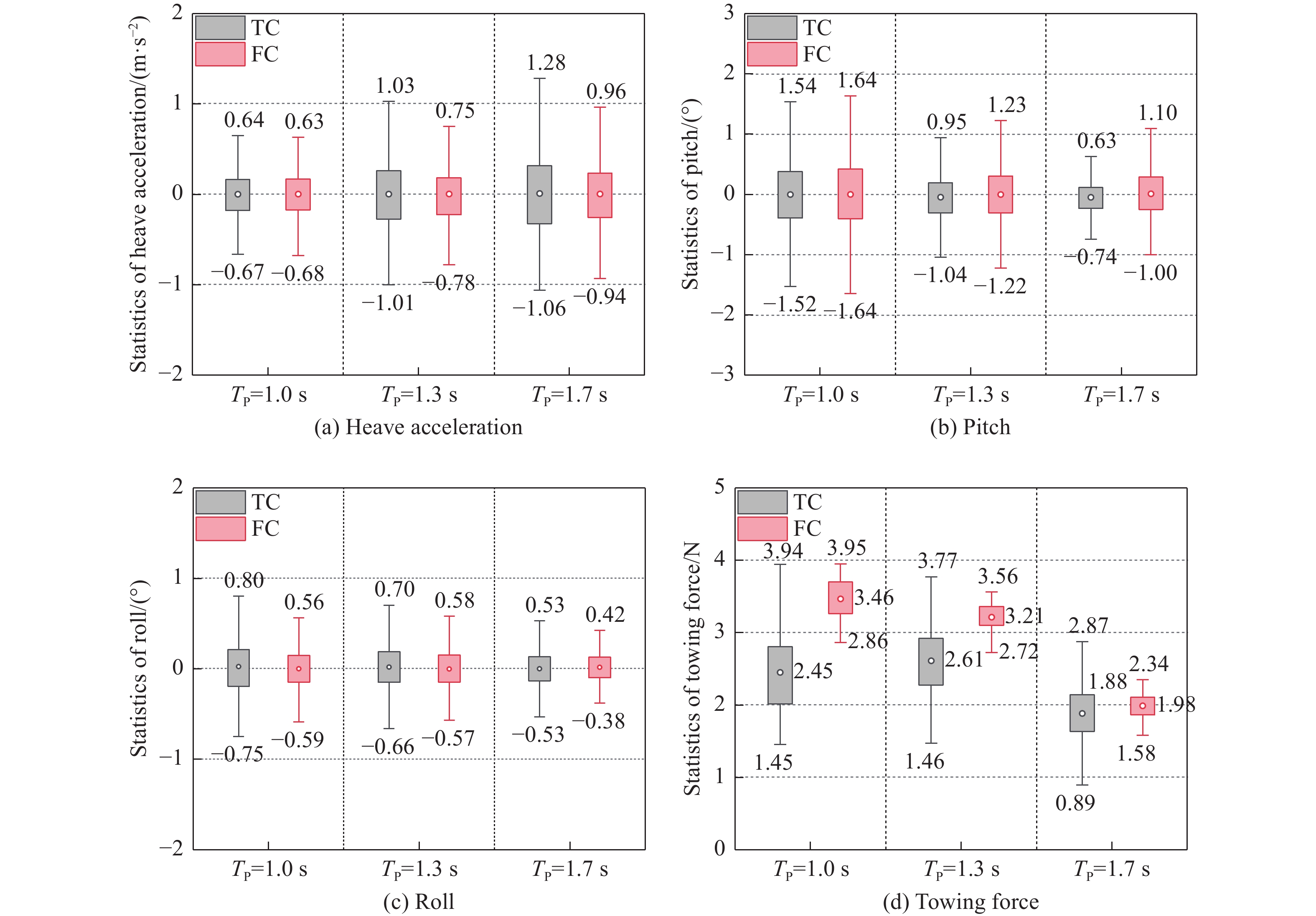
Fig. 8 shows the statistical characteristics of heave acceleration, pitch, roll, and tow cable force of SFOWT under different significant wave heights during towing. It can be found that when the significant wave height is 6.25 cm, the heave acceleration amplitude of the TC-SFOWT is 1.28 m/s2, compared with working conditions 1 and 2, it increased by 100.0% and 50.0% respectively. The amplitude of the heaving acceleration of the FC-SFOWT is 0.96 m/s2, compared with working conditions 1 and 2, it increased by 74.6% and 41.8% respectively. It can be seen that the increase of the significant wave height has a greater influence on the motion in the heaving direction of the TC-SFOWT. To compare the responses of the respective degrees of SFOWT of the two structural types under the same working conditions, the TC-SFOWT has slightly larger heave acceleration, roll angle, slightly smaller pitch angle, and towline force than the FC-SFOWT. When the significant wave height is 6.25 cm, the average towing force of the two structural types of SFOWT is 2.45 N and 3.46 N respectively. Since the FC-SFOWT has a larger underwater area than TC-SFOWT, the viscosity of water is stronger, so a greater towing force is required.
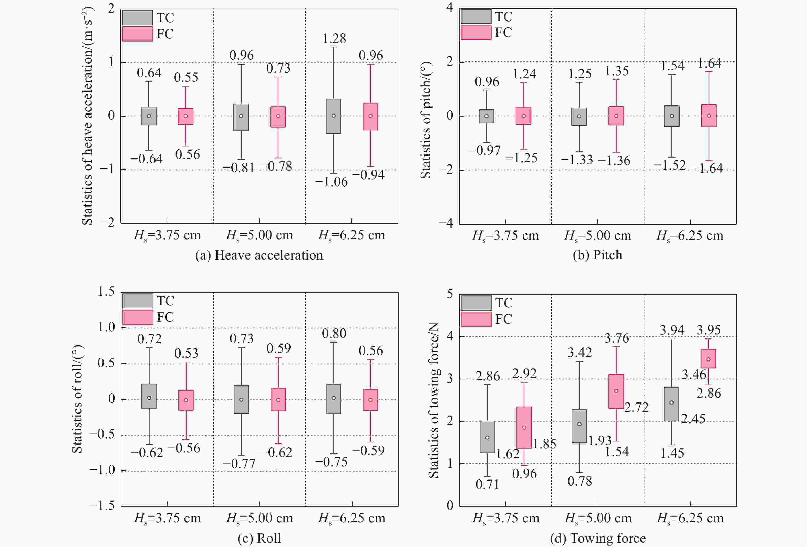
Figure 8. Motion response statistics of the SFOWTs under different significant wave heights (Tp=1.0 s)
-
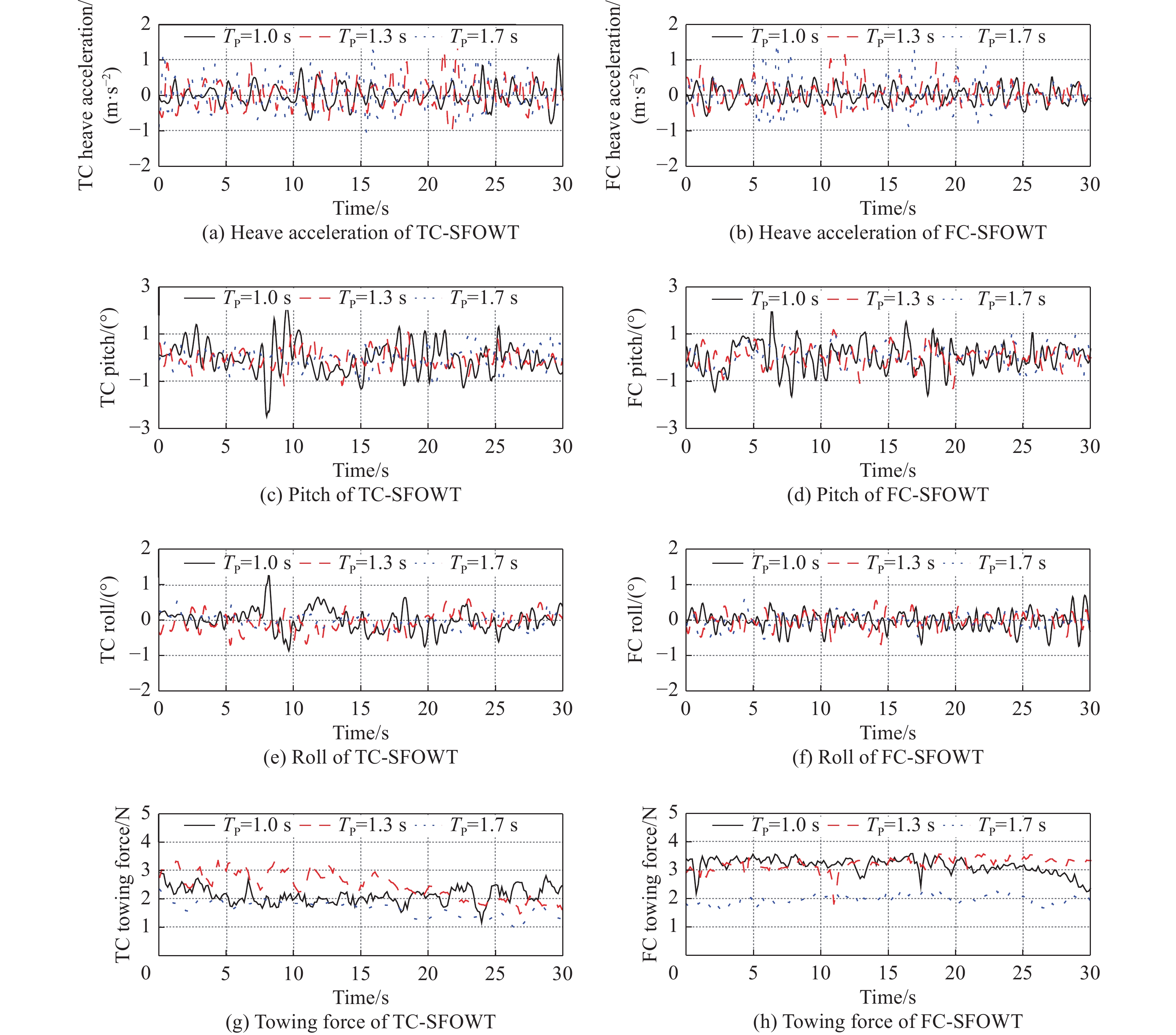
Fig. 9 and Fig. 10 respectively show the time-history curves and statistical values of heave acceleration, pitch, roll, and towline force of SFOWT, during towing under different spectral peak periods. When the wave period differs greatly from the inherent period of SFOWT itself, with the increase of the wave period, except for the heave acceleration, the response of each degree of freedom of SFOWT presents a decreasing trend. Compared with the FC-SFOWT, the TC-SFOWT also has larger heave acceleration, roll value, and smaller pitch value and towline force. When the peak period is 1.7 s, the natural period of the heave of TC-SFOWT is 1.6 s, and the natural period of heave of FC-SFOWT is 1.9 s. The wave period is close to the natural period of the test model heave, resulting in resonance, when the spectrum peak period is 1.6 s, the heave acceleration value of SFOWT is relatively large.
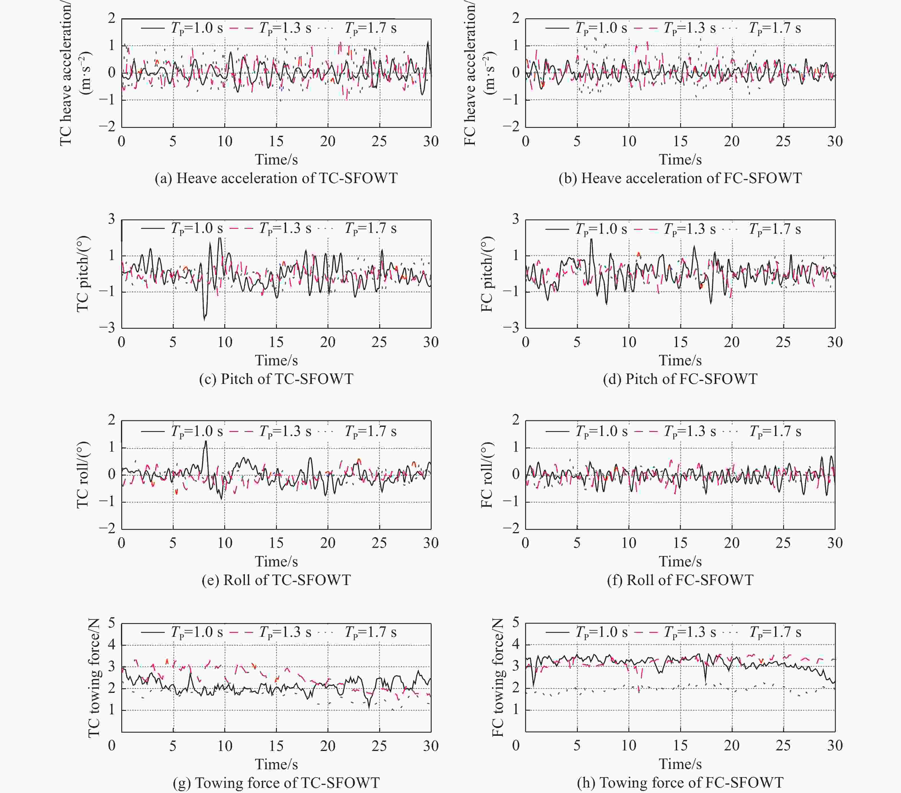
Figure 9. Response time-history curves of SFOWT towing motion at different peak periods (Hs=6.25 cm)
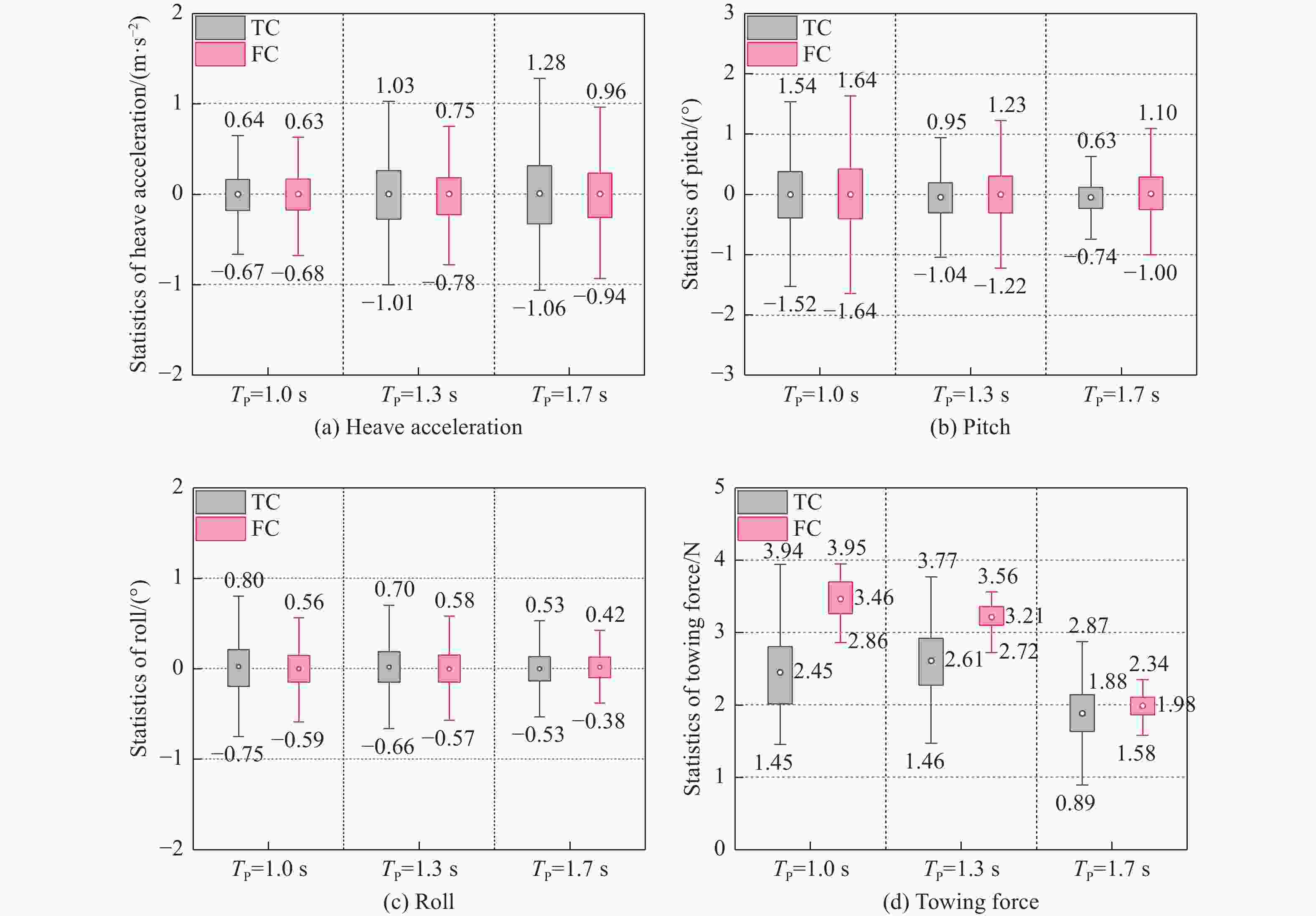
Figure 10. Motion response statistics of the SFOWTs under different peak periods (Hs=6.25 cm)
-
Explore the SFOWT in the process of towing the whole machine, the response of the streamer point height to the motion of each degree of freedom, and the effect of the height of the towline point on the magnitude of the towline force, to determine the best towing point location and lay the foundation for the analysis of subsequent working conditions. In this paper, h is used to replace the height of the towing point. The working conditions design is shown in Table 7.
Working conditions number 11 12 13 TC-SFOWT Model/cm 5.5 7.5(Free surface) 9.5 Prototype/m 4.4 6.0(Free surface) 7.6 FC-SFOWT Model/cm 4.5 6.5(Free surface) 8.5 Prototype/m 3.6 5.2(Free surface) 6.8 Table 7. Experimental conditions of the influence of towing point height on the towing process
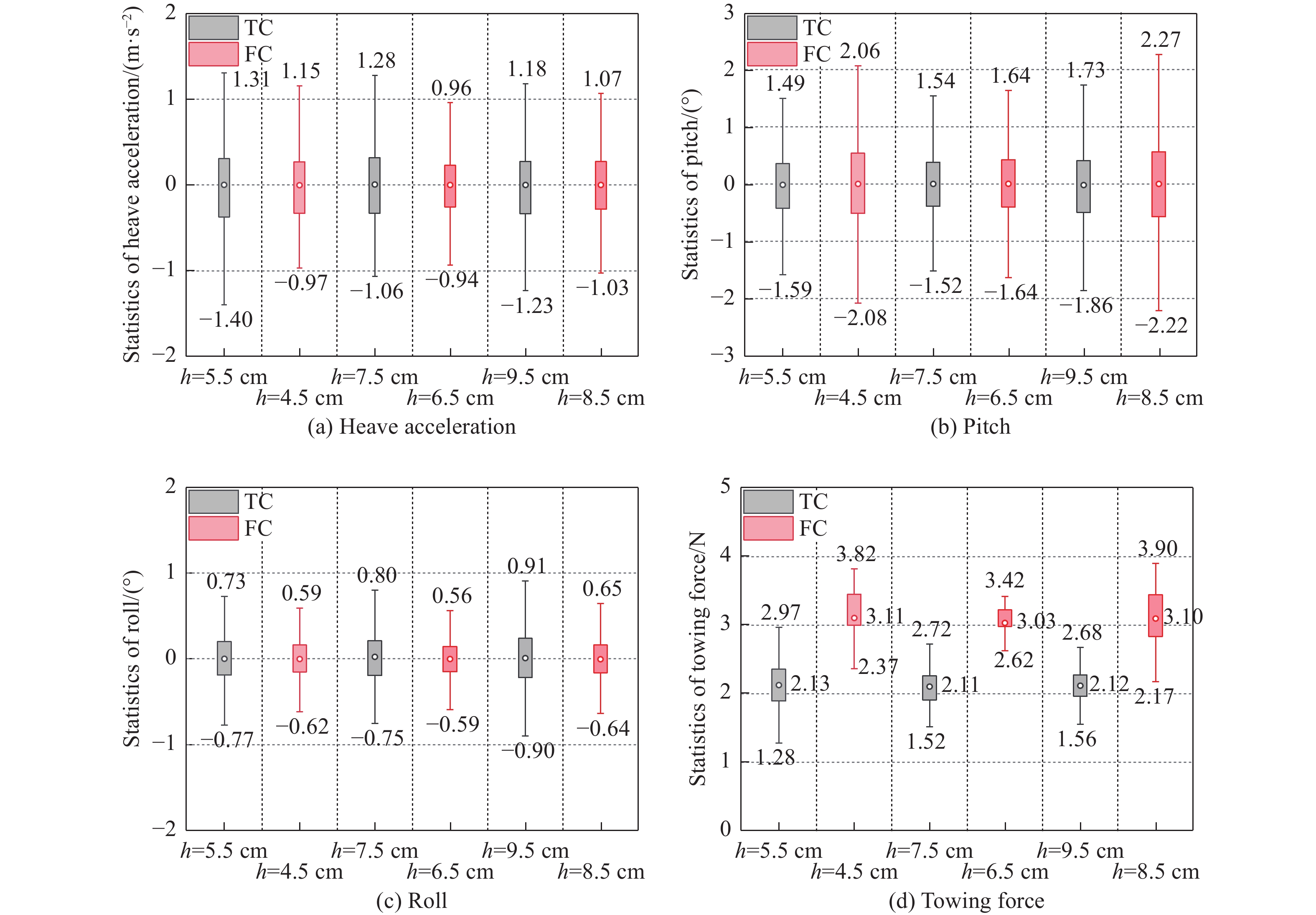
Fig. 11 and Fig. 12 respectively show the time-history curves and statistical values of the heave acceleration, pitch, roll, and towline force of the SFOWT during towage at different towline point heights. Analysis shows that the height of the towing point above and below the waterplane will increase the response of SFOWT in each degree of freedom, but has little effect on the average value of the towing force. Because the high tow point and low tow point will increase the overturning moment of SFOWT, it has a larger pitch value, but the effect on a roll is not great. When the towing point is below the waterplane, the pitch angle amplitudes of the two types of SFOWT are 1.59° and 2.08° respectively, compared with the conditions where the towing point is located at the waterplane, it increases by 3.1% and 26.8% respectively. When the towing point is above the water surface line, the pitch angle amplitudes of the two types of SFOWT are 1.86° and 2.27° respectively, compared with the conditions where the towing point is located at the waterplane, it increases by 20.8% and 38.4% respectively. When the height of the towing point is level with the waterplane, the towing force amplitudes of the two types are respectively 11.1% and 14.7% lower than those of the other two working conditions. Therefore, in actual engineering, the height of the towing point should be arranged where the waterplane of the structure is self-floating, to reduce motion response during towing.
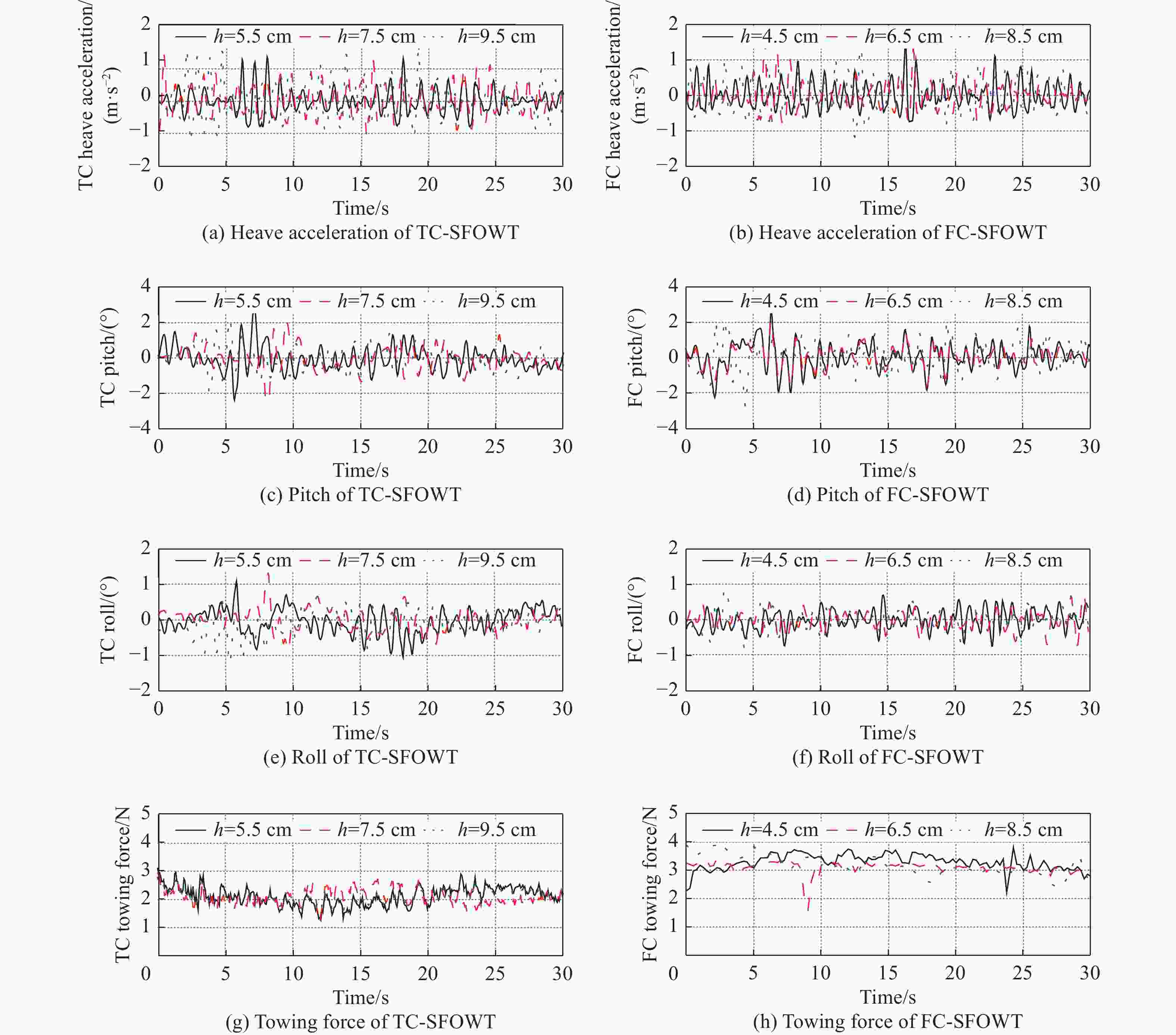
Figure 11. Response time-history curves of SFOWT towing motion at different towing point heights (Hs=6.25 cm, Tp=1.0 s)
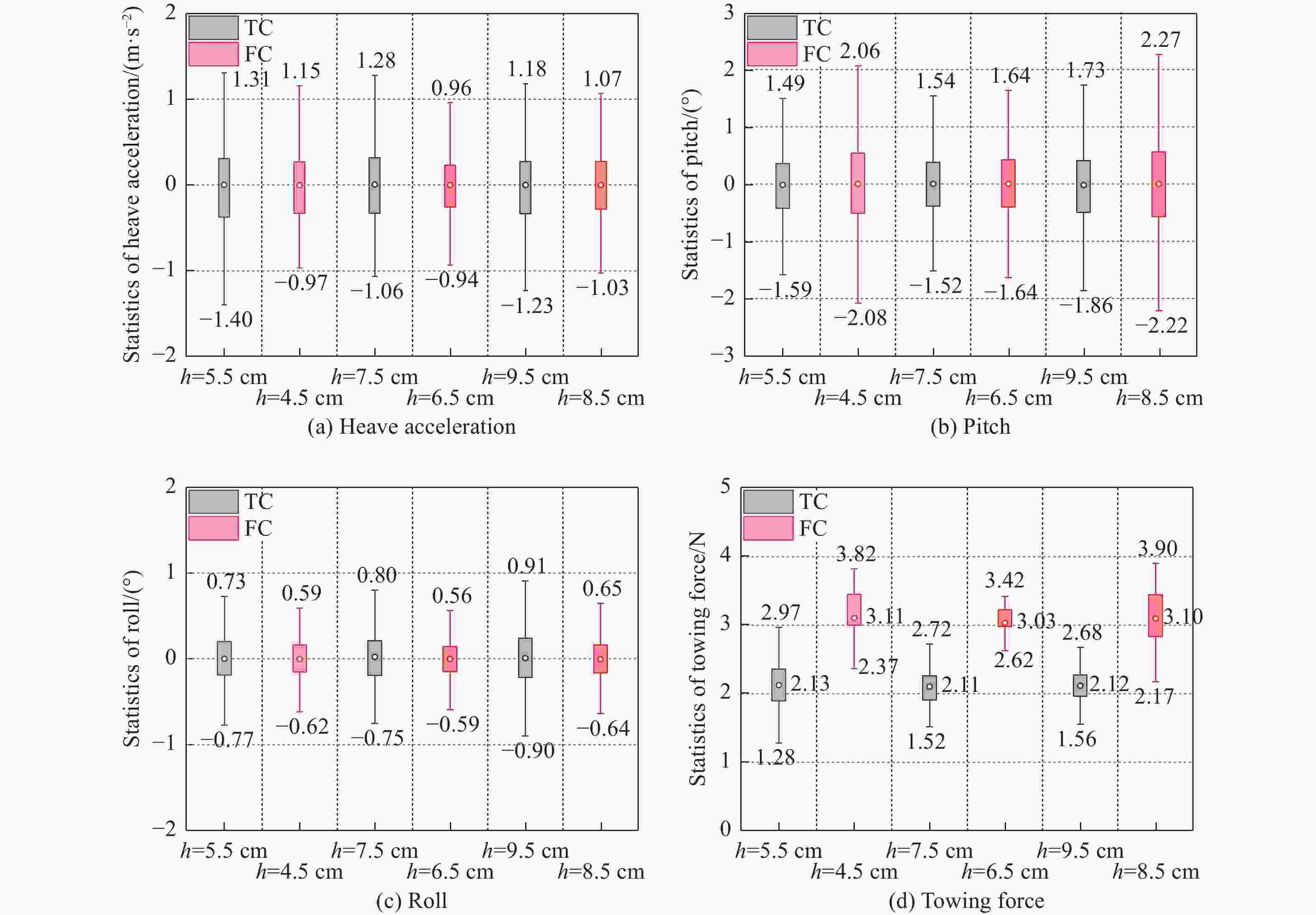
Figure 12. Motion response statistics of the SFOWTs under different towing point heights (Hs=6.25 cm, Tp=1.0 s)
-
Based on the towage process of the foundation structure of the TC-SFOWT and FC-SFOWT, a physical model test was carried out in an irregular wave environment. The motion response of the two types of floating wind turbines in each degree of freedom and the force of the towing cable is compared and analyzed during the towing process.
The free attenuation test in still water shows that the natural periods of heave, pitch, and roll of the TC-SFOWT prototype are 14 s, 42 s, and 42 s, respectively, the natural periods of heave, pitch, and roll of the FC-SFOWT prototype are 18 s, 39 s, and 39 s.
Under different working conditions, the heave acceleration amplitude of SFOWT all meets the requirement of less than 0.2 g in the towage specification, the roll and pitch amplitudes meet the requirement of ±5°, and the FC-SFOWT has better towing motion performance than the TC-SFOWT.
When the wave period is close to the natural period of the structure itself, the structure will resonate at the corresponding degrees of freedom, when the spectrum peak period is 1.7 s, SFOWT has a larger heave acceleration.
When the towing point is at the position of the water plane when the structure is self-floating, the response amplitude of the whole structure towing motion of SFOWT is small. Therefore, in the actual towing process, the towing point should be set flush with the water plane.
Comparision of Integrated Towing Motion Performance for Multi-Column Semisubmersible Floating Offshore Wind Turbines
doi: 10.16516/j.ceec.2024.2.02
- Received Date: 2023-05-21
- Rev Recd Date: 2023-06-06
- Available Online: 2023-09-26
- Publish Date: 2024-03-26
-
Key words:
- DTU 10 MW /
- submerged floating offshore wind turbine /
- integrated towing /
- motion response /
- free attenuation /
- model test
Abstract:
| Citation: | QI Xiling, LE Conghuan, REN Jianyu, et al. Comparision of integrated towing motion performance for multi-column semisubmersible floating offshore wind turbines [J]. Southern energy construction, 2024, 11(2): 17-30. DOI: 10.16516/j.ceec.2024.2.02 doi: 10.16516/j.ceec.2024.2.02

|

 DownLoad: