

 下载:
下载:
-
Many climate change-related extreme weather events are occurring with increasing frequency and intensity, causing catastrophic outages that serve as a powerful reminder of the vulnerability of current power systems[1]. Power system restoration has been well identified as one of the critical strategies to enhance system resilience. Generally, the objective of system restoration is to re-supply load as quickly as possible after an outage. To this end, for large-scale power systems, the generating units have to be restarted first; and then, the delivery systems should be energized to pool and transfer electric power to the demand side; the final stage picks up loads sequentially[2]. As the most critical operating strategy, restoration strategies meet all operating constraints by fully using the available resources. As one of the most widely used emerging transmission technologies, HVDC's contribution for system restoration should be carefully identified.
Few study addresses the HVDC restoration strategy at present, although the importance has been well identified. To fulfill this critical gap, the black-start capability of various HVDC system needed to be identified; and then the operating strategies should be designed. At present, there are two types of HVDC with different power electronic devices, i.e., LCC-HVDC and VSC-HVDC.
Traditionally, LCC-HVDC can't act as a restoration source in a blackout condition when serious faults occur in one side of the AC systems[3]. The classical line-commutated current-source converter (LCC-HVDC) based on the thyristor technology, which has been used for some decades and proven to be superior to the AC transmission in terms of operating cost and reliability[3-4]. Since LCC-HVDC requires commutation current supplied by strong AC systems and the receiving end system should be an active system. However, the latest development demonstrates that LCC-HVDC may be extended with restoration capability by sophisticated control strategies[5-6].
With the development of power electronics technology, novel HVDC technology is available. By using the insulate gate bipolar transistor (IGBT) components, Voltage Source Converter (VSC) technology are proposed. For VSC-HVDC projects, up until now, DC voltage has reached ±320kV and the transmission power reaches about 1000MW. VSC transmission system provides favorable control ability[7-8]. By PWM technology, the desired output voltage amplitude is controlled by modulating the width of constant DC voltage pulses. VSC-HVDC can be restarted without external support. As a result, VSC-HVDC is suggested as a tie line to provide energy for system restoration[9]. When the VSC-HVDC link is charged, the DC voltage across the capacitor rises. VSC can convert the DC voltage into the desired AC voltage by switching on or off converter bridges according to the pre-determined switching mode. By use of PWM, VSC will produce the AC voltage, which contains a fundamental component equal to the AC reference voltage in magnitude, frequency and phase.
HVDC connections doesn't not play a major role in wind power integration so far. The main reason is the traditional LCC-HVDC does not have black-start capability without auxiliary device. Due to the characteristics of VSC-HVDC, it can be used for wind farm restoration. Since wind farms usually behaves as a load during startup, this technology may be critical for the future power systems. A voltage waveform with appropriate amplitude and frequency has to be established to integrate the generators. Recently, it is reported that VSC-HVDC has full black-start capability for wind farms[10].
This paper comprehensively discusses the potential contributions for restoration of HVDC systems, including LCC-HVDC and VSC-HVDC. The wind farm restoration with VSC-HVDC will be studied as well.
-
The low losses and high power level enable LCC-HVDC to serve as the most economical connection for bulk power transmission over long distance at present. The application of HVDC at 800 kV has been found efficient, environmentally friendly and economically attractive for point to point power transmissions with 6 400 MW and more than 1 000 km.
The fast regulation and multiple control modes could be implemented by controlling the trigger phase of the converter. This control strategies provide high flexible for LCC-HVDC operation[11]. The major control modes employed by HVDC are as follows.
1) DC current control mode: maintaining the DC current constant.
2) DC voltage control mode: keeping either the sending terminal voltage or the receiving terminal voltage in a given range or a constant.
3) Firing angle control in the rectifier mode: keep the firing angle small during normal operation to reduce the reactive power consumption as well as holding certain regulation margin.
4) Extinction angle control in the inverter mode: maintain extinction angle above the given turn-off margin angle so as to lower the commutation failure risk.
-
For a long time, it was well known that the LCC-HVDC cannot supply a dead load. As a result, it cannot be used for restoration. However, the recent development of Siemens showed that the LCC-HVDC might be able to supply a dead load with a novel control strategy by implemented some control strategies[5]. In these method, when the inverter connected to a passive load, the firing pulses for inverters are synchronized to an independent sinusoidal signal, such as 60 Hz or 50 Hz. This is the major difference between the conventional control strategies of HVDC. Besides, the equivalent circuit on the inverter side presents capacitive feature at fundamental frequency to guarantee the normal commutation of the converter. The AC voltage at the inverter maintains constant with variable loads by means of controlling the DC currents of the converter.
The black-start sequence of LCC-HVDC is (1) the inverter filters are connected first, and (2) the inverter and the rectifier are deblocked in sequence.
During this process, the AC voltage of the inverter is raised slowly. The DC current must be large enough to enable the inverter to absorb all the reactive power generated by the filters. The DC voltage is kept at a low level to ensure the rectifiers and inverters operate at the firing angles close to 90°. As a consequence, the converter shall be designed in a range of 90° operation.
-
During restoration processes, the AC voltage reference could be achieved according to the pre-determined magnitude, phase angle and frequency. The HVDC link disconnects the de-energized grid from the operating grid and starts up the de-energized grid step-by-step after a blackout. Besides, VSC-HVDC can not only energize transmission lines at a lower voltage level and avoid severe over-voltage, but also allow remote end connection of transformers/reactors at a safe voltage level.
If the VSC-HVDC is connected with the passive network, the converter connected to the active network will charge the local and remote capacitors. When the DC voltage is promoted to the setting value, the converter will begin to start the primary devices such as the transformer and long distance line. Therefore, the voltage imposed on the transformer and the transmission line is established gradually. By this means, the inrush current during the energization of the transformers and the over-voltage during the closure of the long overhead transmission lines can be reduced.
At present, two VSC-HVDC projects, the Estlink HVDC Light in Norway and Eagle Pass project in the U.S.A., applied the VSC-HVDC as the black-start power source in the case of a weak AC system cut-off. black-start is implemented in Estlink for the Estonian side and this feature enables it to start parts of the Estonian network within minutes after a total blackout. During restoration, Estlink provides auxiliary power to selected power units. After restarting such a unit and connecting it to the network island, more generation can be connected. Estlink and the connected generation will share the load through the droop characteristic. When sufficient generation is connected to the network, the mode of operation of the converter can be changed from frequency/voltage control to power/voltage control.
There are three control modes for VSC-HVDC systems:
1) Constant DC voltage control: maintaining the DC side voltage of VSC is achieved by controlling charges in the large capacitors located on each side of the voltage source converters. At one of the converters, power flow import or export from a converter can be regulated to keep DC voltage constant on each capacitor. A simple PI controller can control the power flow by adjusting the phase angle.
2) Constant AC current or active power: if the phase angle is used to control DC voltage by controlling power import or export from the receiving end inverter, the other available signal at the sending end VSC can be applied to control the total power flow.
3) Constant AC voltage or reactive power control: reactive power control can keep a fixed reactive power exchange independently with the active power exchange. For constant AC voltage control, the converter supplies reactive power up to its limits to keep the grid voltage stable during disturbances and load changes. A simple PI controller can be used to regulate AC side voltage, reactive power import or export from VSC. The output of the PI controller adjusts the modulation index to meet its control objective.
-
VSC-HVDC systems provide more alternative methods for system restoration[11]. Compared with traditional system restoration, the benefits of VSC-HVDC systems can be summarized in follows:
1) Since VSC has black-start capability, it has been proved to be initial energy resource for system restoration. In the traditional power system restoration, only black-start units can be employed for this duty.
2) AC voltage in a VSC-HVDC system is controllable.It can provide a flexible resource for voltage and reactive power regulation during system restoration. In the traditional power system restoration, only the excitation system of generating units can implement this task.
3) VSC-HVDC system can control system frequency directly. This characteristic might benefit system restoration during load pick-up.
4) Due to the controllability during energizing VSC-HVDC, the over-voltage problem resulting from electromagnetic transients can be avoided during system restoration process.
-
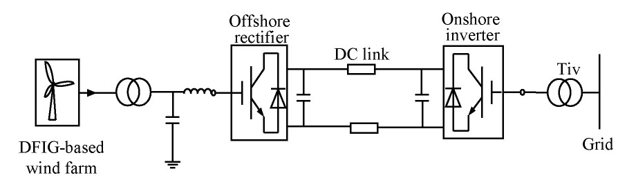
Usually, LCC-HVDC is used for offshore wind power integration at the locations without strong AC systems. In those systems, the corresponding auxiliary service is needed to enable the operation of the LCC-HVDC even during periods with little wind. Possible solutions may be the installation of a STATCOM or a diesel-driven generator to ensure black-start capability. For the system illustrated in Figure 1, the STATCOM is equipped to provide the commutation voltage for converter and fast reactive power support. These additional components made LCC-HVDC possible for wind farm integration.

图 Fig.1 LCC-HVDC for Wind Farm Integration and Black-start
After a partial or complete outage occurs in a system with DFIG-based wind farm and the HVDC system, this system can be restored with the aid of the STATCOM. Usually, STATCOM should be equipped about 30%~40% of the system capacity. For offshore wind farms, due to the difficulties of maintenance, self-recovery capability is more important.
-
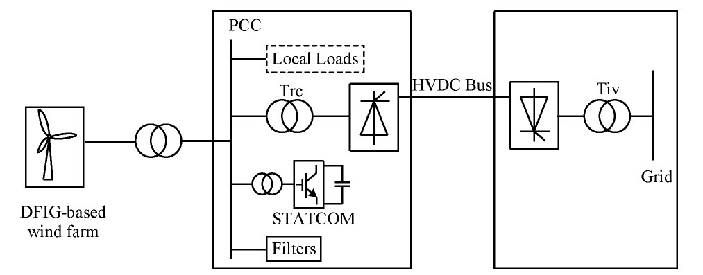
The topology of a VSC-HVDC for offshore wind farm integration is shown in Figure 2.

图 Fig.2 VSC-HVDC for Wind Power Integration
The VSC-HVDC connects the offshore DFIG-based wind farm to an AC grid. The link includes two converters (the offshore converter and onshore converter), each converter includes a VSC, two AC cables, an interface transformer, DC capacitors and AC filters.
With VSC-HVDC, the system can be restarted even in the case of weak onshore AC grid connection. Since the current flowing IGBT can be switched off and an active commutation voltage is unnecessary. Furthermore, the active and reactive power supply can be controlled independently.
There is no difference for a wind turbine being connected to a strong AC system or to a VSC-HVDC converter station. The VSC-HVDC offshore converter behaves as a slack bus in the offshore grid, absorbing the produced active power of the wind turbines, hereby controlling the offshore frequency and delivering the required reactive power to control the AC voltage.
-
To verify the black-start capability of LCC-HVDC with STATCOM, an HVDC system is modeled using twelve-pulse converters according to the CIGRE benchmark model in PSCAD/EMTDC[12]. The wind farm is represented by the lumped model of the single DFIG with rated power 1 000 MVA, connected to the PCC through the 33 kV/132 kV transformer. The DC link voltage of the STATCOM is 35 kV and the capacitor is 20 000 μF. The 10kV/132 kV step up transformer is adopted to connect the STATCOM to PCC. In the model, the voltage base value is 500 kV and the power base value is 1 000 MW.
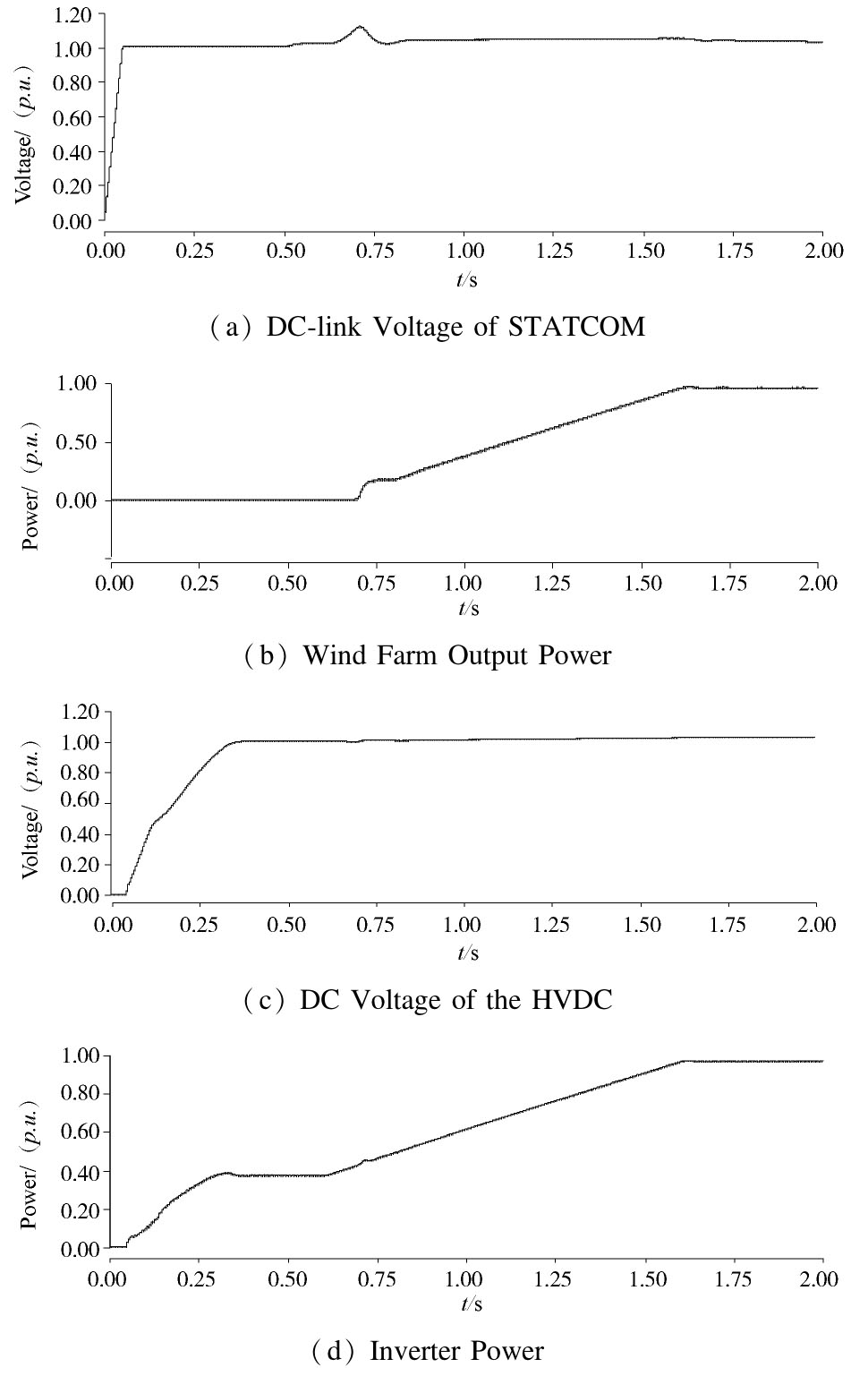
Fig. 3 (a)~(d) show the system responses during the black-start of the HVDC system with wind farm. At the first stage, i.e., 0~0.1 s, the DC link voltage of the STATCOM will be supplied by the standby generator and rises to the rated value. The STATCOM is put into operation and the AC voltage at PCC will be established. At 0.3 s, the inverter will be deblocked and the HVDC system DC voltage could be brought up. The excitation for the DFIG could be realized under the stable AC voltage and the wind farm outputs the active power gradually from 0.6 s. The rectifier is deblocked to transfer the active power from the wind farm. At the same time, the auxiliary generator will be cut out. Due to the relatively slow controller, STATCOM has to absorb the temporary excess power produced by wind farm, resulting in the DC link voltage fluctuation. The HVDC system DC current climbs up and DC voltage reaches the rated value. The DC power is sent to the inverter as schedule and the black-start process is completed.

图 Fig. 3 System Responses During the black-start of the HVDC System with Wind Farm
-
Simulation studies of the black-start of VSC-HVDC integrating a wind farm are carried out. The rated capacity of the wind farm is 200 MW, connecting to the IGBT based VSC-HVDC through 100 km cable. The DC transmission voltage is ±150 kV.
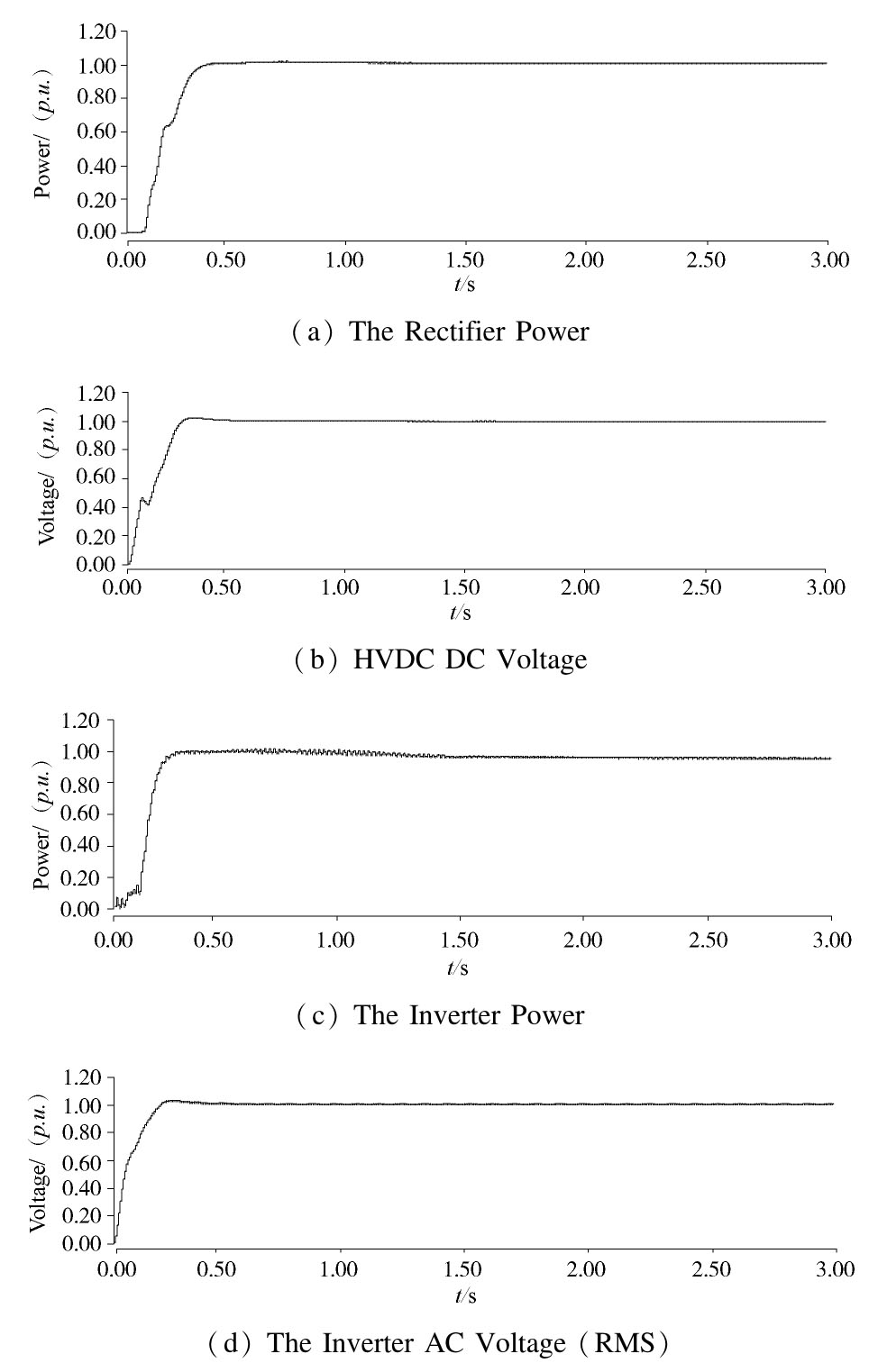
Fig. 4 (a)~(d) show the dynamic response of VSC-HVDC during the start-up period. At 0.15 s, the inverter is firstly deblocked. Then the power grid of the receiving end will charge the DC network through the converter, boosting the DC voltage to the rated value at 0.3 s as shown in Figure 4 (b). Meanwhile, by deblocking the rectifier, the AC voltage at PCC will be enhanced gradually and is well controlled. The DFIG based wind farm will connect to the grid. With the aid of the controller, the active power from the wind farm is totally absorbed by the rectifier and is fed into the receiving end grid. During the start-up, the DC power is injected slowly so as to reduce the transient oscillation in the HVDC and avoid the over-voltage.

图 Fig. 4 Dynamic Response of VSC-HVDC During the Start-up Period
-
Many HVDC projects have been in operation worldwide. It is critical to study the role of HVDC for system restoration. Traditionally, LCC-HVDC does not have the black-start capability. Recent researches found that its black-start capability can be implemented with appropriate control strategies applied and auxiliary devices. This capability contributes to wide utilization of LCC-HVDC with the renewable energy for the blackstart. Moreover, the latest development of power electronic components enhances the application of VSC-HVDC, which has the critical black-start capability and is a preferable choice in system restoration.
基于HVDC技术的系统黑启动方法
DOI: 10.16516/j.gedi.issn2095-8676.2016.02.009
CSTR: 32391.14.j.gedi.issn2095-8676.2016.02.009
-
摘要:
当今电力系统中高压直流技术已得到了广泛的应用。高压直流系统具有与交流输电系统不同的功能和特性,目前电力系统呈现出交直流混联的特点。文章研究了基于高压直流技术特征的黑启动策略,首先简单回顾了不同高压直流系统的结构及控制策略,并基于两种目前最广泛应用的高压直流技术,即电流源型高压直流以及电压源型高压直流技术,对高压直流系统的黑启动能力及顺序进行了研究。另外,对采用结合STATCOM的LCC-HVDC以及VSC-HVDC技术联网的风电场,文章通过PSCAD/EMTDC对其黑启动过程进行了仿真并比较验证了两种技术的动态性能。 Abstract:HVDC is widely used in power systems today. Different from AC transmission systems, HVDC systems have their special capabilities and characteristics. As more HVDC systems are integrated into power systems, startup strategies based on HVDC systems have to be carefully evaluated. In this paper, two kinds of most widely used HVDC technologies, i. e., LCC-HVDC and VSC-HVDC, are introduced. After a brief introduction of structures and control strategies of different HVaDC systems, the black-start capability and black-start sequence are discussed. Moreover, the black-start process of wind farms using LCC-HVDC with STATCOM, as well as VSC-HVDC, is simulated with PSCAD/EMTDC to demonstrate the dynamic performances of the two technologies. -
Key words:
- LCC-HVDC /
- VSC-HVDC /
- blackstart /
- wind farm /
- STATCOM
-
[1] North American Electric Reliability Corporation (NERC). Severe Impact Resilience: Considerations and Recommendations [R]. 2012. [2] HOU Y, LIU C C, SUN K, et al. Computation of Milestones for Decision Support During System Restoration[J]. IEEE Transactions on Power Systems, 2011(26): 1399-1409. [3] KURUGANTY S. Comparison of Reliability Performance of Group Connected and Conventional HVDC Transmission Systems[J]. IEEE Transactions on Power Delivery, 1995, 10(4): 1889-1895. [4] KUNDER P. Power System Stability and Control [M]. U.S.A.: New York, 1996. [5] LI G, ZHAO C, ZHANG X, et al. Research on “Soft Start-up” of VSC-HVDC in Power System Restoration After Blackouts [C]. Industrial Electronics and Applications, 2007. [6] GUO C, ZHAO C. A New Technology for HVDC Start-up and Operation Using VSC-HVDC System [C]. IEEE Power Energy Society General Meeting, 2009. [7] FLOURENTZOU N, AGELIDIS V G, DEMETRIADES G D. VSC-Based HVDC Power Transmission Systems: An Overview[J]. IEEE Transaction on Power Electronics.2009, 24(3): 25-30. [8] GUO C, ZHAO C. Supply of an Entirely Passive AC Network Through a Double-infeed HVDC System[J]. IEEE Transactions on Power Electronics.2010, 24(11): 2835-2841. [9] YING J, DUCHEN H, KARLSSON M, et al. HVDC with Voltage Source Converters - a Powerful Standby Black Start Facility[J]. IEEE Transmission and Distribution Conference and Exposition, 2008. [10] XU L, YAO L, SASSE C. Grid Integration of Large DFIG Based Wind Farms Using VSC Transmission[J]. IEEE Transaction on Power System.2007, 22(3): 976-984. [11] ANDERSEN B R, XU L. Hybrid HVDC System for Power Transmission to Island Networks[J]. IEEE Transaction on Power Delivery.2004, 19(4): 1884-1890. [12] LU Xiaojun, LIN Weixing, YAO Liangzhong, et al. Parameter Design and Control Strategy of Dynamic Braking Resistor for Aiding Fault Ride-through of Offshore Wind Farms Connected Through VSC-HVDC[J]. Sothern Power System Technology, 2015, 9(5): 19-26. -

图(4)
计量
- 文章访问数: 391
- HTML全文浏览量: 155
- PDF下载量: 31
- 被引次数: 0
