• Peer Review
  • Non-profit
  • Global Open Access
  • Green Channel for Rising Stars
Volume 10 Issue 3
May  2023
Turn off MathJax
Article Contents

ZHOU Hang, LI Shaohua, WANG Hui, XU Chunli, TANG Xiaoshu, ZHOU Jun. Modelling and Simulation of Photovoltaic Coupling Water Electrolysis Hydrogen Production System[J]. SOUTHERN ENERGY CONSTRUCTION, 2023, 10(3): 104-111. doi: 10.16516/j.gedi.issn2095-8676.2023.03.011
Citation: ZHOU Hang, LI Shaohua, WANG Hui, XU Chunli, TANG Xiaoshu, ZHOU Jun. Modelling and Simulation of Photovoltaic Coupling Water Electrolysis Hydrogen Production System[J]. SOUTHERN ENERGY CONSTRUCTION, 2023, 10(3): 104-111. doi: 10.16516/j.gedi.issn2095-8676.2023.03.011

Modelling and Simulation of Photovoltaic Coupling Water Electrolysis Hydrogen Production System

doi: 10.16516/j.gedi.issn2095-8676.2023.03.011
  • Received Date: 2022-12-08
  • Rev Recd Date: 2023-02-22
  • Available Online: 2023-04-04
  • Publish Date: 2023-05-10
  •   Introduction  This study proposes a photovoltaic coupling electrolysis water hydrogen production system modelling method with the purpose of solving the problem of inconsistency and mismatching of the simulation signals between electrolyser and others modules. The electrolyser is the key equipment in the photovoltaic-coupled water electrolysis hydrogen production system. The common simulation model of the electrolyser is mostly based on the electrochemical theory and established by using the signal model, which could cause signal transmission mismatching and increase system complexity.   Method  In order to solve the problems, it was proposing a method of simulating the electrical characteristics of the electrolytic cell by using the equivalent resistance. By fitting the working characteristic curve of the known electrolyser, the relationship between the working current and the impedance of the electrolyser was obtained. The information of the equivalent resistance of the electrolyser was inherited from the fitting curve and connected to the system as a load. When the system power supply fluctuated, the electrolyser simulation module could adjust the load according to the system working conditions, to achieve linkage with the system power supply.   Result  The simulation results show that the built photovoltaic-coupled water electrolysis hydrogen production system can accurately predict the hydrogen production according to the input light condition and enable load adjustment with the fluctuation of photovoltaic power supply, additionally have a residual value of the fitting result of ≤±0.2.   Conclusion  This method simplifies the photovoltaic coupling electrolysis water hydrogen production simulation system, unifies the simulation signal, and forms system blocks to facilitate system expansion. The simulation output results are in line with the actual operation of the electrolyser and have achieved the expected goal, which proves the feasibility of the simulation method.
  • [1] BRAUNS J, TUREK T. Alkaline water electrolysis powered by renewable energy: a review [J]. Processes, 2020, 8(2): 248. DOI:  10.3390/pr8020248.
    [2] ZHANG F, ZHAO P C, NIU M, et al. The survey of key technologies in hydrogen energy storage [J]. International journal of hydrogen energy, 2016, 41(33): 14535-14552. DOI:  10.1016/j.ijhydene.2016.05.293.
    [3] DAHBI S, MAZOZI I, EL OUARIACHI M, et al. Implementation of a multi-control architecture in a photovoltaic/grid/electrolysis system for usual use and clean storage by hydrogen production [J]. International journal of renewable energy research, 2017, 7(4): 1825-1835. DOI:  10.20508/ijrer.v7i4.6275.g7226.
    [4] MANDAL B, SIRKAR A, SHAU A, et al. Effects of geometry of electrodes and pulsating DC input on water splitting for production of hydrogen [J]. International journal of renewable energy research, 2012, 2(1): 99-102. DOI:  10.1097/00005344-199000153-00003.
    [5] BILGIN O. Evaluation of hydrogen energy production of mining waste waters and pools [C]//Proceedings of the International Conference on Renewable Energy Research and Applications, Palermo, Italy, November 22-25, 2015. Palermo: IEEE, 2015: 557-561.
    [6] KOIWA K, TAKAHASHI R, TAMURA J. A study of hydrogen production in stand-alone wind farm [C]//IEEE Power Electronics Society (PELS). Proceedings of the International Conference on Renewable Energy Research and Applications, Nagasaki, Japan, November 11-14, 2012. Nagasaki: IEEE, 2012: 1-6.
    [7] MARTINEZ D, ZAMORA R. MATLAB SIMSCAPE model of an alkaline electrolyser and its simulation with a directly coupled PV module [J]. International journal of renewable energy research, 2018, 8(1): 552-560.
    [8] GARCÍA-VALVERDE R, MIGUEL C, MARTÍNEZ-BÉJAR R, et al. Optimized photovoltaic generator-water electrolyser coupling through a controlled DC-DC converter [J]. International journal of hydrogen energy, 2008, 33(20): 5352-5362. DOI:  10.1016/j.ijhydene.2008.06.015.
    [9] DAHBI S, ABOUTNI R, AZIZ A, et al. Optimised hydrogen production by a photovoltaic-electrolysis system DC/DC converter and water flow controller [J]. International journal of hydrogen energy, 2016, 41(45): 20858-20866. DOI:  10.1016/j.ijhydene.2016.05.111.
    [10] 戴凡博. PEM电解水制氢催化剂及直接耦合光伏发电系统建模研究 [D]. 杭州: 浙江大学, 2020.

    DAI F B. Study of catalyst in PEM water electrolysis and directly coupling photovoltaic system simulation [D]. Hangzhou: Zhejiang University, 2020.
    [11] 周涣, 田易之. 光伏-PEM制氢直接耦合系统建模与仿真 [J]. 现代电子技术, 2022, 45(19): 178-181. DOI:  10.16652/j.issn.1004-373x.2022.19.032.

    ZHOU H, TIAN Y Z. Modeling and simulation of photovoltaic-PEM hydrogen production direct coupling system [J]. Modern electronics technique, 2022, 45(19): 178-181. DOI:  10.16652/j.issn.1004-373x.2022.19.032.
    [12] 江悦, 沈小军, 吕洪, 等. 碱性电解槽运行特性数字孪生模型构建及仿真 [J]. 电工技术学报, 2022, 37(11): 2897-2908. DOI:  10.19595/j.cnki.1000-6753.tces.210501.

    JIANG Y, SHEN X J, LÜ H, et al. Construction and simulation of operation digital twin model for alkaline water electrolyzer [J]. Transactions of China electrotechnical society, 2022, 37(11): 2897-2908. DOI:  10.19595/j.cnki.1000-6753.tces.210501.
    [13] 郭常青, 伊立其, 闫常峰, 等. 太阳能光伏-PEM水电解制氢直接耦合系统优化 [J]. 新能源进展, 2019, 7(3): 287-294. DOI:  10.3969/j.issn.2095-560X.2019.03.012.

    GUO C Q, YI L Q, YAN C F, et al. Optimization of photovoltaic-PEM electrolyzer direct coupling systems [J]. Advances in new and renewable energy, 2019, 7(3): 287-294. DOI:  10.3969/j.issn.2095-560X.2019.03.012.
    [14] 张财志. 太阳能电解水制氢系统的建模与仿真研究 [D]. 成都: 西南交通大学, 2009.

    ZHANG C Z. Modeling and simulation for solar-hydrogen system [D]. Chengdu: Southwest Jiaotong University, 2009.
    [15] 蔡国伟, 孔令国, 彭龙, 等. 基于氢储能的主动型光伏发电系统建模与控制 [J]. 太阳能学报, 2016, 37(10): 2451-2459. DOI:  10.3969/j.issn.0254-0096.2016.10.001.

    CAI G W, KONG L G, PENG L, et al. Modeling and control of active PV generation system based on hydrogrn storage [J]. Acta energiae solaris sinica, 2016, 37(10): 2451-2459. DOI:  10.3969/j.issn.0254-0096.2016.10.001.
    [16] 蔡国伟, 陈冲, 孔令国, 等. 风电/光伏/制氢/超级电容器并网系统建模与控制 [J]. 电网技术, 2016, 40(10): 2982-2990. DOI:  10.13335/j.1000-3673.pst.2016.10.009.

    CAI G W, CHEN C, KONG L G, et al. Modeling and control of grid-connected system of wind/PV/electrolyzer and SC [J]. Power system technology, 2016, 40(10): 2982-2990. DOI:  10.13335/j.1000-3673.pst.2016.10.009.
    [17] TIJANI A S, YUSUP N A B, RAHIM A H A. Mathematical modelling and simulation analysis of advanced alkaline electrolyzer system for hydrogen production [J]. Procedia technology, 2014, 15: 798-806. DOI:  10.1016/j.protcy.2014.09.053.
    [18] ULLEBERG Ø. Modeling of advanced alkaline electrolyzers: a system simulation approach. International journal of hydrogen energy [J]. International journal of hydrogen energy, 2003, 28(1): 21-33. DOI:  10.1016/S0360-3199(02)00033-2.
    [19] NGOH S K, NJOMO D. An overview of hydrogen gas production from solar energy [J]. Renewable and sustainable energy reviews, 2012, 16(9): 6782-6792. DOI:  10.1016/j.rser.2012.07.027.
    [20] NKANGA E R E, NDOH D Z N, NTONDA J N, et al. Modeling of hydrogen production in an alkaline electrolyser system connected with a solar photovoltaic panel or a wind turbine: case study; douala-cameroon [J]. Journal of power and energy engineering, 2021, 9(10): 1-18. DOI:  10.4236/jpee.2021.910001.
  • 通讯作者: 陈斌, bchen63@163.com
    • 1. 

      沈阳化工大学材料科学与工程学院 沈阳 110142

    1. 本站搜索
    2. 百度学术搜索
    3. 万方数据库搜索
    4. CNKI搜索

Figures(11)  / Tables(4)

Article Metrics

Article views(486) PDF downloads(411) Cited by()

Related

Modelling and Simulation of Photovoltaic Coupling Water Electrolysis Hydrogen Production System

doi: 10.16516/j.gedi.issn2095-8676.2023.03.011

Abstract:   Introduction  This study proposes a photovoltaic coupling electrolysis water hydrogen production system modelling method with the purpose of solving the problem of inconsistency and mismatching of the simulation signals between electrolyser and others modules. The electrolyser is the key equipment in the photovoltaic-coupled water electrolysis hydrogen production system. The common simulation model of the electrolyser is mostly based on the electrochemical theory and established by using the signal model, which could cause signal transmission mismatching and increase system complexity.   Method  In order to solve the problems, it was proposing a method of simulating the electrical characteristics of the electrolytic cell by using the equivalent resistance. By fitting the working characteristic curve of the known electrolyser, the relationship between the working current and the impedance of the electrolyser was obtained. The information of the equivalent resistance of the electrolyser was inherited from the fitting curve and connected to the system as a load. When the system power supply fluctuated, the electrolyser simulation module could adjust the load according to the system working conditions, to achieve linkage with the system power supply.   Result  The simulation results show that the built photovoltaic-coupled water electrolysis hydrogen production system can accurately predict the hydrogen production according to the input light condition and enable load adjustment with the fluctuation of photovoltaic power supply, additionally have a residual value of the fitting result of ≤±0.2.   Conclusion  This method simplifies the photovoltaic coupling electrolysis water hydrogen production simulation system, unifies the simulation signal, and forms system blocks to facilitate system expansion. The simulation output results are in line with the actual operation of the electrolyser and have achieved the expected goal, which proves the feasibility of the simulation method.

ZHOU Hang, LI Shaohua, WANG Hui, XU Chunli, TANG Xiaoshu, ZHOU Jun. Modelling and Simulation of Photovoltaic Coupling Water Electrolysis Hydrogen Production System[J]. SOUTHERN ENERGY CONSTRUCTION, 2023, 10(3): 104-111. doi: 10.16516/j.gedi.issn2095-8676.2023.03.011
Citation: ZHOU Hang, LI Shaohua, WANG Hui, XU Chunli, TANG Xiaoshu, ZHOU Jun. Modelling and Simulation of Photovoltaic Coupling Water Electrolysis Hydrogen Production System[J]. SOUTHERN ENERGY CONSTRUCTION, 2023, 10(3): 104-111. doi: 10.16516/j.gedi.issn2095-8676.2023.03.011
    • 利用可再生能源产生的电能进行电解水制氢被认为是未来的能源发展方向,其产生的绿氢具有清洁无污染、高效可再生等特点,被认为是最具有潜力的能量载体[1]。电解水制氢与光伏、风电等具有波动性的能源结合,为解决可再生能源的消纳提供了有效的解决方案,是目前的研究热点[2-4]。电解槽的电解过程工况复杂,试验研究耗时长,繁杂且经济性差,研究多采用试验穷举研究方法从经济性角度考虑略有欠缺。电解槽模块组装后,电解小室工况的关键信号难以直接测量。不同电解槽设备由于结构、电极材料的改变,会导致经验公式中的参数需要重新获取,增加了建模的难度。所以在掌握电气特性的基础上搭建具有普适性的通用模型显得尤为重要。在建立通用模型的基础上,进一步研究电解槽性能提升策略,为研究可再生能源制氢系统的控制策略打好基础,在实际工程中具有重要价值[5-6]

      在以往的研究中,已有学者提出了几种描述碱性电解槽工作特性的数学模型,其中从示范项目中根据经验开发的模型能够较准确地代表设备的操作特性而最受关注。文献[7]中提出了电解槽的电压和电流关系的函数方程式用来表达电解槽的瞬态响应,将电解槽与光伏等组件进行直接耦合,但此模型结合直流变流器一同工作就必须要包含多个代数环,这会导致电解槽模拟结果的不连贯。文献[8-9]中,学者尝试了移除系统中的开关组件,或利用LambertW函数对电解槽的电流、电压公式进行求导,目的是把电解槽的仿真模型转变为信号模型以避免代数环的问题,在模拟过程中直接把发电端电流信息传输给电解槽用以计算产氢量。然而纯信号模型会缺失对其他核心组件的电学性能模拟,会导致系统发电端与用电端的能量不等[10-12]。文章中对碱性和PEM电解槽进行了建模并与风机、光伏直接耦合,但所提出的多数模型较为复杂。

      为了建立可靠的光伏耦合电解水制氢模型,本研究在已有的碱性电解槽仿真模型的研究基础上进行改进,所构建的系统部分采用MATLAB-SIMSCAPE平台内已封装的物理模型,搭建了含光伏最大功率点跟踪的基本光伏系统;对电解槽组件的仿真,依然沿用电解槽电流电压关系的函数方程组,但将函数运算信息继承给一个等效电阻代替电解槽接入到系统电路中,电阻阻值将会随系统电压、电流的变化进行动态调节。这样做的目的是让电解槽组件作为电学模型,加入到整个系统当中,并形成组件间的联动。最终构建的系统模型具有信号形式统一、模块化、易扩展和可复制等特点,为电解槽与多能源系统耦合仿真带来了便利。

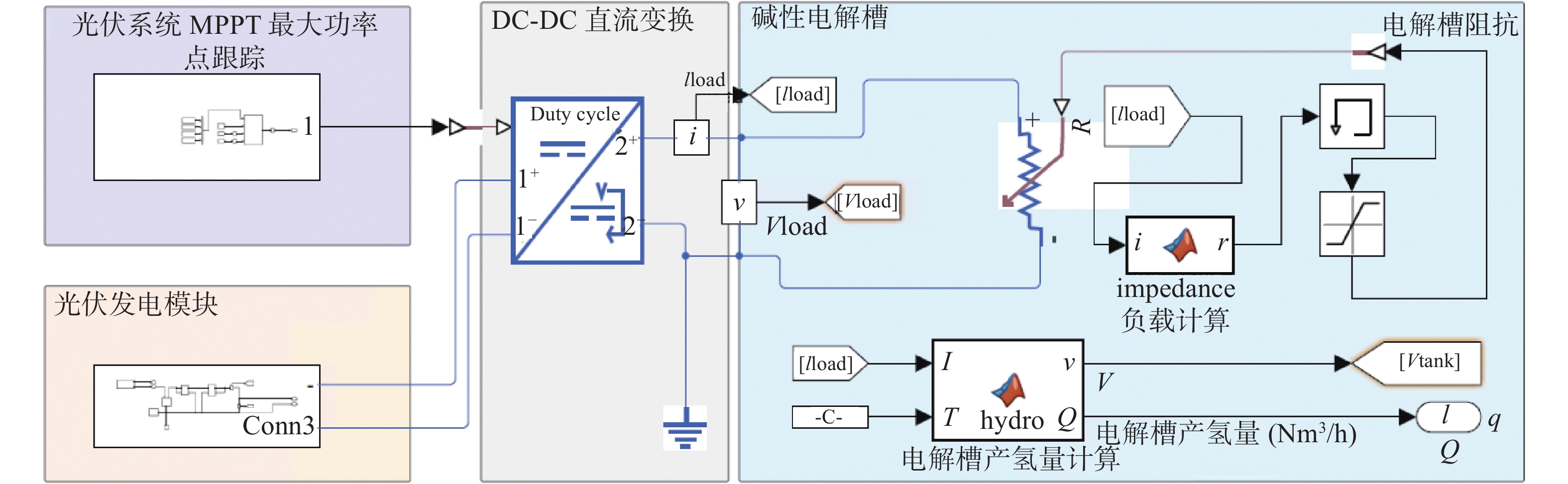
    • 碱性电解水制氢是一种电化学反应,当直流电通过浸入液体或固体电解质中的两个电极会使水分解成氢气和氧气[13]。如图1所示,光伏耦合制氢系统的仿真工作主要分为3块,分别是光伏发电组件、直流电转换控制和电解槽。太阳辐射是光伏系统进行工作的主要能量来源,光伏电池捕捉入射阳光利用半导体的材料特性将光能转化为电能。转化后的电能经直流变流器调节后传输给电解槽[14]。电解槽利用电能将纯水分解为氢和氧分子,并通过管道将氢气收集起来,经过气液处理和纯化后,输送到储罐进行存储,因最终的产物是氢气,所以本研究主要针对系统中的光到电、电到氢的过程进行建模以及仿真[15-16]

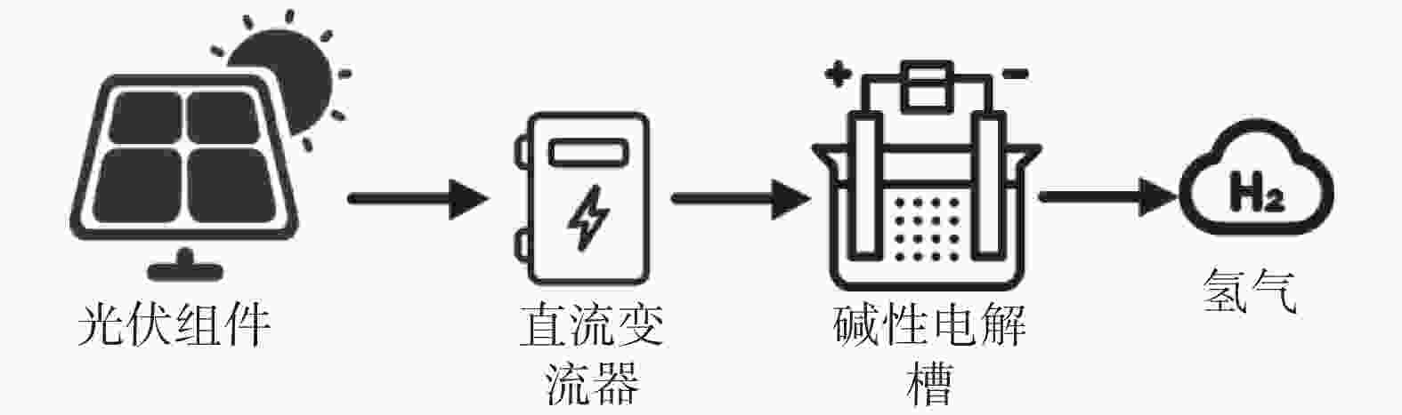
      Figure 1.  Schematic diagram of photovoltaic coupled water electrolysis hydrogen production system

    • 碱性电解槽的仿真建模参考了Tijani[17]等人开发的数学模型,理论基础主要是依据Ulleberg的电解槽热力学模型[18],见式(1)。

      $$ {\rm{{H}_{2}O}}+{\rm{electrical\;energy}}={{\rm{H}_{2}}}+\dfrac{1}{2}{{\rm{O}}}_{2} $$ (1)
      $$ \Delta G=\textit{z}{\rm{F}}{V}_{{\rm{rev}}} $$ (2)
      $$ {V}_{{\rm{rev}}}=\Delta G/\textit{z}{\rm{F}} $$ (3)
      $$ {V}_{{\rm{rev}}}=\dfrac{{237.2\;{\rm{kJ}/{{\rm{mol}}}}}}{2\times{96\;485\;{\rm{C}/{\rm{{mol}}}}}}=1.229\;{\rm{V}} $$ (4)

      式中:

      ∆G ——基伯斯自由能(J/mol);

      z ——电子数量;

      F ——法拉第常数,96485 C/mol。

      Vrev ——可逆过电压(V);

      在电解过程中,小室的工作电压是可逆过电压和激活过电压(即电极响应电压)以及电解质的欧姆过电压的总和 ,见式(5)。Vrev也可以看作是电解过程中所需的最小电压。

      $$ {V}_{{\rm{cell}}}={V}_{{\rm{rev}}}+{V}_{{\rm{act}}}+{V}_{{\rm{ohm}}} $$ (5)
      $$ {V_{{\rm{act}}}} = s\;{\rm{log}}\left( {\dfrac{{t_1 + t_2/T + t_3/{T^2}}}{A}I + 1} \right) $$ (6)
      $$ {V}_{{\rm{ohm}}}=\dfrac{r_1+r_2T}{A}I $$ (7)

      式中:

      Vcell ——小室的工作电压(V);

      Vact ——激活过电压(V);

      Vohm ——电解质的欧姆过电压(V);

      s ——过电压系数(V);

      t1, t2, t3 ——过电压系数(m2/A);

      T ——温度(℃);

      r1, r2 ——与温度相关的欧姆电阻参数(Ω);

      A ——电极面积(m2)。

      Øystein Ulleberg公式:

      $$ V = {V_{{\rm{rev}}}} + s\;{\rm{log}}\left( {\dfrac{{t_1 + t_2/T + t_3/{T^2}}}{A}I + 1} \right) + \dfrac{{r_1 + r_2T}}{A}I $$ (8)

      根据法拉第定律,法拉第效率可以表达为:

      $$ {\eta _{\rm{F}}} = \dfrac{{{{\left( {I/A} \right)}^2}}}{{{f_1} + {{\left( {I/A} \right)}^2}}}{f_2} $$ (9)

      式中:

      I ——电流(A);

      f1, f2 ——与法拉第效率相关的参数(mA2/cm4)。

      摩尔流速(mol/s)为:

      $$ \dot{n}{{\rm{H}}}_{2}={\eta }_{{\rm{F}}}\dfrac{{n}_{{\rm{c}}}I}{\textit{z}{\rm{F}}} $$ (10)

      式中:

      nc——电池数量。

      氢气的体积流量Q(Nm3/h)表示如下:

      $$ Q=\dot{n}{{\rm{H}}}_{2}\mathrm \times 3\;600\mathrm \times 0.022\;414 $$ (11)
    • 光伏组件是由光伏电池串联和并联组成,并根据入射光强的增减改变输出。本研究中,选用了光伏电池的单个二极管等效电路模型作为仿真基础模型。单个电池的电流I与电压V的关系[19]可以表达为:

      $$ I={I}_{{\rm{ph}}}-{I}_{{\rm{o}}}\text{(}{{\rm{e}}}^{\frac{V+{R}_{{\rm{s}}}I}{n{\rm{k}}T/q}}-{1)-}\frac{V+{R}_{{\rm{s}}}I}{{R}_{{\rm{sh}}}} $$ (12)

      式中:

      Iph ——光生电流(A);

      Io ——二极管的反向饱和电流(A);

      n ——理想因子;

      k ——玻尔兹曼常数,1.380649×10−23 J/K;

      T ——光伏电池温度(℃);

      q ——电子电荷(C);

      Rs ——电池内部的串联电阻(Ω);

      Rsh——电池内部的并联电阻(Ω)。

    • 由于材料、制作工艺等原因,组件模型的参数存在差异, 所以建立模型对于组件参数的选择是开放性的,以便于对不同设备进行匹配和模拟。在建立仿真模型的过程中需要确定各组件的参数作为仿真运算的初始量,对于电解槽而言,主要是针对其单一小室的特性参数进行定义。因为电解槽槽体是封装好的部件,在运行过程中,很难取得实际的运行参数,所以一般是由设备厂家提供基础的参数取值。本次研究引用了文献[19]中所提及的设备信息和参数进行仿真模型的建立。相比于电解槽,光伏电池的模型参数更加容易获得,本次研究中直接采用了MATLAB-SIMSCAPE平台内所封装的光伏电池模型参数,参数数值取自设备厂家。

    • 表1中为电解槽生产厂家所提供的电解槽单个小室的特性参数。电解槽槽体是由多个小室串联或并联连接组成。由于连接方式、制作工艺和材料等因素的影响,不同电解槽的特性参数可能存在不同,以产氢量500 Nm3/h的碱性电解槽为例,电解小室的数量一般在180个。对于相似结构的电解槽,所选用的特性参数具有一定的普适性。

      参数符号/单位数值
      反向电压Vrev/V1.229
      单个小室电极面积A/m20.25
      法拉第常数F/(C·mol−1)96485
      电极数量z2
      小室数N180
      电极过电压系数s/V0.185
      电极过电压系数t1/(A−1·m2)1.002
      t2/(A−1· m2 ·℃)8.424
      T3/(A−1· m2 ·℃)247.3
      电解质的欧姆电阻有关的参数r1/(Ω ·m2)8.05e−5
      r2/(Ω·m2 ·℃−1)−2.5e−7

      Table 1.  Characteristic parameters of the electrolyzer

    • 光伏阵列由光伏板组成,光伏板内含有多个光伏电池。表2中为本次研究中所选光伏组件单个电池的特性参数。所选组件由72个电池串联,2组并联组合而成。这些参数将用来计算光伏组件在不同工况下的工作情况。

      参数数值
      开路电压Voc/V0.67918
      短路电流Isc/A5.73
      光生电流IL/A5.73
      二极管的反向饱和电流Io/A1.3195e−7
      二极管理想因子n1.503
      硅的能带宽εg/eV1.12
      并联阻值Rp1443.27
      串联阻值Rs0.00056

      Table 2.  Electrical characteristic parameters of photovoltaic modules

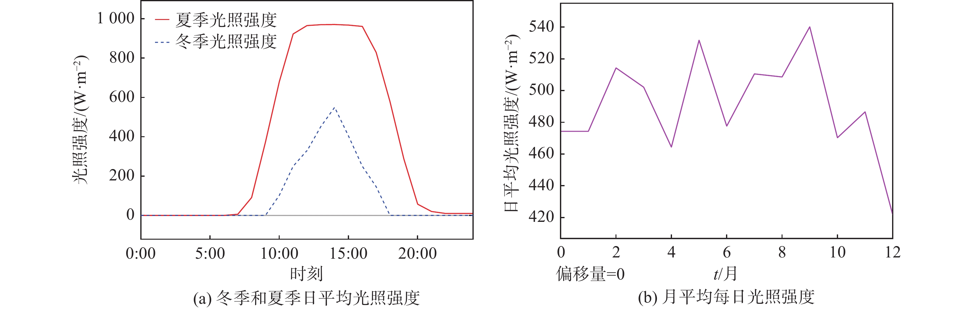
    • 文章参考了某光伏项目在冬季、夏季的单日以及月平均每日的光强分布作为输入条件。从图2中可以看出夏季的总体辐射量要比冬季高且时长更长,每月的日平均辐照强度波动在20%左右。辐照强度将直接影响光伏组件的输出性能。

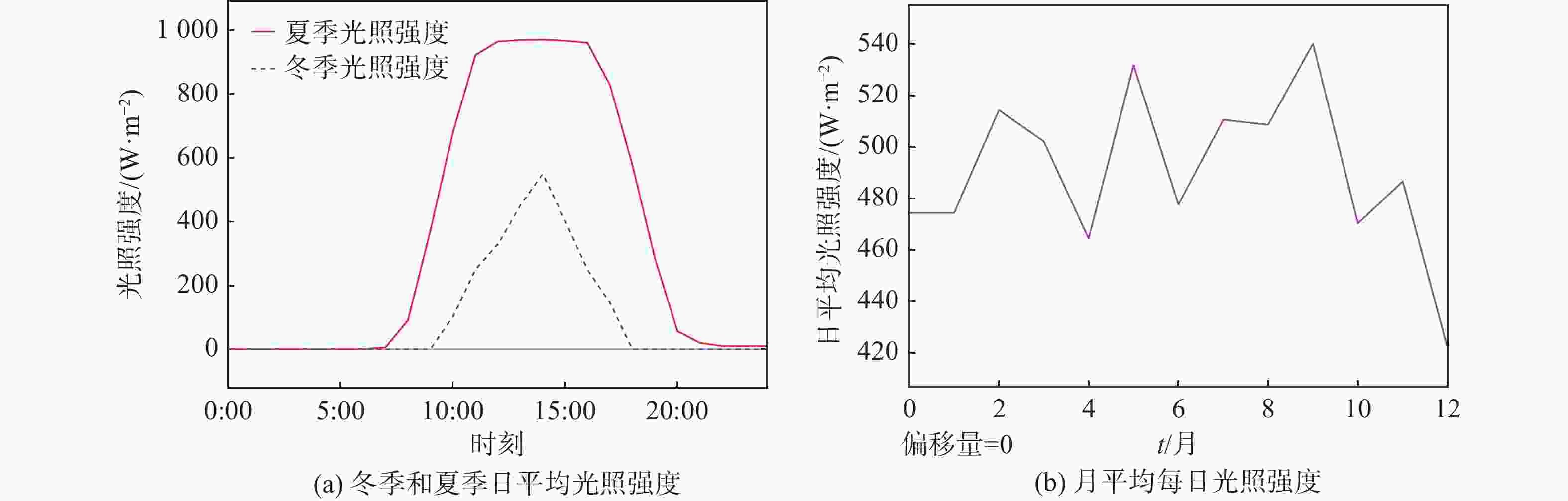
      Figure 2.  Distribution of light intensity

    • 文章中的仿真模型基于MATLAB-SIMSCAPE平台搭建,见图3,部分系统组件通过物理建模形式建立,目的是更好地模拟各组件的电学性能。整个系统主要分为3个部分,分别是光伏阵列、直流变流器和电解槽。光强分布作为输入条件连接至光伏阵列,所设计的光伏阵列由480块光伏板并联和12组光伏板串联组合而成,在标准测试环境(1 kW/m2)下可提供2.5 MW的功率输出。直流变流器连接在光伏阵列和电解槽之间,其功能是根据光强的变化来调节光伏阵列的输出,并实现最大功率点跟踪功能。直流变流器采用的是DC-DC升降压电路,使用扰动观测(Perturb and Observe,P&O)算法来调节电路占空比[20]

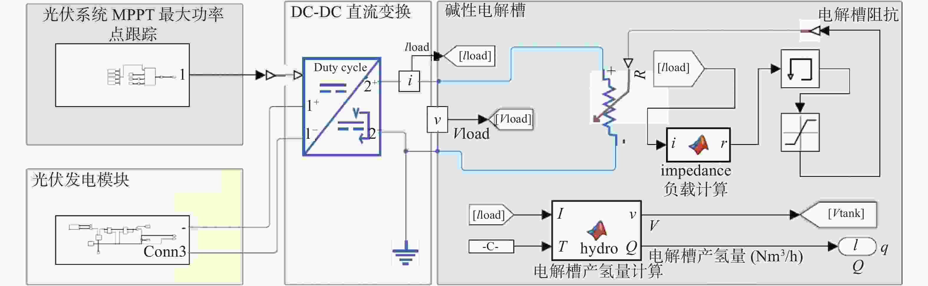
      Figure 3.  Model diagram of photovoltaic coupling hydrogen production system

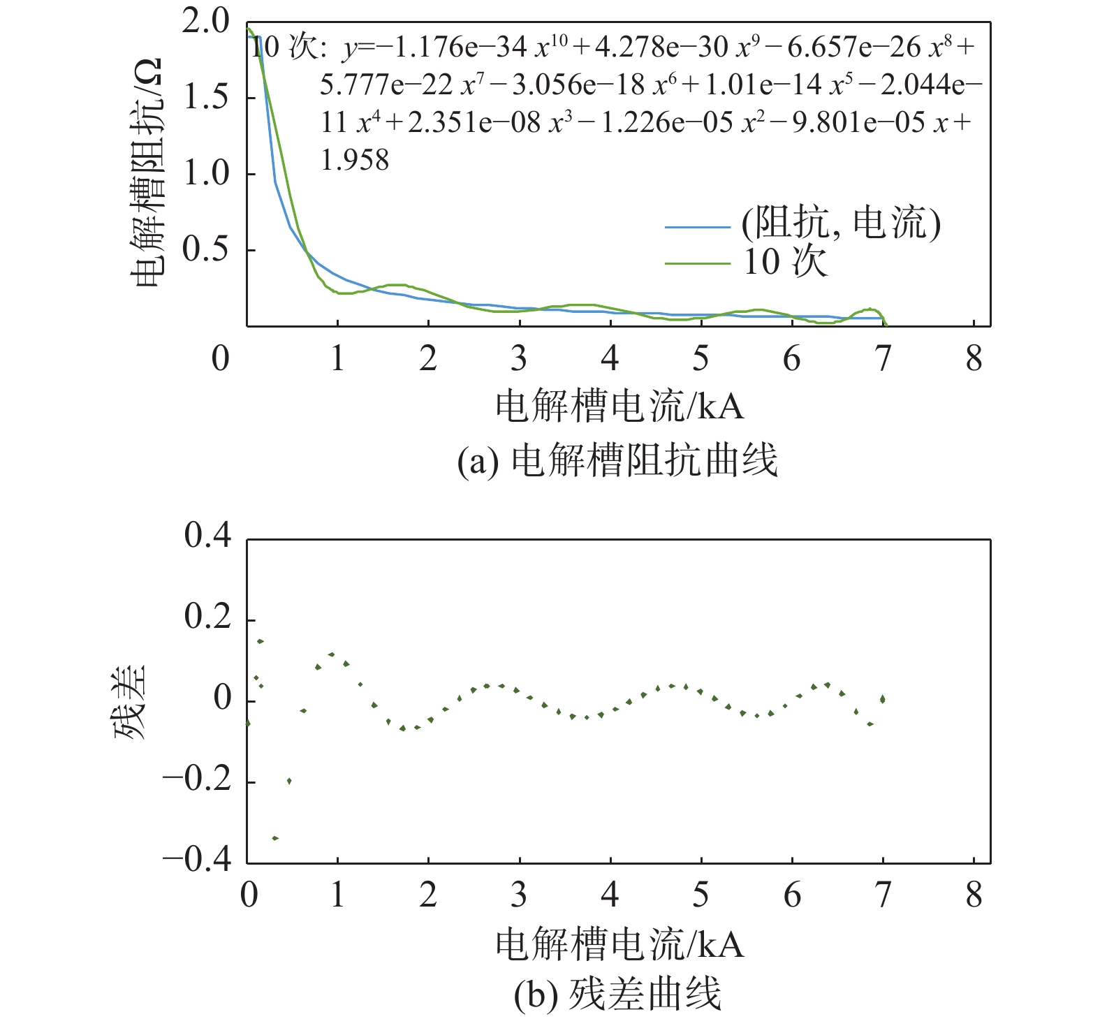
      文章建立了电解槽的仿真模块,将电流和电解槽温度作为输入条件用来计算电解槽的工作电压以及产氢量。为了减少对系统性能分析时的复杂性,本仿真系统未计及直流变流器及线路的损耗。电解槽作为系统的负载需要接入前端的电路,但是电解槽仿真模块作为信号模型无法直接接入到主电路。因此在研究过程中建立了电解槽的等效负载模型接入到主电路当中,并且令电解槽随主电路输出信息联动。等效负载模型是电解槽输入电流和电阻的函数,函数公式通过对电解槽不同出力工况下的曲线拟合求得。如图4所示,利用10次方公式可以较准确地拟合该曲线,其残差值≤±0.2。

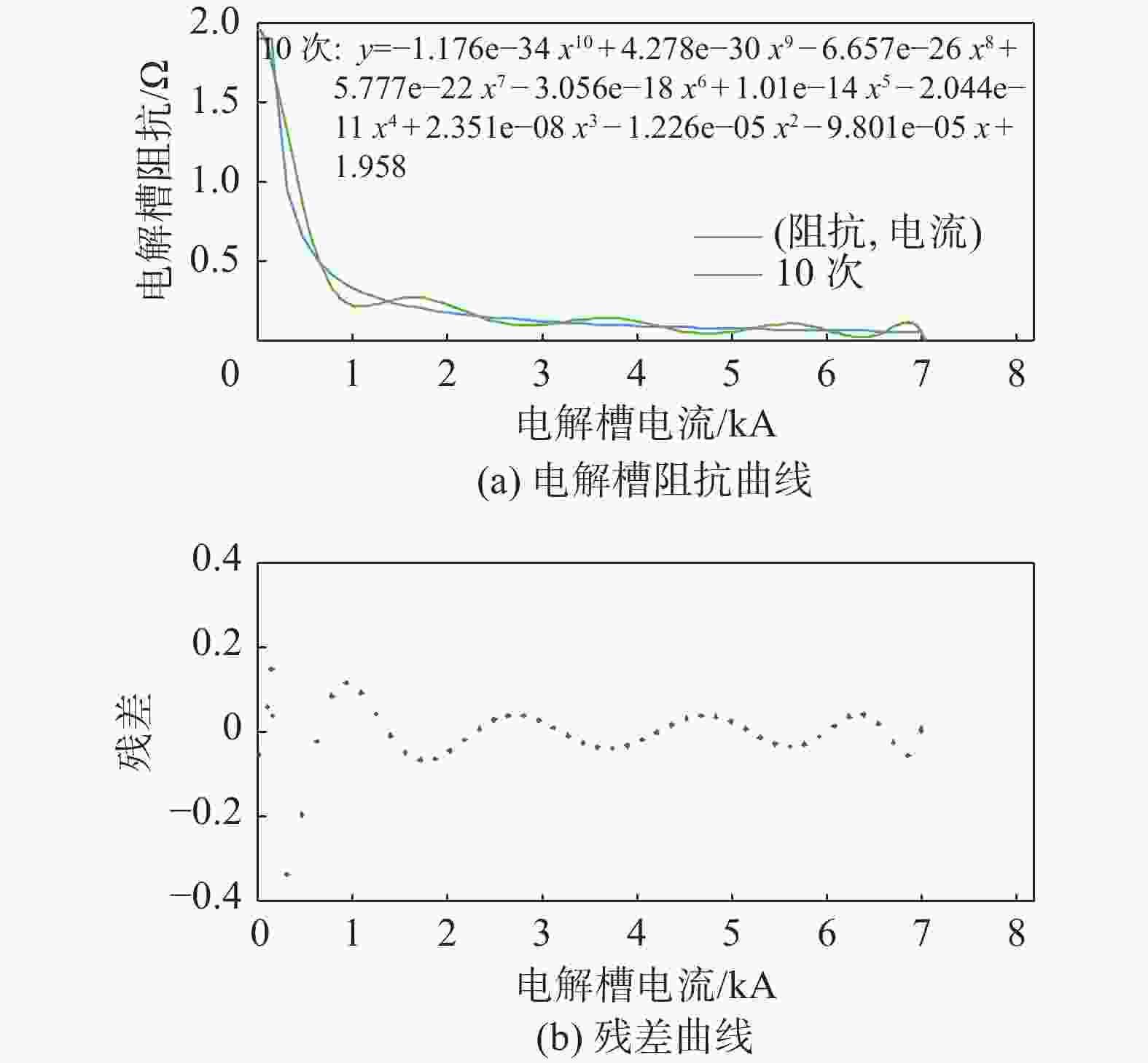
      Figure 4.  Electrolyser equivalent resistance fitting curve

      系统的仿真原理以及过程为:光伏电池根据输入光强的不同产生相应的电流和电压,直流变流器根据输入的不同,控制得到相应的输出电流,电流信息传入电解槽模块用来计算产氢量和电解槽的电压。输入光强变化时,该仿真系统可以实时调整负载运行点以及光伏组件的最大功率输出点,最终实现了光伏耦合电解水制氢系统的过程仿真模拟。

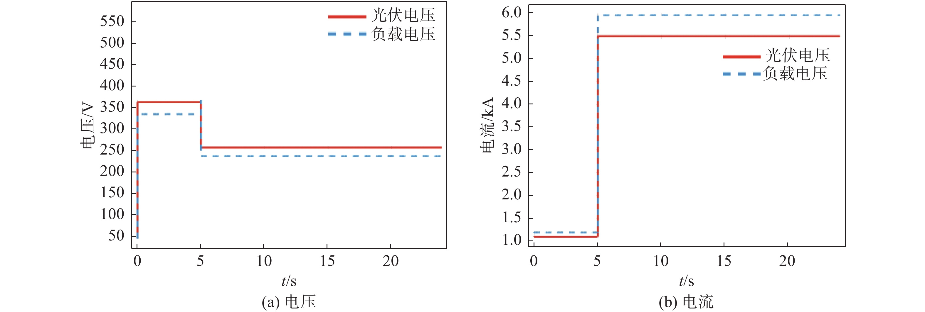
    • 图5给定了系统一组简单的输入光照强度变化用来测试仿真系统的正确性。

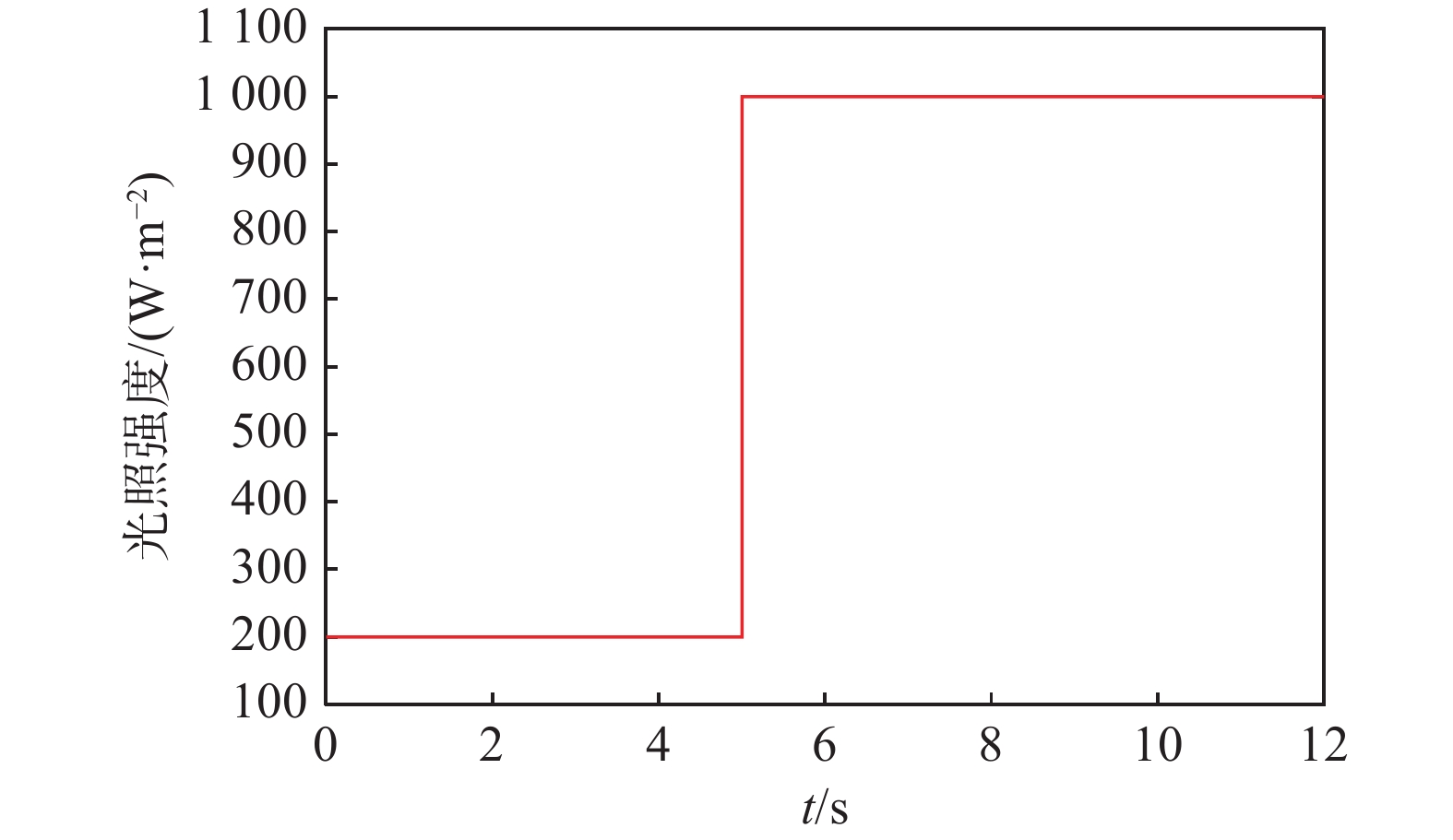
      Figure 5.  Changes in light intensity

      图6所示,光伏组件电流随光照强度的增加而增加,组件电压经直流变流器调节后保持在最大功率点处。在电解槽温度保持不变在80 ℃的情况下,电解槽的电流、电压水平与其等效电阻值挂钩,根据前文拟合曲线可知,当反馈电流增加时,电解槽的等效电阻值将会减小。

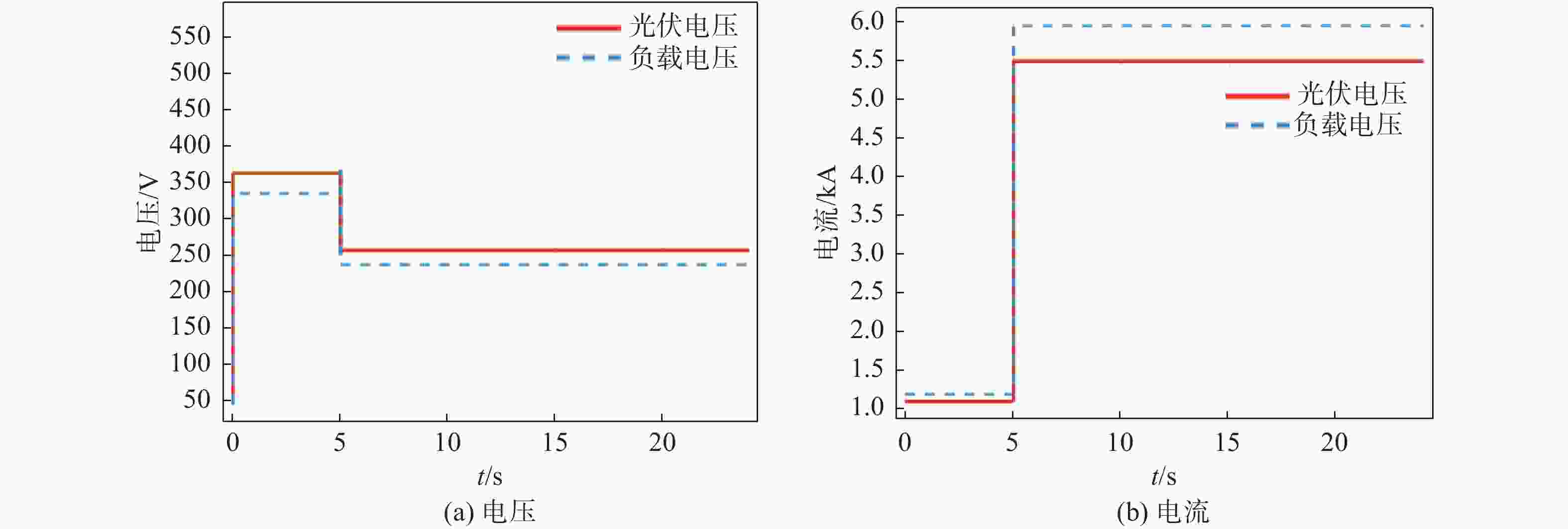
      Figure 6.  Photovoltaic modules and electrolyser voltage and current changes
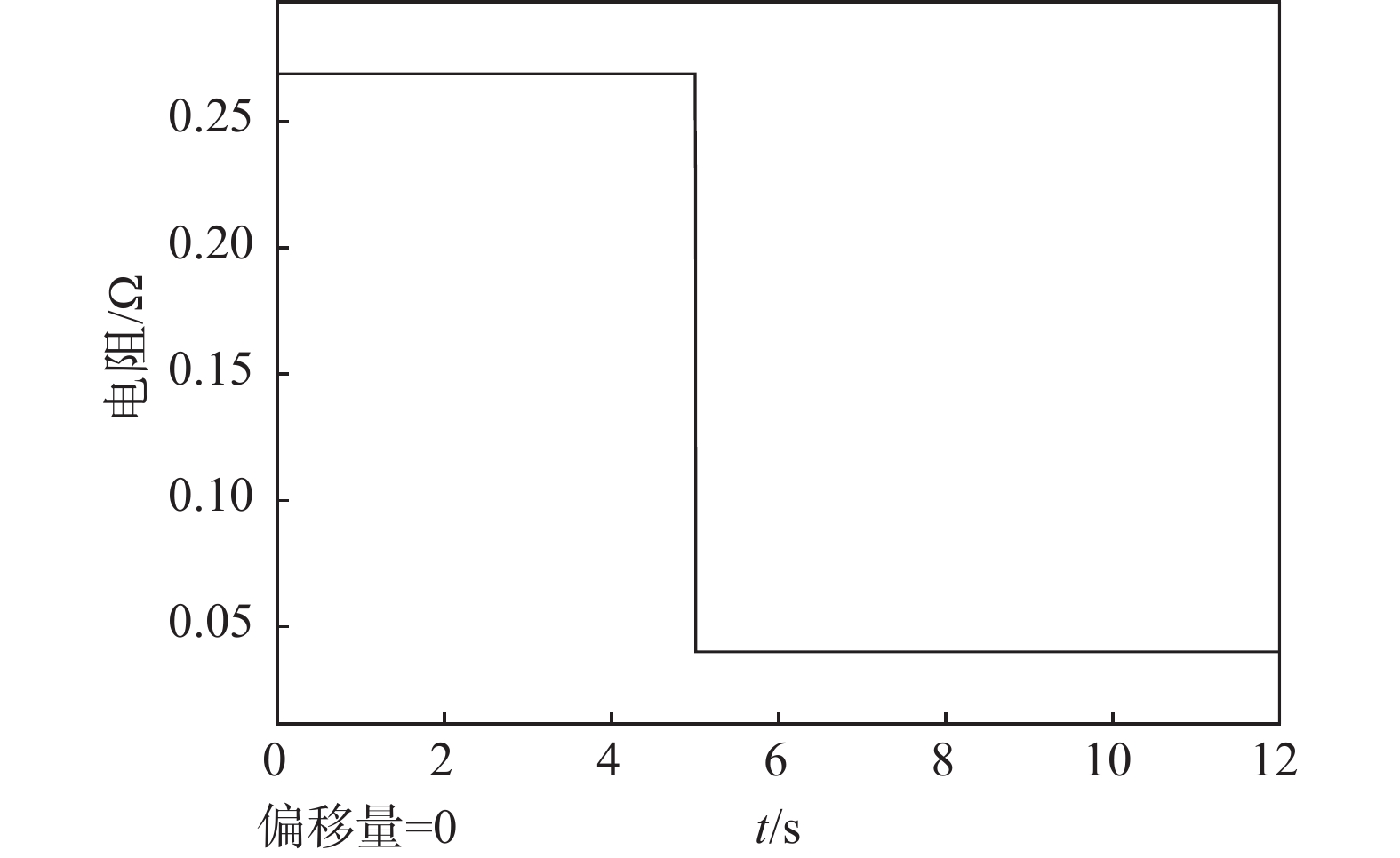
      图7可以看到,电解槽的等效电阻值随电压、电流值变化,仿真结果与理论相符。

      Figure 7.  Change of equivalent resistance of electrolyser

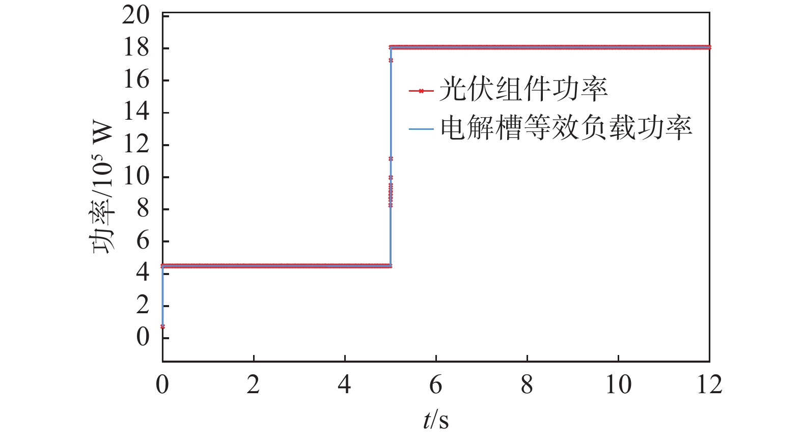
      对直流变流器的控制中,计算占空比时,将会考虑电解槽等效电阻的变化。当电阻减小时会令电解槽电压减少、电流增加,但其总功率会与光伏输出功率持平,如图8所示。

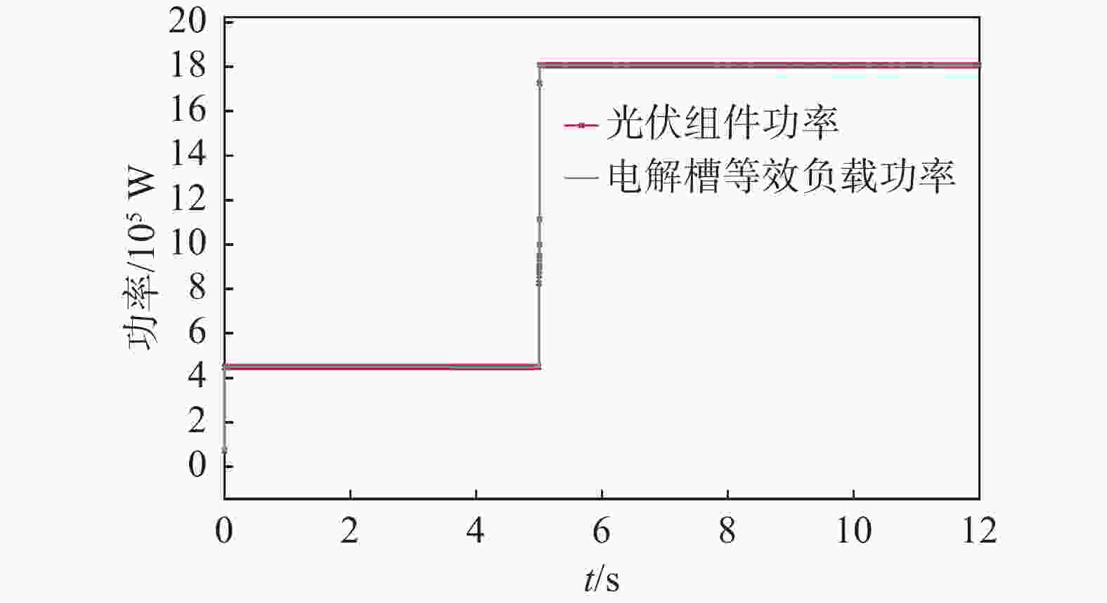
      Figure 8.  Power of the photovoltaic module and electrolyser equivalent resistance

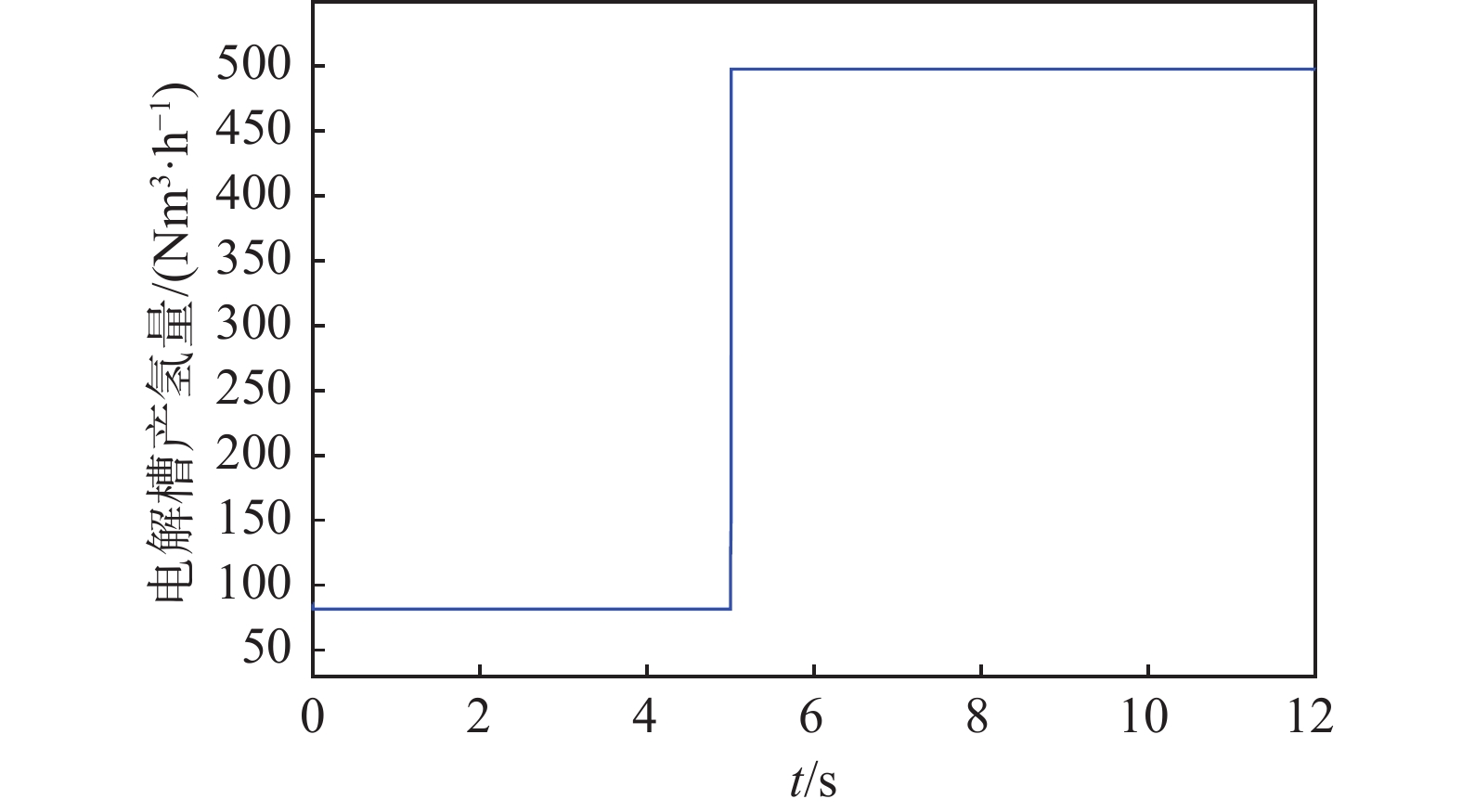
      在无其他电源接入的情况下,电解槽的产氢能力与光伏组件的输出成正比,从图9中可以看到在1 kW/m2的光照强度下2.5 MW的光伏组件的输出可以满足电解槽500 Nm3/h的产氢量,符合工程经验。

      Figure 9.  Hydrogen production rate
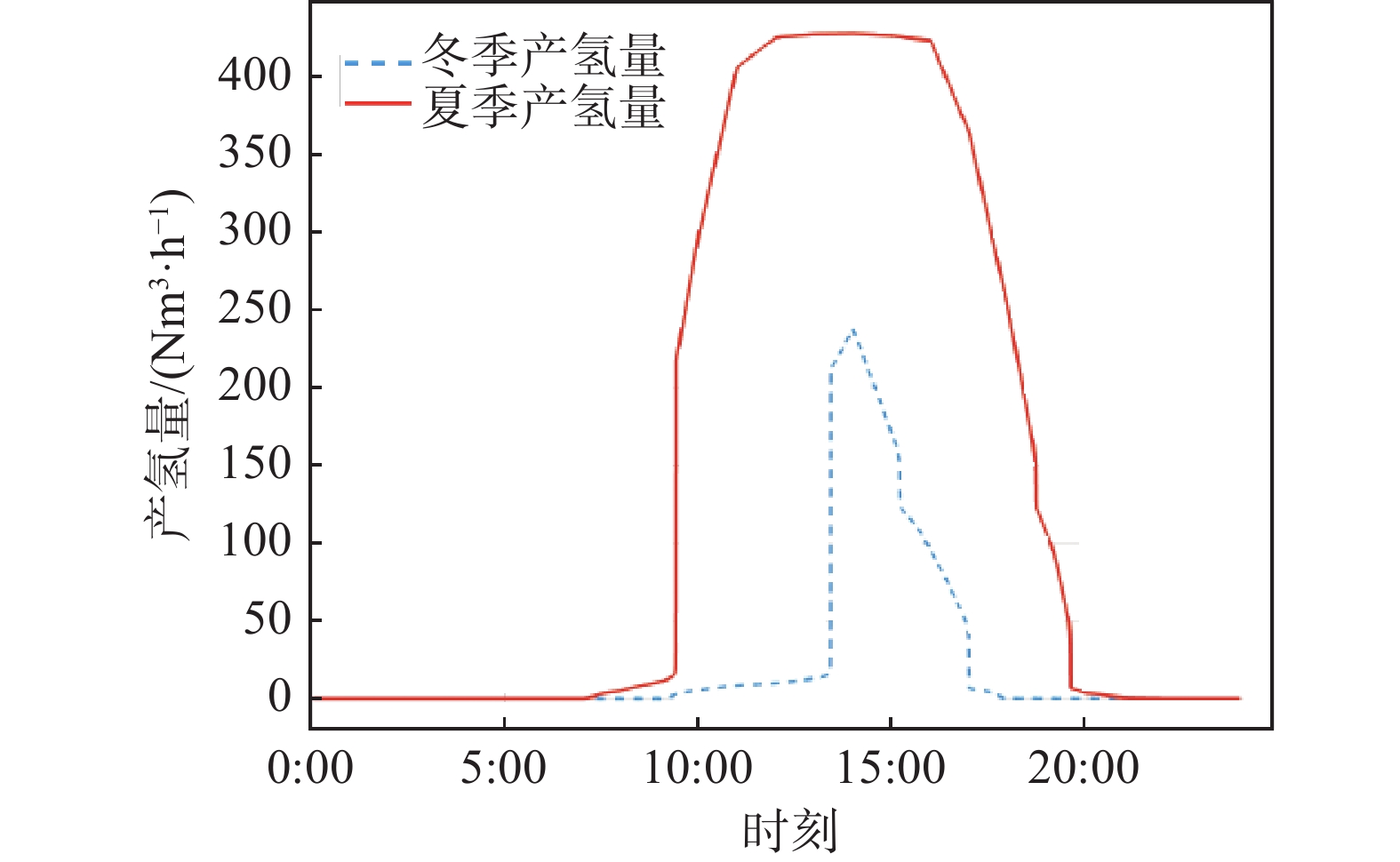
      这里采用实际项目的光照条件,对仿真模型的平均产氢量进行了对比。结合表3图10,系统在夏季的产氢能力要明显高于冬季,这主要是由于冬季光照强度较低且时间较短所造成的。如果考虑设备运行损耗,系统在低光照情况下的产氢能力将会进一步减小。

      夏季产氢时间平均产氢量/Nm3冬季产氢时间平均产氢量/Nm3
      8:00-9:004.7
      9:00-10:0010
      10:00-11:0029710:00-11:005.14
      11:00-12:0040611:00-12:008.38
      12:00-13:0042512:00-13:009.9
      13:00-14:0042713:00-14:00130
      14:00-15:0042714:00-15:00238
      15:00-16:0042615:00-16:00170
      16:00-17:0042316:00-17:0094
      17:00-18:0036417:00-18:006.3
      18:00-19:00251
      19:00-20:00106
      20:00-21:003.4
      总产氢小时数日产氢量//Nm3总产氢小时数日产氢量//Nm3
      133570.18661.72

      Table 3.  Hydrogen production period and production volume in summer and winter

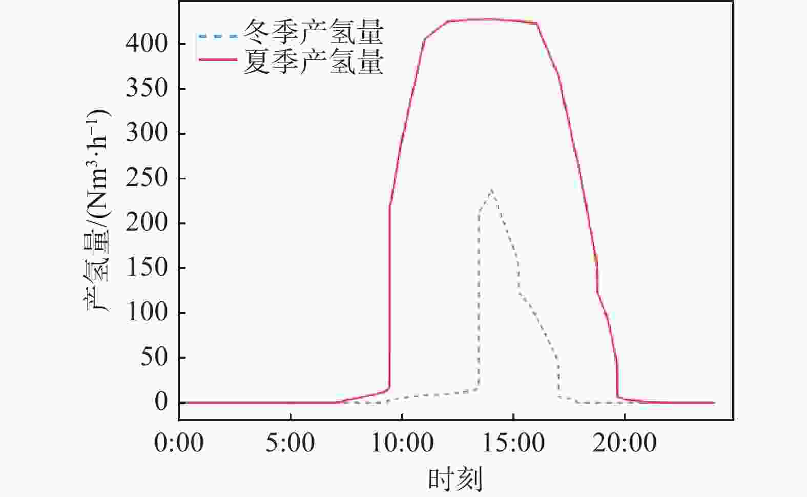
      Figure 10.  The average hydrogen production of electrolyzer in winter and summer

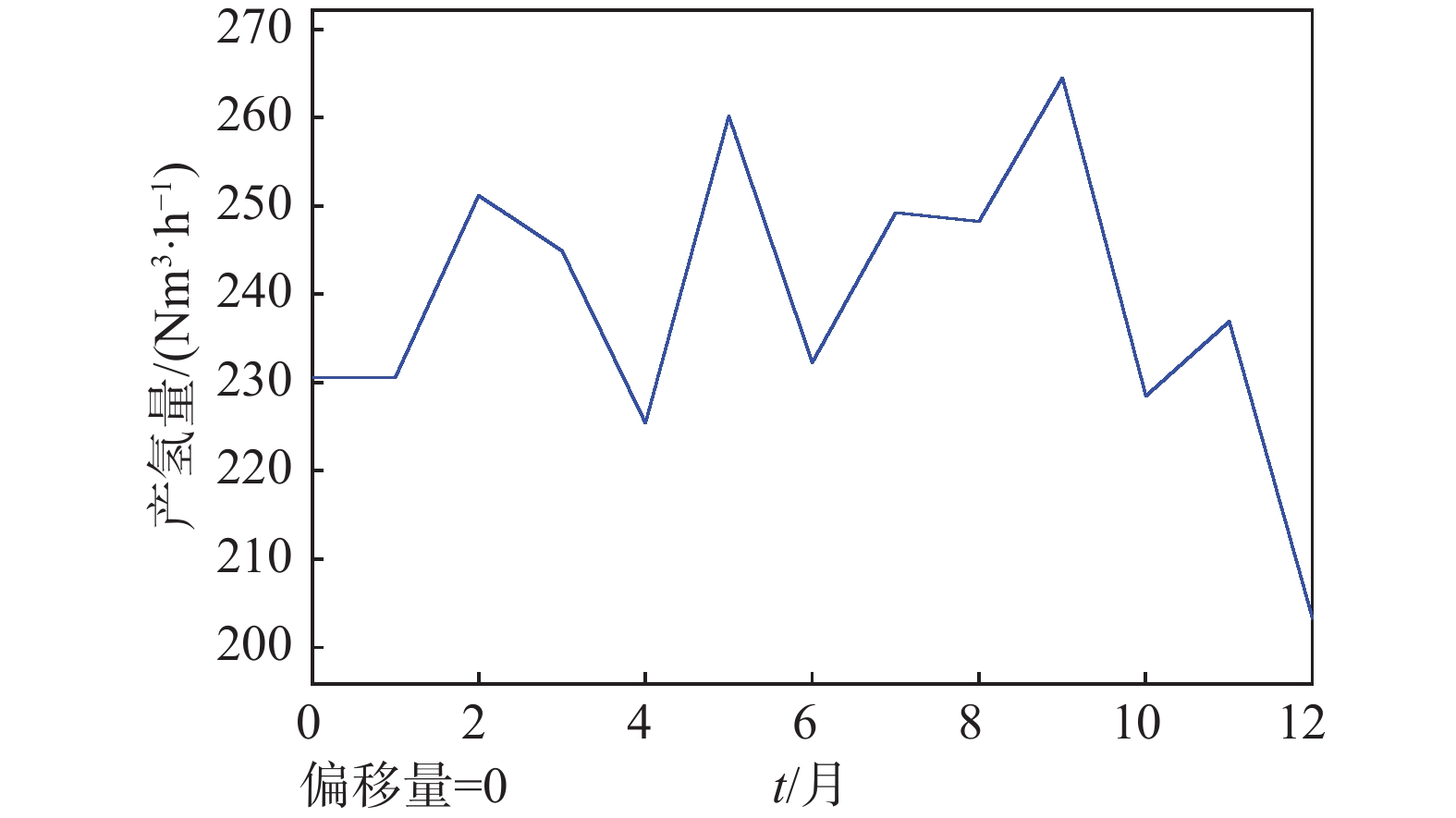
      对每月的日平均产氢量进行了模拟。如图11所示,除12月以外,电解槽的月平均日产氢能力有12%的浮动并保持在240 Nm3/h左右。由于冬季的低入射光强,造成了数值在12月份的降低。参考表4,受每月天数不同和季节的影响,系统的年产氢量为830.131 kNm3,输入某项目的实际数据,可输出符合工程实际数据。

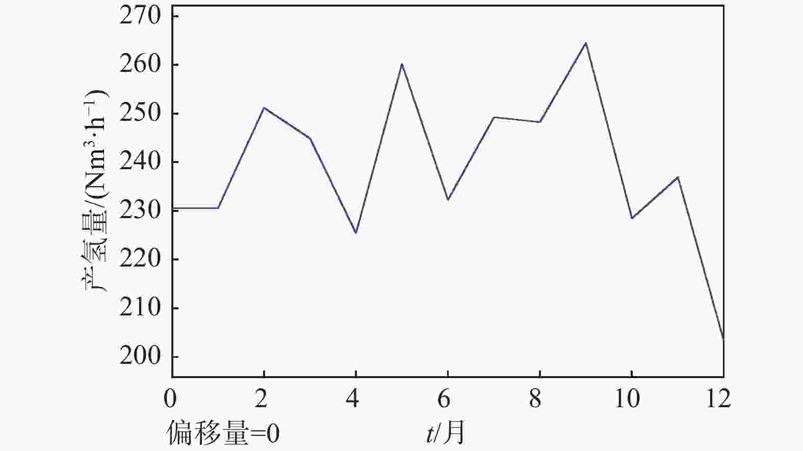
      Figure 11.  Electrolyzer average daily hydrogen production for each month

      月份每月产氢量/kNm3月份每月产氢量/kNm3
      168.030773.331
      266.766873.036
      372.153975.240
      464.4101067.146
      576.5701167.545
      666.1201259.784
      年产氢量/kNm3830.131

      Table 4.  Monthly average hydrogen production rate

    • 本研究针对光伏耦合电解水制氢系统提出了一种改进的建模方式,通过构建电解槽等效电阻的方式解决了信号传递方式不统一,模拟过程复杂等问题。系统模型可以适应光伏电源的波动从而进行动态负载调节,电解槽负载拟合残差值≤±0.2。通过代入实际项目的天气数据,模拟了不同工况下的电解槽平均产氢能力。研究成果可为可再生能源电解水制氢整体系统的运行状态的评估提供参考,对于实现电解槽参数的优化同样具有工程价值。目前在本次研究中,只考虑了电解槽的电气特性,所以设定了电解槽的工作温度保持在80 ℃不变,未来的工作将会把电解槽的温升特性和储氢系统作为研究重点并加入到仿真过程当中。

Reference (20)

Catalog

    /

    DownLoad:  Full-Size Img  PowerPoint
    Return
    Return