
-
先进托克马克装置的一个重要特性是具有非单调安全因子剖面,能够提供负磁剪切[1-2]。负磁剪切位形存在多个${q_s} = m/n$的共振有理面,这样的有理面上能够引起双撕裂模不稳定性[3]。因此双撕裂模的研究,尤其是其非线性发展的特性的研究[4-7],对于探索和解决先进托克马克装置诸如内部输运垒的形成机制的一些问题,会有积极的帮助。由电阻引起的双撕裂模的非线性行为[8-11]已经被很多学者研究过。王正汹等人用数值方法,给出了平板位形下两个有理面距离为中等距离的电阻双撕裂模的非线性演化[12-14],认为双撕裂模非线性演化大概可以分为4个阶段。KONOVALOV在DⅢ-D中的实验[15]指出,由于准稳小幅度电磁扰动,在托卡马克等离子体中会存在反常电子粘滞性。这时候,作为耗散效应,反常电子粘滞性也能引起撕裂模不稳定性。由反常电子粘滞性引起的撕裂模被认为是引起破裂不稳定性的可能原因之一[16]。电子粘滞撕裂模也被作为在实验上观察到的快锯齿破裂的可能原因[17]而被研究。董家齐[18]用解析的方法,研究了平板位形等离子体中由反常电子粘滞性引起的双撕裂模的线性行为。何志雄[19]用数值模拟的方法,在直圆柱位形下,研究了由反常电子粘滞性引起的双撕裂模的线性发展。
-
(1)撕裂模MHD方程的推导
考虑圆柱位形的简化磁流体动力学(RMHD)方程,用大环径比近似和低-β展开,可以用两个标势,磁通量函数Ψ(G·cm2)和流函数Φ(cm3/s)来表示磁场和等离子体速度:$ \bar B = {B_0} - \nabla \varPsi \times \bar \varphi $,$ \bar \upsilon = {\upsilon _0} + \nabla \varPhi \times \bar \varphi $,包含电子粘滞项的欧姆定律:
$$ \vec E + \frac{{\text{1}}}{{{c}}}\vec \upsilon \times \vec B = \eta \vec j - \frac{{{m_{{e}}}{\mu _{{e}}}}}{{{n_{{e}}}{{\text{e}}^{\text{2}}}}}\nabla _ \bot ^2\vec j $$ (1) 运动方程可以写成:
$$ \rho \left[ {\frac{{\partial \vec \upsilon }}{{\partial t}} + (\vec \upsilon \cdot \nabla )\vec \upsilon } \right] = - \nabla P + \frac{{\text{1}}}{{{c}}}\vec j \times \vec B + {\mu _i}{\nabla ^2}\vec \upsilon $$ (2) 式中:
$ \vec B $ ——磁场强度(G);
$ \vec E $ ——电场强度(G);
$ \vec \upsilon $ ——磁流体元速度(cm/s);
$ \vec j $ ——电流密度(emu/cm2);
$e$ ——电子电荷(esu);
$ {m_{\mathrm{e}}} $——电子质量(g);
$ \eta $ ——等离子体电阻(Ω);
$ {\mu _{\mathrm{e}}} $——平行电子粘滞性[emu·s/(g·cm)];
$ \rho $——等离子体质量密度(g/cm3);
$ {\mu _i} $——离子粘滞性[g/(cm·s)]。
简化方程式(1)和式(2)并归一化(无量纲)后得到撕裂模MHD方程:
$$ \frac{{\partial \psi }}{{\partial t}} = - [\psi ,\phi ] + {S^{ - 1}}\hat \nabla _ \bot ^2\psi - {R^{ - 1}}\hat \nabla _ \bot ^2(\hat \nabla _ \bot ^2\psi ) + {\hat E_{{\mathrm{wz}}}} - \frac{{\partial \phi }}{{\partial \zeta }}, $$ (3) $$ \frac{\partial }{{\partial t}}(\hat \nabla _ \bot ^2\phi ) = [\hat \nabla _ \bot ^2\psi ,\psi ] - \frac{\partial }{{\partial \zeta }}(\hat \nabla _ \bot ^2\psi ) - [\hat \nabla _ \bot ^2\phi ,\phi ] + R_\mu ^{ - 1}\hat \nabla _ \bot ^2(\hat \nabla _ \bot ^2\phi ), $$ (4) 这里,归一化参量为($ a,{\tau _{\mathrm{h}}},{B_0} $),并定义极向角$ \zeta \equiv z/{R_0}q(a) $,于是有归一化的磁通量函数$ \psi = \varPsi /a{B_0} $,流函数$ \phi = \varPhi /({a^2}/{\tau _{\mathrm{h}}}) $,电阻磁雷诺数$ S \equiv {\tau _{\text{η}}}/{\tau _{\mathrm{h}}} $,电子磁雷诺数$ R \equiv {\tau _{\text{υ}} }/{\tau _{\mathrm{h}}} $,离子磁雷诺数$ {R_{\text{μ}} } \equiv {\tau _{\text{μ}} }/{\tau _{\mathrm{h}}} $,$ {\tau _{\text{η}} } = {4{\text{π}}}{a^2}/{\text{η}} {c^2} $,$ {\tau _{\text{υ}} } = {4{\text{π}}}{a^4}{n_e}{e^2}/({m_e}{\mu _e}{c^2}) $,$ {\tau _{\text{μ}}} = \rho {a^2}/{\text{μ}} $。
Poisson括号定义为$ [a,b] = \dfrac{1}{r}\left( {\dfrac{{\partial a}}{{\partial r}}\dfrac{{\partial b}}{{\partial \theta }} - \dfrac{{\partial b}}{{\partial r}}\dfrac{{\partial a}}{{\partial \theta }}} \right) $。
式中:
$ a $ ——托卡马克小半径(cm)
$ {B_0} $——$ {R_0} $处的磁场大小(G);
$ {\tau _h} $ ——宽为$a$的等离子体片的Alfven时间(s);
将函数在$ \theta ,\varphi $方向做Fourier展开:
$$ \psi = {\psi _0}(r) + \sum\limits_{n = 0}^N {} \psi _{np,n}^c(r)\cos [n(p\theta + \varphi )] + \psi _{m,n}^s(r)\sin [n(p\theta + \varphi )] $$ (5) $$ \phi = \sum\limits_{n = 0}^N {} \phi _{np,n}^c(r)\cos [n(p\theta + \varphi )] + \phi _{m,n}^s(r)\sin [n(p\theta + \varphi )] $$ (6) 这里,$p = m/n = {\mathrm{const}}$,$ {\psi _0} $是当$ \dfrac{{\partial \psi }}{{\partial t}} = 0 $和$ \dfrac{{\partial \phi }}{{\partial t}} = 0 $时的平衡量,其他的是扰动量,$ M,N $是$ \theta ,\varphi $方向所取的最大谐波数。将式(5)和式(6)应用到式(3)和式(4),利用Fourier级数的正交关系,得到一组关于扰动量的偏微分方程组。简记为算子形式:
$$ \frac{{\partial Y}}{{\partial t}} = NL(Y) + L(Y) $$ (7) (2)方程数值化
对非线性部分有关时间的差分过程用二阶Adams-Bashforth显示格式,另外用半隐式格式于线性算子:
$$ {Y^{t + \Delta t}} - {Y^t} = \frac{{\Delta t}}{2}[L({Y^{t + \Delta t}}) + L({Y^t})] + \frac{{\Delta t}}{2}[3NL({Y^t}) - NL({Y^{t - \Delta t}})] $$ (8) 因此得到下面代数方程:
$$ \begin{split} &Y\frac{{t + \Delta t}}{p} - \frac{{\Delta t}}{2}L({Y^{t + \Delta t}}) = Y\frac{t}{p} + \frac{{\Delta t}}{2}L({Y^t}) +\\& \dfrac{{\Delta t}}{2}[3NL({Y^t}) - NL({Y^{t - \Delta t}})] \end{split} $$ (9) 极向平衡通量$ {\psi _0}(r) $可由安全因子$ q(r) $给出,其计算关系:
$$ \frac{{{\mathrm{d}}{\psi _0}(r)}}{{{\mathrm{d}}r}} = - \frac{r}{{q(r)}} $$ (10) 而安全因子剖面则参考文献[6]给出:
$$ q(r) = {q_{\mathrm{c}}}{\{ 1 + {\left( {\dfrac{r}{{{r_0}}}} \right)^{2\lambda }}\} ^{1/\lambda }}[1 + A\exp \{ - {\left( {\dfrac{{r - {r_\delta }}}{\delta }} \right)^2}\} ] $$ (11) 根据方程(9),采用差分方法,编写了一个数值代码《RDTM》,进行了网格无关乎验证,即当前网格数下再增加网格点数,数值结果在我们要求的精度内无差别。利用此代码进行数值模拟。
参量固定如下:$ \lambda = 1 $,$ {r_0} = 0.412 $,$ \delta = 0.273 $,$ {r_\delta } = 0 $,$ A = 3 $。用$ {q_{\mathrm{c}}} $来做调控参数,对于具体的$ {q_s} = m/n $,控制初始条件两个有理面的间距$ {D_{12}} $。
螺旋通量$ \psi _p^ * $和极向通量$ \psi $有如下关系[20]:
$$ \begin{split} &\psi _p^ * = - p[({\psi _0} + \psi _{0,0}^c + \sum\limits_\ell ^M {} \psi _{\ell p,\ell }^c\cos (\ell (p\theta + \varphi )) + \\&\psi _{\ell p,\ell }^s\sin (\ell (p\theta + \varphi ))] - \frac{1}{2}({r^2} - 1) \end{split} $$ (12) 假设初始扰动有如下形式:
$$ \tilde \psi (t = 0) = \frac{1}{2}\sum\limits_m {{\psi _{0m}}r(r - 1){e^{i(m{\vartheta _*} + {\vartheta _{0m}})}}} + c.c. $$ (13) 这里,${\psi _{0m}}$是扰动振幅,${\vartheta _*} \equiv \vartheta - q_s^{ - 1}\zeta $是环向角坐标,${\vartheta _{0m}}$是初始相位,在数值计算里,取${\psi _{0m}} = {10^{ - 7}}$,${\vartheta _{0m}} = 0{\text{ }}$。
-
令$ {S^{ - 1}} = 0 $,忽略电阻的作用,研究单独由反常电子粘滞性引起的双撕裂模的非线性发展的演化。在数值结果中发现,两个有理面的间距不同,双撕裂模有不一样的非线性发展阶段。下面就以3个特例来研究不同有理面距离的双撕裂模非线性阶段各自的特征。研究有理面${q_s} = 3$的情况,利用式(11)选择合适的参数,得到对应有理面距离分别为0.40、0.22、0.06初始平衡位形。
-
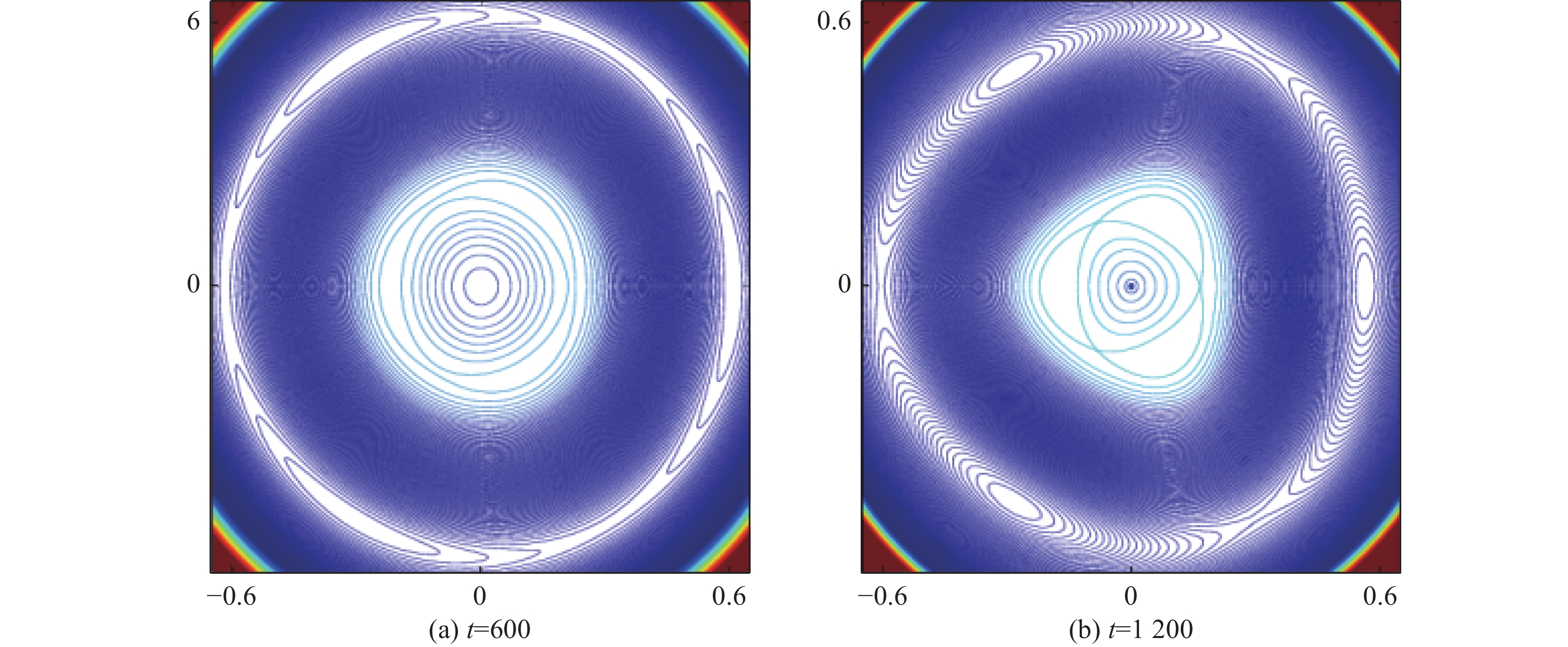
图1显示的是两个有理面距离${D_{12}} = 0.40$、电子磁雷诺数$R = {10^7}$时,系统的磁场位形随时间演化的过程。图1(a)显示t=600时刻两个有理面上磁岛的生长情况。两个有理面分别在径向r1=0.18和r2=0.58的位置。根据有理面的性质可知,在有理面的两边磁场方向相反,所以中间区域(0.18 < r < 0.58)的磁力线与两边r<0.18和r>0.58的磁力线方向相反。这样在磁场重联的初始阶段,有理面两边的磁力线断裂并重新联接,导致在两个有理面上产生磁岛。在这个阶段里,磁岛在生长,其宽度随时间不断地增加,两个有理面上磁岛分形线被中间开放的磁力线所分离。可以发现,当两边的磁岛增长到一定程度的时候,就处于饱和状态,如图1(b)所示,在一定的时间尺度内,不再有变化。也就是说,当两个有理面距离足够大时,双撕裂模的行为更像是分别在两个有理面上独自发展的两个单撕裂模,跟线性理论相符合。
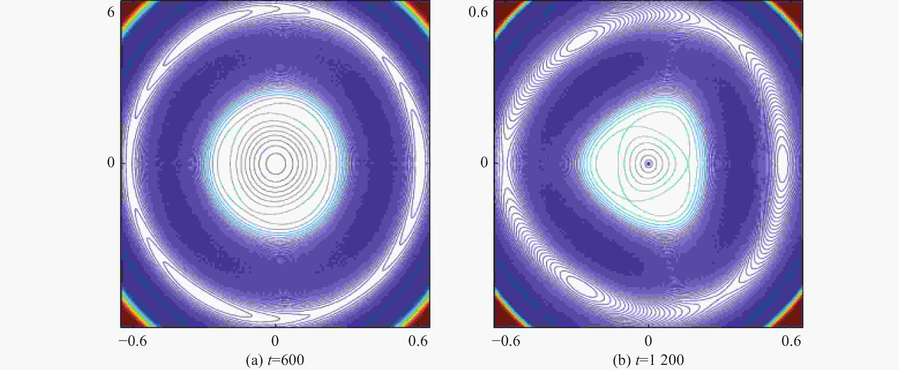
Figure 1. Contour plots of the helical magnetic flux
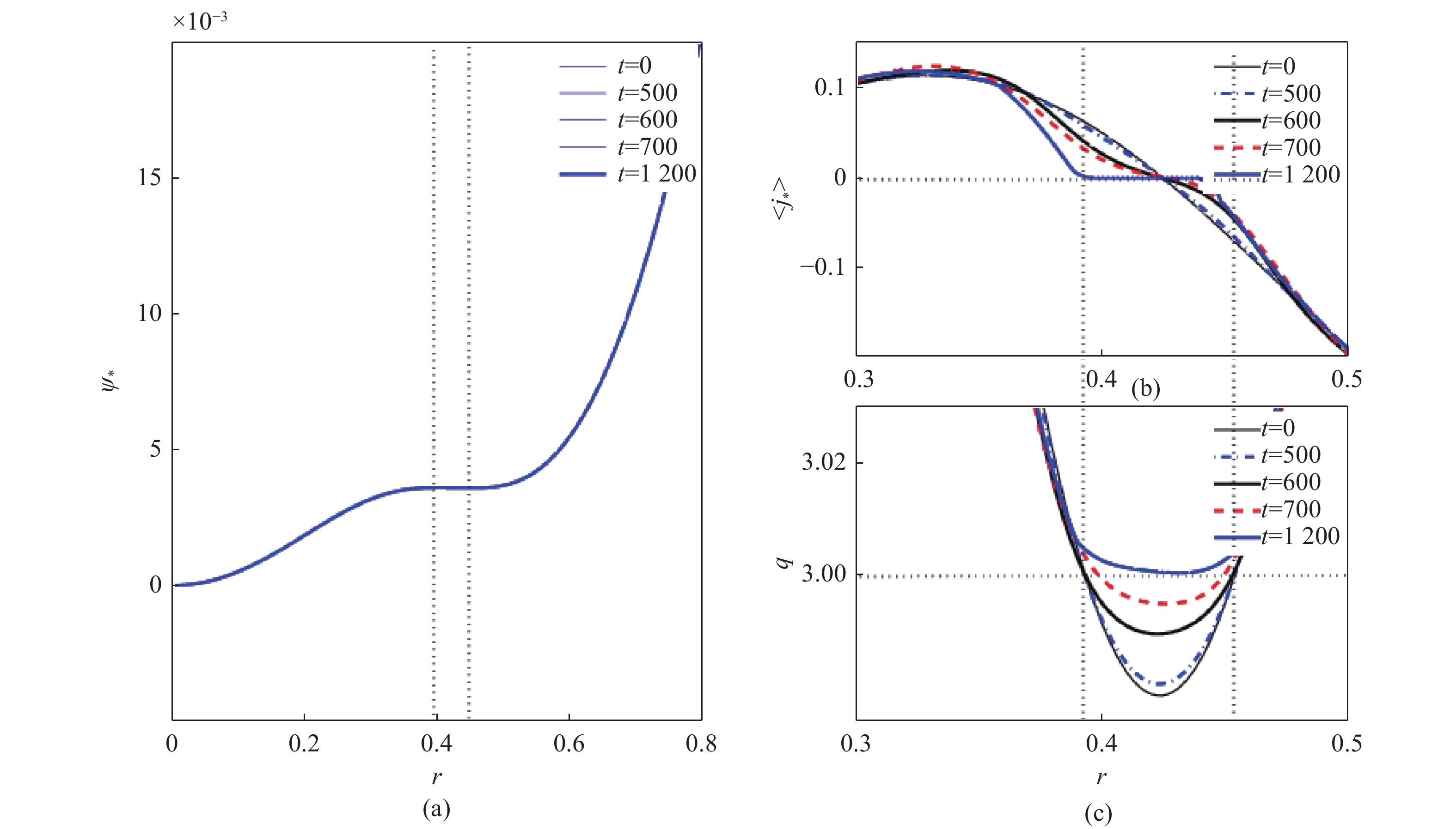
再来看这种情况下螺旋通量$ \psi _p^ * $、安全因子剖面$q(r)$以及${j_*} \equiv {[ - \nabla _ \bot ^2{\psi _*}]_{0,0}} = {j_{0,0}} - 2/{q_s}$。图2所示t=0时刻和t=1 200时刻3个物理量的各自的径向分布。很明显,在这种情况下,他们基本无变化,这也表明,有理面的位置无变化,因此磁岛达到饱和之后,在一定时间尺度内,将保持稳态。
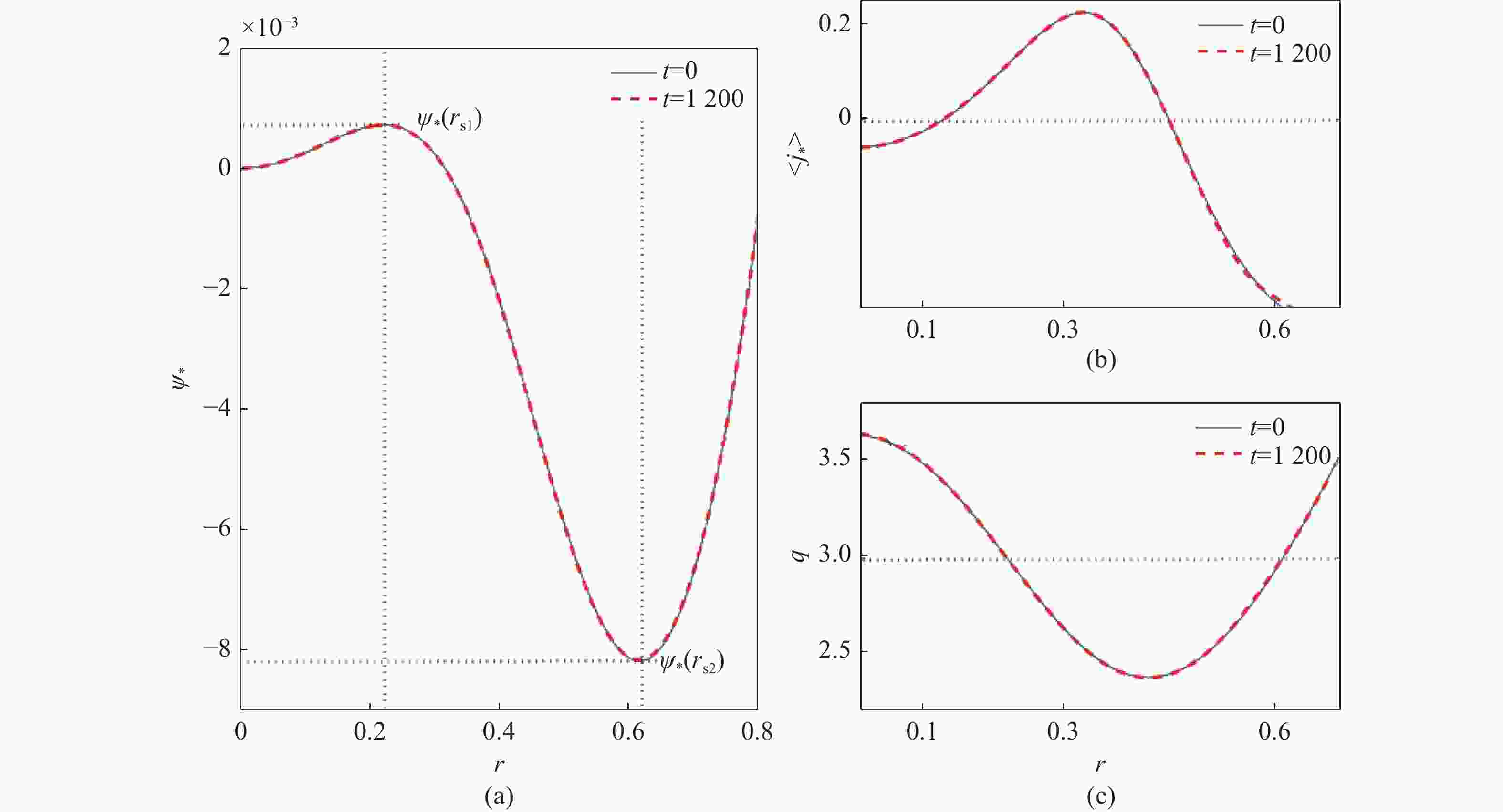
Figure 2. (a) the helical magnetic flux profile, (b) the toroidal current profile and (c) the safety factor profile
-
图3显示的是两个有理面距离${D_{12}} = 0.22$,电子磁雷诺数$R = {10^8}$时,系统的磁场位形随时间演化的过程,两个有理面分别在径向r1=0.33和r2=0.55的位置。图3(a)表示在两个有理面上的磁岛各自在发展,并且被中间的开放磁力线所分离。再次强调的是,两侧的开放磁力线和中间的开放磁力线是反向的。随着磁岛宽度的增大,当中间的反向开放磁力线被联完的时候,t=640,如图3(b)所示,外侧有理面的磁岛分形线内侧跟内侧有理面的磁岛分形线外侧是同向的,所以他们重合了,这时候磁岛的宽度最大。
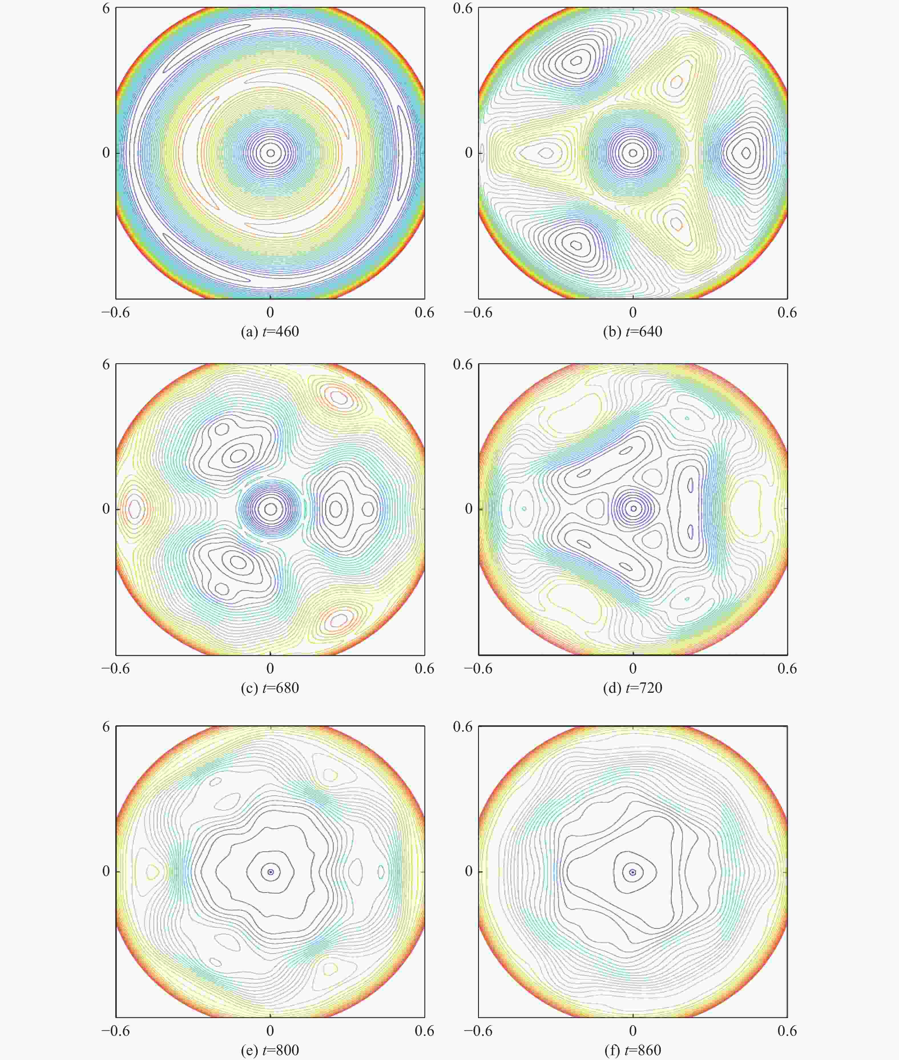
Figure 3. Contour plots of the helical magnetic flux
由于内外侧磁岛相位的错落,可以看到,内侧磁岛联完中间反向的开放磁力线后,整体位置外移,相对应的,外侧磁岛则向内移动,如图3(b)和图3(c)所示。当系统继续往下发展的时候,磁岛的闭合磁力线与两侧平衡开放磁力线开始发生重联:原内侧磁岛与外侧平衡磁力线重联,而原外侧磁岛则与内侧平衡磁力线重联。因为两侧平衡开放磁力线与中间的开放磁力线是反向的,所以跟前述与中间开放磁力线重联会让磁岛增大的情况相反,此时的重联,会让磁岛减小逐渐的湮灭。还有值得注意的是,此时的重联,又重新在原内外两侧磁岛之间产生开放磁力线,如图3(c)所示,原内侧磁岛在外,原外侧磁岛在内,他们交换了彼此的径向位置。
原磁岛交换位置后会湮灭,同时,在不同的位置又会产生新的比较弱的磁岛,如图3(d)和图3(e)所示,重复着较弱的增长与湮灭的过程,直至t=860时刻,可以看到,磁岛基本消失了。最终结果就是系统的磁力线方向都相同。
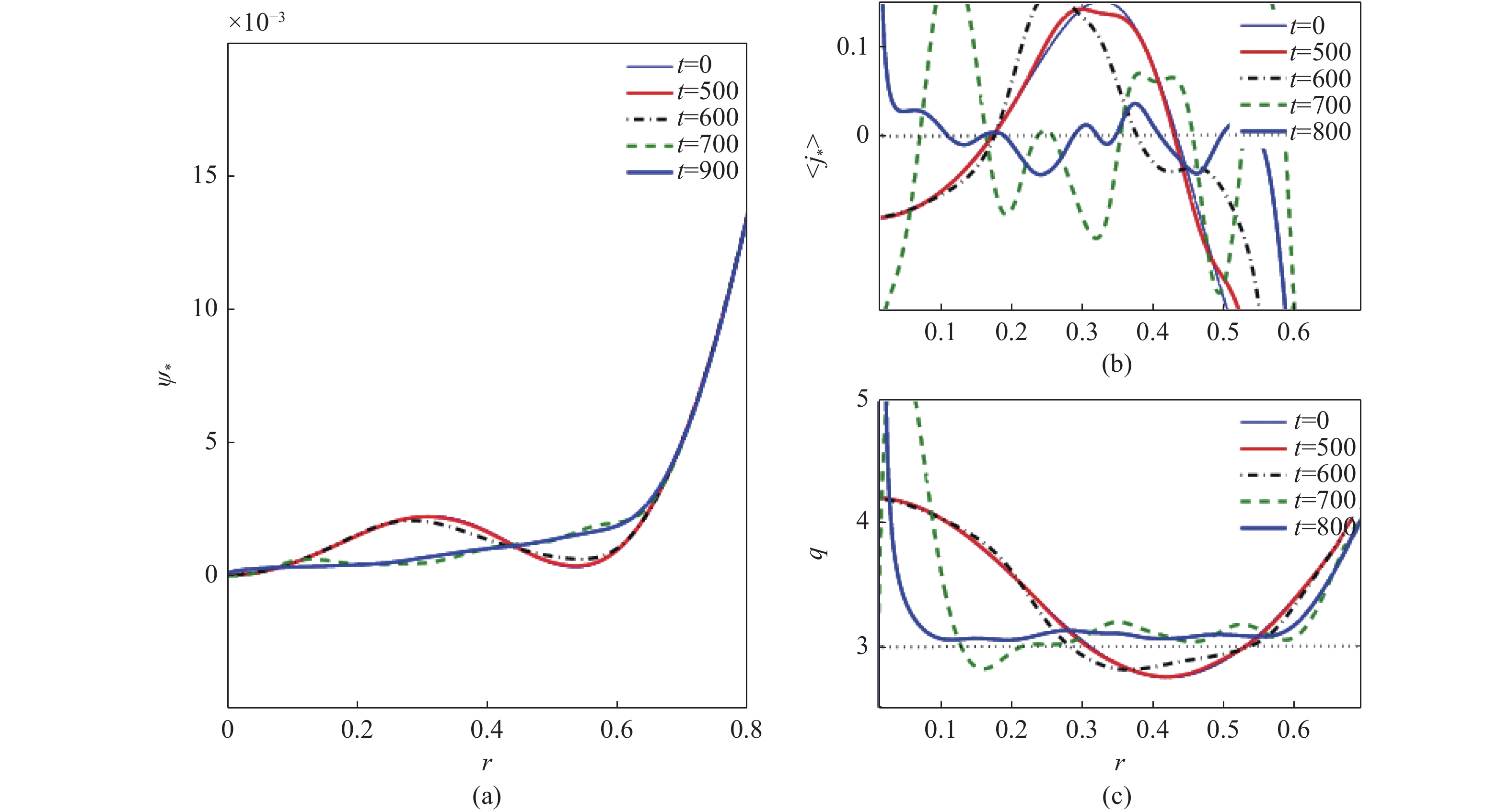
图4从另一角度来看这个发展过程。在两侧磁岛分形线还没开始重合之前的t=500时刻,螺旋通量$ \psi _p^ * $、安全因子剖面$q(r)$以及${j_*}$基本无变化。在t=600时刻,他们的分形线已经重合,磁面拓扑结构刚开始发生变化,$ \psi _p^ * $等也有了比较小的变化。在t=700时刻,内外磁岛已经完成了径向位置的交换,磁面拓扑结构发生大的变化,如图4(c)所示,${q_s} = 3$的有理面位置向等离子体中心大幅移动且两个有理面的距离变得很小,跟Kadomtsev等[21]人的有关螺旋通量的理论相符。所以在旧磁岛湮灭的过程中,在这新的有理面附近会产生新的磁岛。随着系统的进一步发展,螺旋通量被抚平,安全因子剖面被抬高,直至t=900的时刻,可以看到,$q(r)$已经没有${q_s} = 3$的有理面,磁岛也消失了。
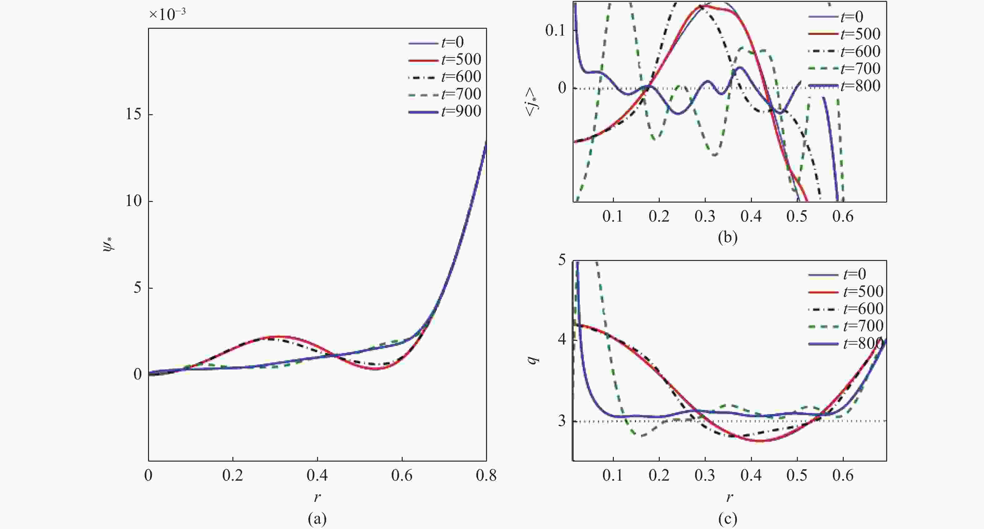
Figure 4. (a) the helical magnetic flux profile, (b) the toroidal current profile and (c) the safety factor profile
-
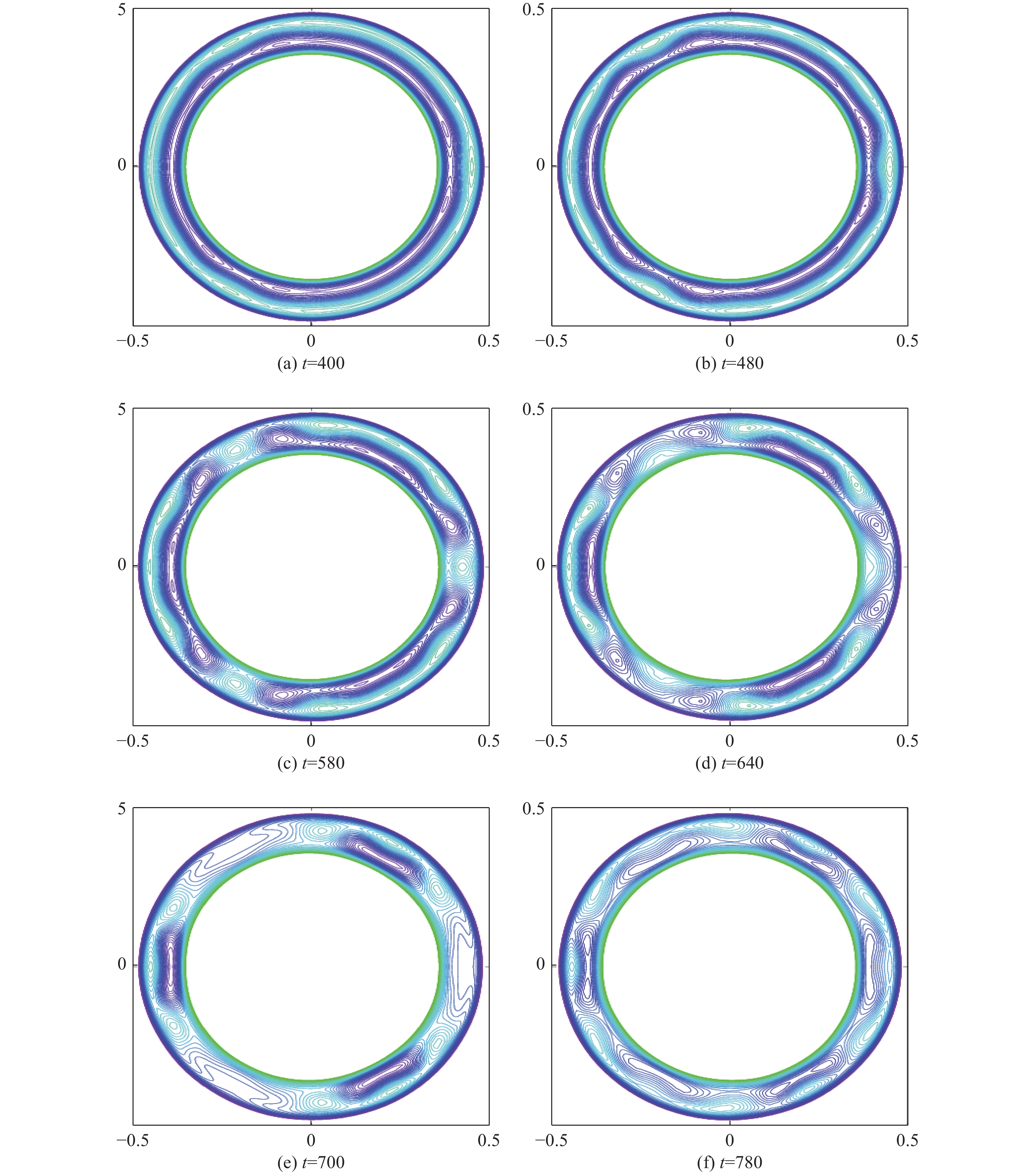
图5显示的是两个有理面距离${D_{12}} = 0.06$、电子磁雷诺数$R = {10^9}$时,系统的磁场位形随时间演化的过程,两个有理面分别在径向r1=0.39和r2=0.45的位置。t=400时刻,在两个有理面上各自产生的磁岛已经发展起来了。到t=480时刻,如图5(b),可以更清晰地看到,内侧有理面产生的是极向模数m=9的磁岛,外侧有理面则产生的是极向模数m=12的磁岛,跟线性理论相符合,两个有理面上的磁岛被中间开放的磁力线所分离。

Figure 5. Contour plot of the helical magnetic flux
因为两个有理面距离很近,所以很快的随着磁岛宽度的增大,中间的开放磁力线被联完了,而内外侧相位错落的磁岛则交叉在一起,如图5(c)。与上一节的分析相同,这部分错落交叉的磁岛会交换径向位置,并分别跟两侧平衡开放磁力线重联,由于磁力线方向相反,重联的结果是让这部分磁岛湮灭,如图5(d)和图5(e)所示。值得注意的是,图5(e)t=700时刻,同时可以看到,m=3的模此时也发展起来了。
因为两个有理面距离很小,同时,在非线性发展早中期,高极向模数的模是支配模式,在磁重联的过程中,只有部分磁岛交换了径向位置,所以对磁面拓扑结构的影响不是很大,没有像两个有理面距离为中等距离时那样激烈的快速变化,如图6(a)中可以看到的,螺旋通量$ \psi _p^ * $变化很微弱。图6(c)中可以看到,t=580时,两个有理面距离没变,但表征磁能的磁剪切s已经变小,对照图5(c),此时两侧部分磁岛联完中间的开放磁力线后,磁岛交叉合并在一起,并开始与两侧开放磁力线重联,磁能损耗。随着磁重联的发展,磁岛的径向位置的交换和湮灭,t=700时,$q(r)$被抬高,两个有理面距离变小,磁剪切s继续变小,直至t=780时刻,$q(r)$剖面离开${q_s}$=3的有理面,磁岛全部湮灭。
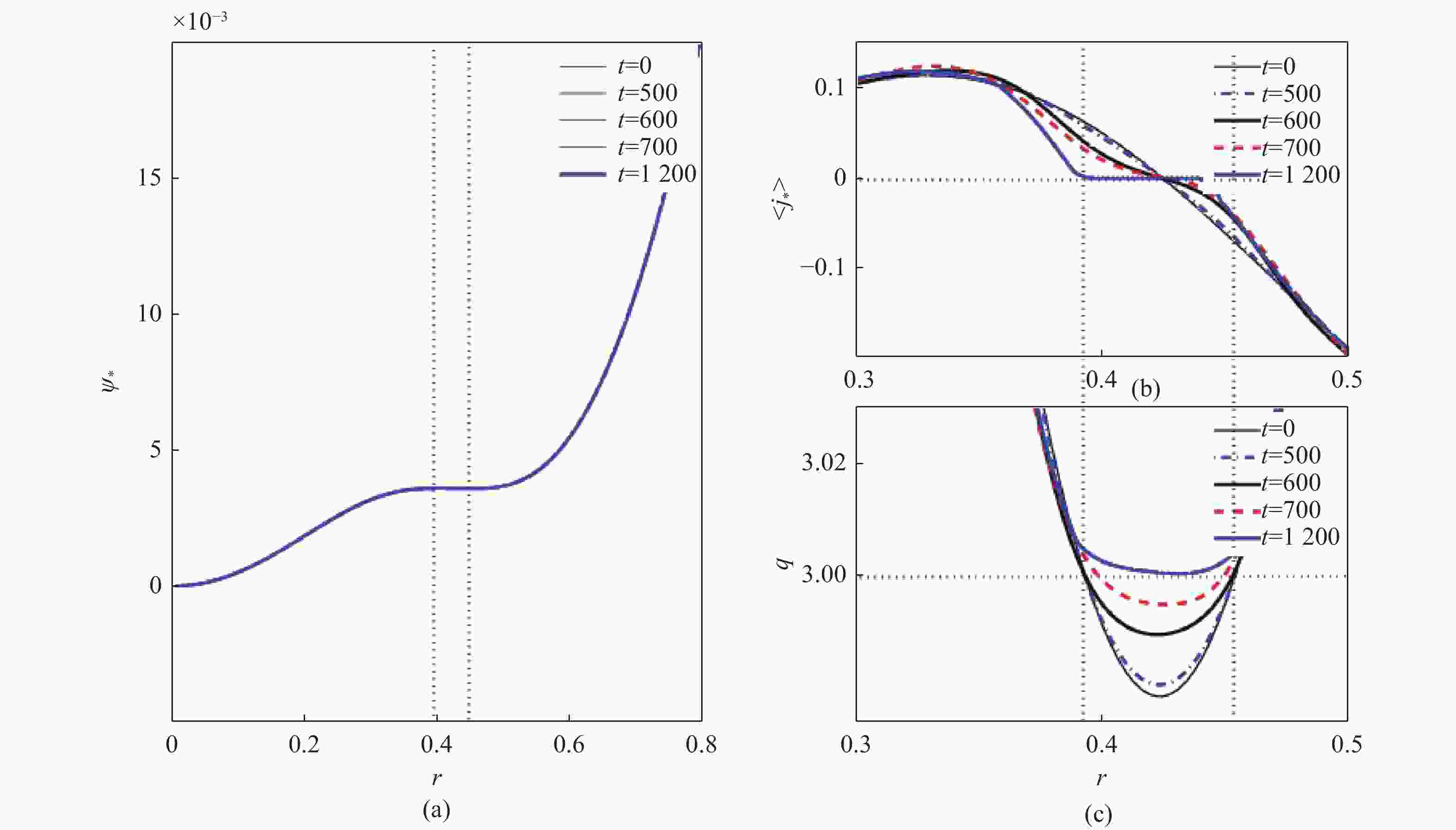
Figure 6. (a) the helical magnetic flux profile, (b) the toroidal current profile and (c) the safety factor profile
-
下面通过对个别的傅里叶展开的模式进行分析,探讨非线性发展的驱动问题。下面讨论要用到的扰动磁能$E_{m,n}^{{\mathrm{mag}}}$、动能$E_{m,n}^{{\mathrm{kin}}}$和非线性增长率表示如下:
$$ E_{m,n}^{{\mathrm{mag}}} = |\nabla {\tilde \psi _{m,n}}{|^2}\text{,}E_{m,n}^{{\mathrm{kin}}} = |\nabla {\tilde \phi _{m,n}}{|^2}\text{,} $$ (14) $$ \gamma _{m,n}^{{\mathrm{mag}}}(t) = \frac{{dE_{m,n}^{{\mathrm{mag}}}}}{{2dt}}\text{,}\gamma _{m,n}^{{\mathrm{kin}}}(t) = \frac{{dE_{m,n}^{{\mathrm{kin}}}}}{{2dt}}\text{,} $$ (15) 从3.2节的分析看,在磁场快速重联过程中,磁力线会高度弯曲,磁场中粒子因而受到比较强的加速,因此此阶段的一个特征就是动能显著的变化。所以下面的分析会以此为判断是否存在快速的磁重联。
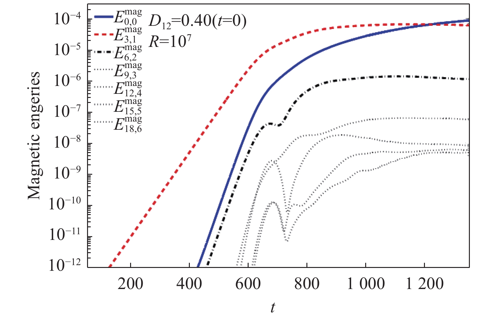
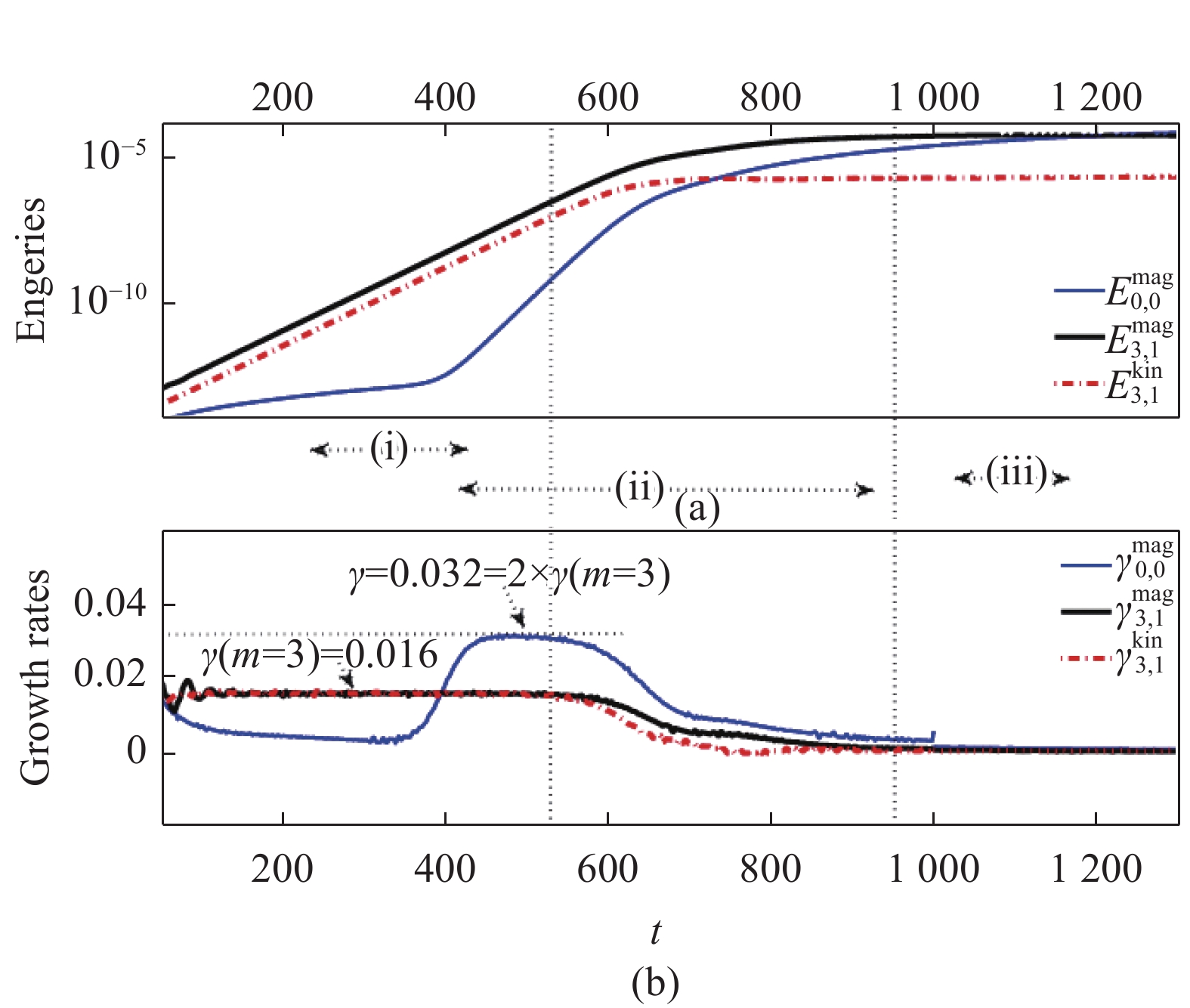
图7显示的是两个有理面初始距离为0.40的扰动磁能随时间的演化,可以看到,在整个非线性发展阶段,m/n=3/1的模磁能一直处于支配模式,跟前面的线性结果相符。因此把3/1模的磁能和动能,0/0的磁能和对应的增长率做单独的分析。如图8所示,可以给这种情况的双撕裂模非线性发展划分大致3个阶段:
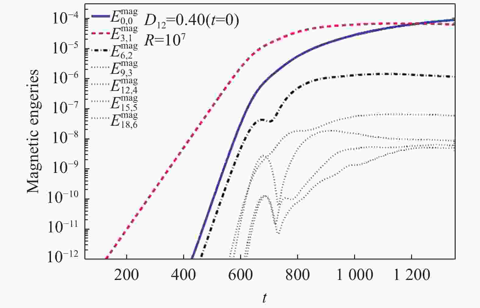
Figure 7. The perturbed magnetic energy as function of time
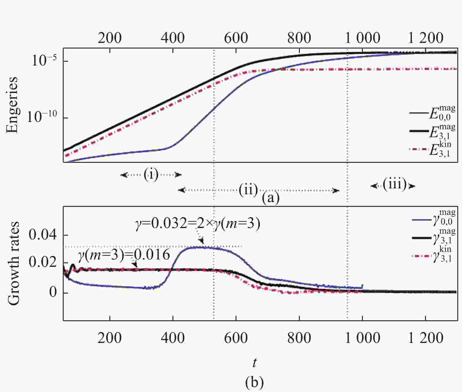
Figure 8. (a) the perturbed magnetic energy and the kinetic energy as functions of time, (b) the corresponding growth rates as functions of time
1) 线性阶段,此阶段逐渐形成3/1的双撕裂模,并且以0.016增长率线性增长,跟用特征值解法得到的线性增长率一致。
2) 非线性驱动阶段,当3/1模增长到一定阶段,两个有理面上发展最快的模式,亦即3/1模开始非线性耦合,并且驱动其他模式发展。非线性驱动的大小可以方便的从m=0的模的增长率推出。需要说明的是,m=0的模是平衡模而不是不稳定模,它的发展是非线性驱动的结果。式(16)给出了增长率分别为${\gamma _a}$和${\gamma _b}$的两个模耦合驱动典型的表达:
$$ \begin{gathered} {{\psi '}_a}(r)\sin ({m_a}{\vartheta _*}){e^{{\gamma _a}t}} \times {\phi _b}(r)\sin ({m_b}{\vartheta _*}){e^{{\gamma _b}t}} = \\ ({{\psi '}_a}{\phi _b}/2)[\cos ({m^ - }{\vartheta _*}) - \cos ({m^ + }{\vartheta _*})]{e^{({\gamma _a} + {\gamma _b})t}} \\ \end{gathered} $$ (16) 这里,${m_a}$和${m_b}$为两个驱动的模模数,他们的线性增长率分别为${\gamma _a}$和${\gamma _b}$,${m^ \pm } = {m_a} \pm {m_b}$分别是受驱动的两个模模数。这式中明显可以得到驱动增长率:
$$ {\gamma _{{\mathrm{drive}}}}({m^ \pm }) = {\gamma _a} + {\gamma _b} $$ (17) 在本例中,驱动的两个模数为${m_a} = {m_b} = 3$,而受驱动的两个模数则为${m^ - } = 0$和${m^ + } = 6$,如图7所示,在图8中也可以看到,$\gamma (m = 0) = 0.032 = 2 \times \gamma (m = 3)$,与式(17)相符。由于两个有理面的距离较大,因此耦合很弱,因此不稳定模m=3的模一直处于支配状态直至磁岛饱和。
3) 维持磁岛饱和状态的稳定状态,在比较长的时间尺度将不会有太大变化。
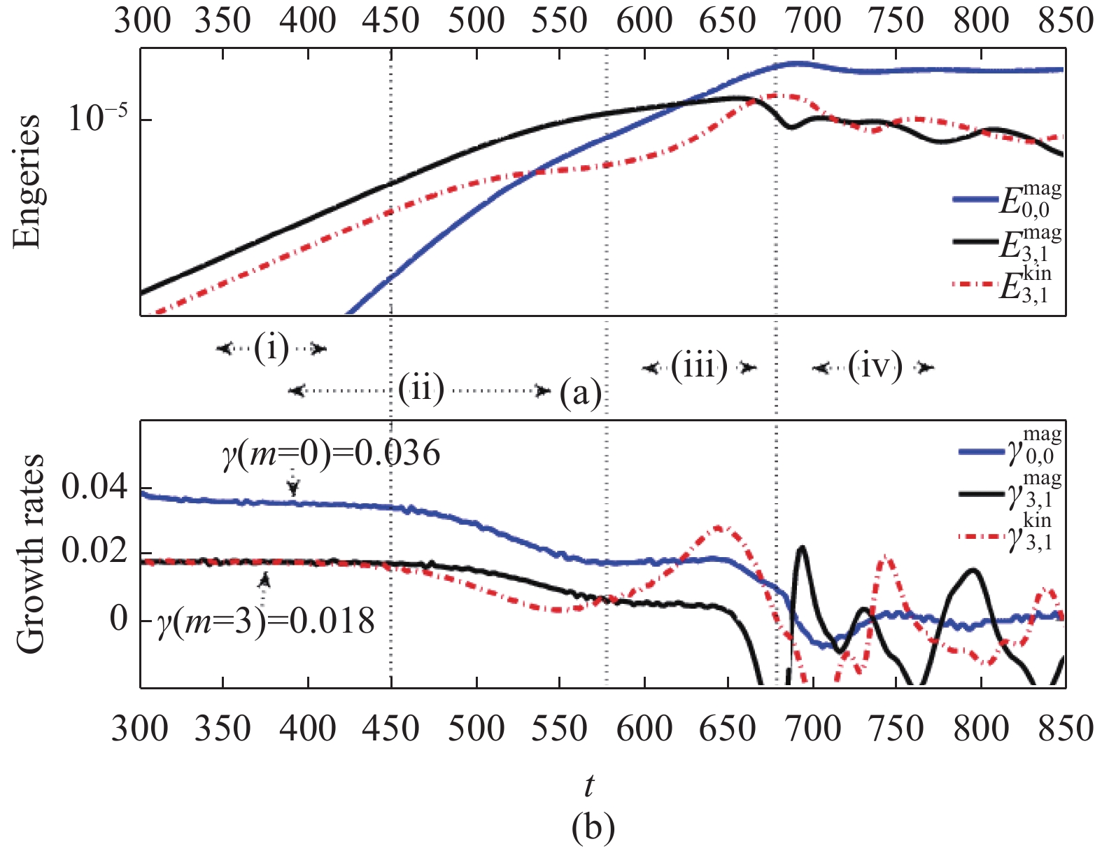
图9则给出了两个有理面距离为中等距离0.22的情况。因为同样是m=3的模是支配模式,这里不再单独给出扰动磁能随时间的演变图。从图中可以看到,大概可以分为4个阶段,一、二阶段同前,有:1) 线性发展阶段,此阶段m=3的双撕裂模以0.018增长率线性增长,跟用特征值解法得到的线性增长率一致。
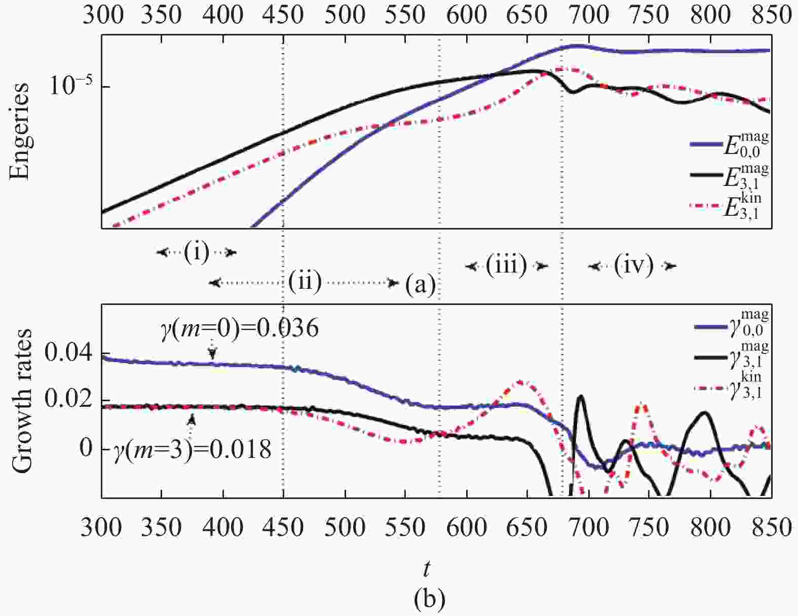
Figure 9. (a) the perturbed magnetic energy and the kinetic energy as functions of time, (b) the corresponding growth rates as functions of time
2) 非线性驱动阶段,此阶段m=0的模的增长率为0.036,2倍于m=3模的增长率,跟理论结果是一致的。
3) 快速发展阶段。从前面对磁岛和磁力线随时间演变的分析可知,两个有理面距离为中等距离的时候,非线性发展到一定阶段,在磁岛饱和之前,两个有理面上的磁岛就已经把中间的开放磁力线联完,系统继续发展,他们交换了径向位置,分别与两侧的平衡开放磁力线重联,结果是磁岛的湮灭。这是一个快速的过程,磁场的第二次重联,即磁岛交换径向位置后磁岛的闭合磁力线与反向的平衡开放磁力线之间的湮灭重联,远远快于磁岛增大的正向重联。
4) 衰减阶段。因为磁岛径向位置的交换及磁岛的湮灭,磁场拓扑结构很大的改变,因此快速发展过后,就进入衰减阶段。此阶段因为磁场拓扑结构的改变,有理面位置也发生改变,从图4知道,有理面向等离子体中心靠拢,且距离变小。在新的有理面会产生新的磁岛,重复重联湮灭的过程,直至q剖面离开${q_s}$=3的有理面,磁岛完全消失。
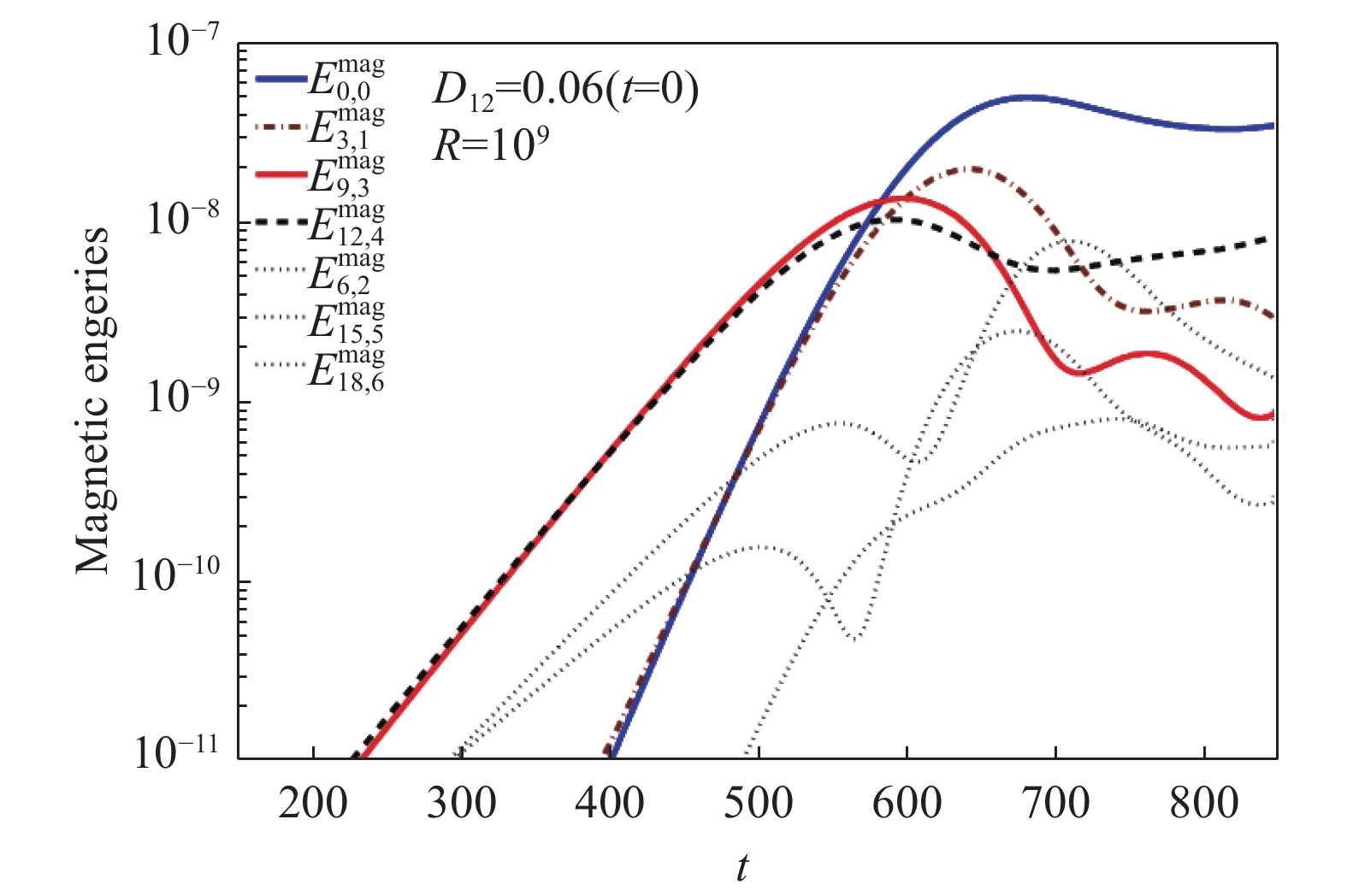
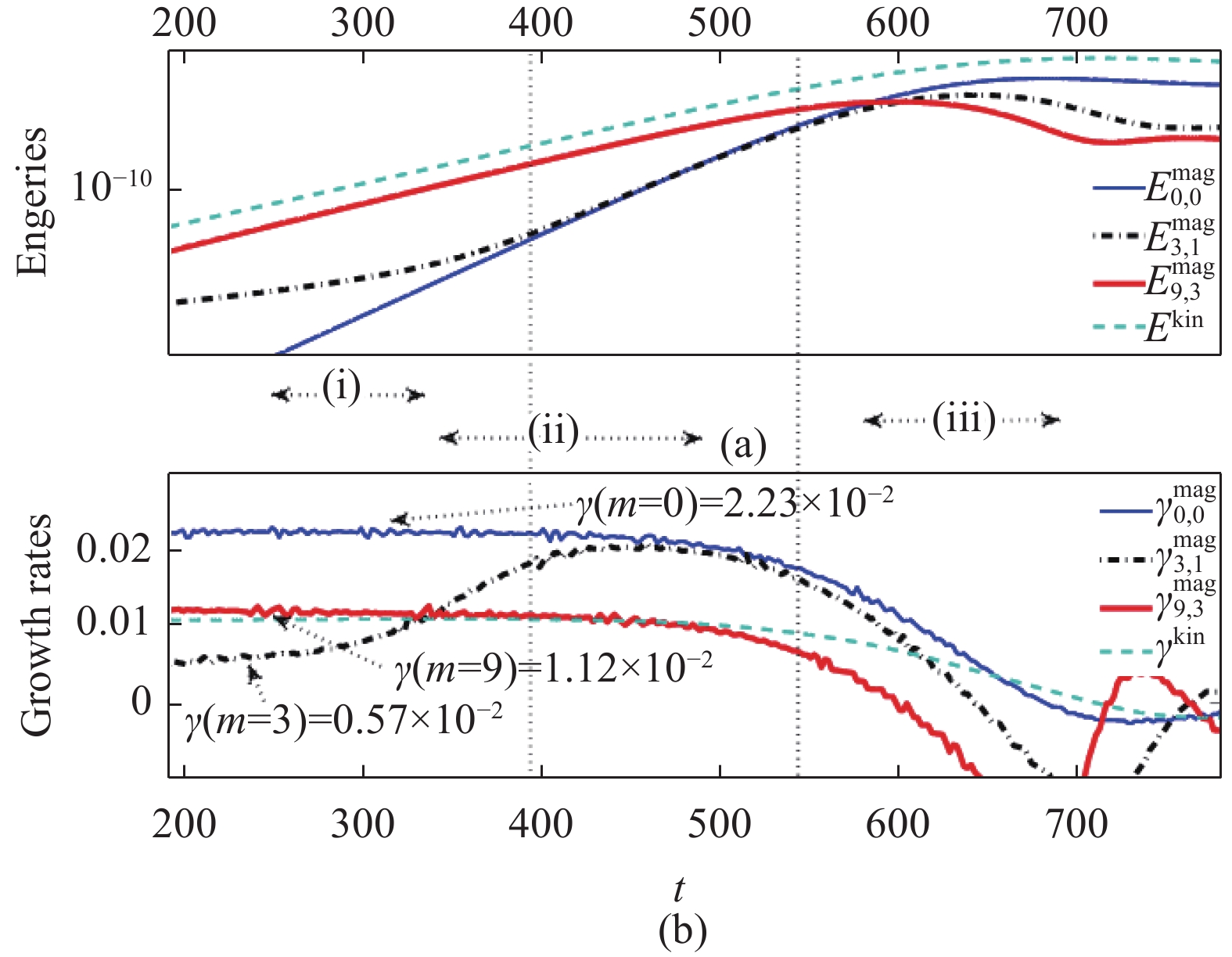
图10显示的是两个有理面初始距离为0.06的扰动磁能随时间的演化,可以看到,在整个非线性发展中前期,m/n=9/3和12/4的模磁能处于支配模式,跟前面的线性结果相符,而3/1模和0/0模受他们耦合的驱动。因此把9/3、3/1、0/0模的磁能及其增长率放在图11比较研究,同时给出总动能及其增长率,因为在这里,高极向模发展起来了,不能再单独以3/1模或9/3模的动能作判断。从图11中可以看到,大致可以分为4个阶段。
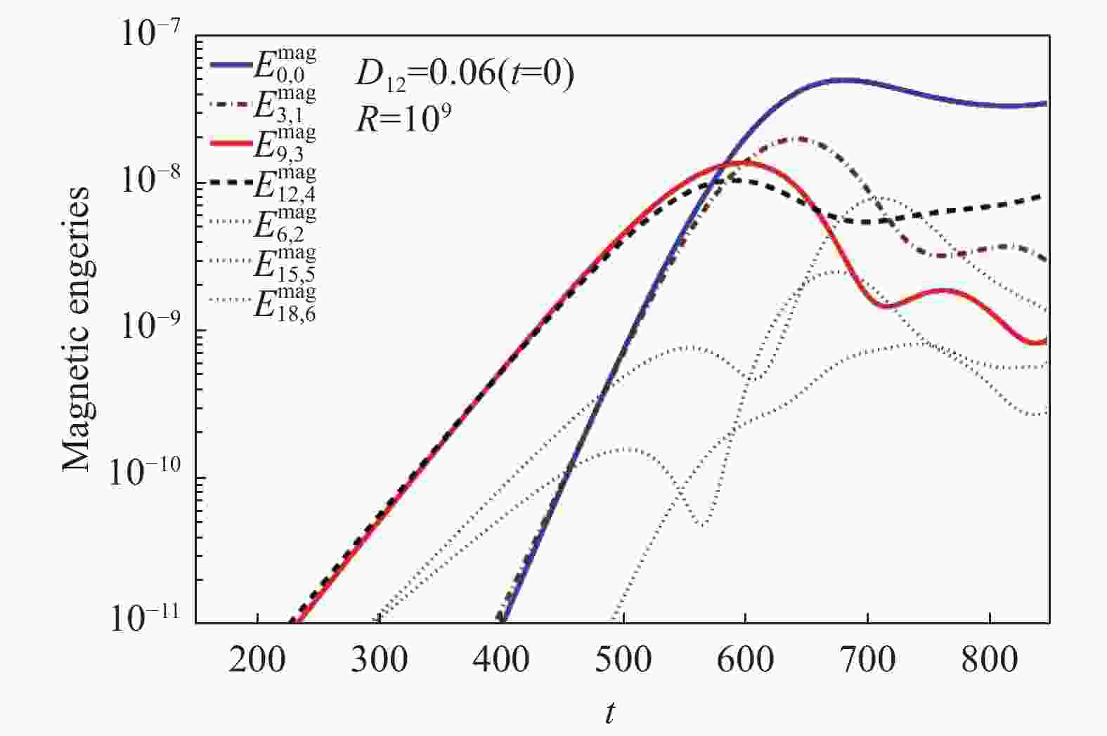
Figure 10. The time evolution of perturbed magnetic energy
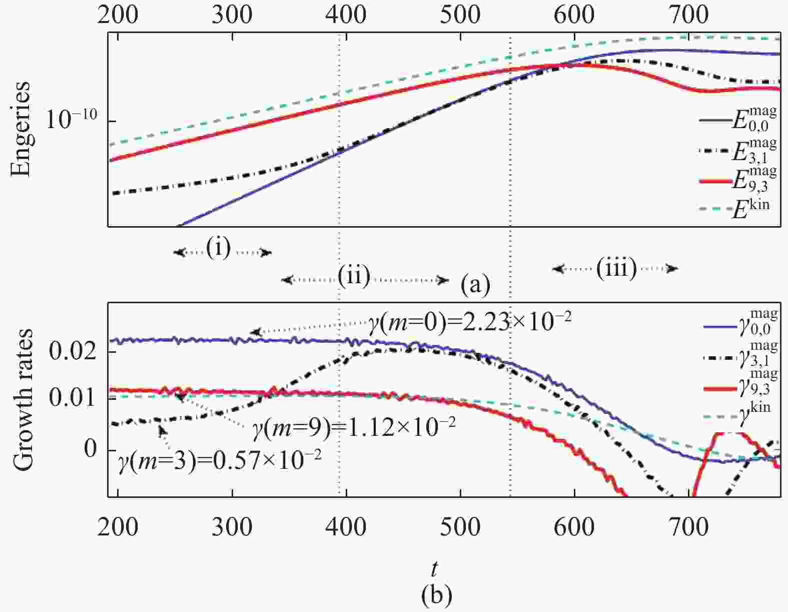
Figure 11. (a) the perturbed magnetic energy and the kinetic energy as functions of time, (b) the corresponding growth rates as functions of time
1) 线性发展阶段。此阶段m=3的模以0.57×10⁻²的增长率线性增长,而m=9的模以1.12×10⁻²的增长率线性增长,跟用特征值解法得到的线性增长率一致。
2) 非线性驱动阶段。此阶段两个有理面上的磁岛,分别以发展最快的m=9和m=12两种模耦合,并驱动m=0和m=3的模,此时m=0的模增长率是m=9和m=12两个模的增长率之和:
$$\begin{split} &\gamma (m = 0) = 2.23 \times {10^{ - 2}} = 1.12 \times {10^{ - 2}} + 1.11 \times {10^{ - 2}} =\\& \gamma (m = 9) + \gamma (m = 12) \end{split}$$ (18) 且在t=400时刻左右,$\gamma (m = 3) \approx \gamma (m = 0)$,跟理论结果是相符的。
3) 二次磁重联及4)衰减阶段。从动能演化曲线可以看到,在非线性驱动阶段后,并没有出现动能的快速变化。从3.3节的分析可知,由于线性驱动是高极向模之间的耦合,没有3/1之间的耦合那种磁岛间相位完全互补的可能,因此在二次磁重联中,两个有理面上的磁岛只有部分发生了径向位置的交换,同时因为两个有理面距离很小,所以对磁场拓扑结构影响相对较小。因此没有出现两个有理面中等距离时的那种快速发展。${q_s} = 3$有理面上的双撕裂模在磁场重联中衰减,经过相对较长的时间,${q_s} = 3$有理面消失(如图6),模式亦消失。
-
用圆柱位形的磁流体动力学,对由反常电子粘滞性引起的双撕裂模的非线性发展做了数值研究。研究表明,两个有理面的间距的大小,对双撕裂模非线性发展有很大影响。
1) 当两个有理面的间距比较大的时候,由于非线性耦合的驱动较弱,双撕裂模经过较长时间的线性发展,最后在两个有理面上两个磁岛各自达到饱和状态并形成稳态。
2) 当两个有理面距离为中等距离的时候,非线性发展可以分为4个阶段:第一个阶段是线性阶段,低极向模为支配模式,并且其模式增长率为线性增长率;第二阶段是非线性驱动的阶段,两个有理面上的低模的耦合驱动平衡模的发展;第一二阶段同两个有理面间距大的时候是一样的。由于两个有理面距离相对较近,两个有理面上的磁岛增长未达饱和之前,他们就交换了径向位置,并分别与两侧的开放磁力线进行快速的反向重联,即磁岛的湮灭,这就是第三阶段快速磁重联阶段;由于快速磁重联对磁场拓扑结构的破坏,模式最后进入衰减阶段。
3) 当两个有理面距离很小的时候,高极向模数的模式会发展起来并成为支配模式。各种极向模数的模式会经过短暂的第一阶段的线性增长,然后发展起来的高极向模数的模式会耦合驱动平衡模和低极向模数进入非线性驱动的第二阶段。由于有理面间距很小,两个有理面之间的磁岛很快会发生二次磁重联,但由于高极向模式的相位特点使得二次重联时只有部分磁岛发生了径向位置的交换,因此并没有快速重联过程,双撕裂模模式在较缓慢的磁重联中衰减直至消失。
Nonlinear Evolution of Double Tearing Mode Mediated by Parallel Electron Viscosity
- Received Date: 2024-01-12
- Rev Recd Date: 2024-01-22
- Available Online: 2024-01-25
-
Key words:
- double tearing mode /
- parallel electron viscosity /
- plasma simulation /
- nonlinear evolution /
- magnetic reconnection
Abstract:
| Citation: | HE Zhixiong, DONG Jiaqi, JIANG Haibin. Nonlinear evolution of double tearing mode mediated by parallel electron viscosity [J]. Southern energy construction, 2024, 11(3): 1-11. DOI:

|

 DownLoad: