• Peer Review
  • Non-profit
  • Global Open Access
  • Green Channel for Rising Stars
Turn off MathJax
Article Contents

SU Hang, LI Hua, SONG Zhiquan, et al. Conceptual design of novel fusion power supply with energy storage [J]. Southern energy construction, 2024, 11(3): 1-9. DOI: 10.16516/j.ceec.2024-029 doi:  10.16516/j.ceec.2024-029
Citation: SU Hang, LI Hua, SONG Zhiquan, et al. Conceptual design of novel fusion power supply with energy storage [J]. Southern energy construction, 2024, 11(3): 1-9. DOI: 10.16516/j.ceec.2024-029 doi:  10.16516/j.ceec.2024-029

Conceptual Design of Novel Fusion Power Supply with Energy Storage

doi: 10.16516/j.ceec.2024-029
  • Received Date: 2024-01-26
  • Accepted Date: 2024-03-18
  • Rev Recd Date: 2024-03-14
  •   Introduction  In recent years, as the installed capacity of the fusion device has been increasing, the power supply system of the device requires high-amplitude and long-pulse power output, which causes a strong power impact on the grid, and even power supply disconnection in severe cases to pose a serious threat to the safety of the fusion device. Additionally, the high-amplitude pulses also result in a lot of redundancy in the power supply system design.   Method  To solve these problems, this paper proposed a novel fusion power supply topology with energy storage, that is, the power supply system was designed with energy storage to mitigate the impact of pulse power on the grid. During the operation of the power supply, the grid provided steady-state power while the energy storage device delivered pulse power, effectively reducing the cost of the power supply.   Result  According to the experience in industrial power supply and distribution, this paper presents the calculation formulas for the selection of key components in different topologies and conducts a cost analysis and comparison for different power supply topologies based on simulation data.   Conclusion  The experimental results show that the new power supply topology not only reduces the power impact on the grid and improves the energy utilization of the power supply system, but also reduces transformer capacity, thus it is cost-efficient.
  • [1] FU P, GAO G, SONG Z H Q, et al. Preliminary design of the poloidal field AC/DC converter system for the ITER coil power supply [J]. Fusion science and technology, 2013, 64(4): 741-747. DOI:  10.13182/FST13-A24094.
    [2] KÄSEMANN C P, HUART M, LIESHOUT L V, et al. Extension of the pulsed power supply network of ASDEX upgrade by a set of compact modular generators [J]. Fusion engineering and design, 2011, 86(6/8): 1523-1526. DOI:  10.1016/j.fusengdes.2011.03.026.
    [3] SHIMADA K, BAULAIGUE O, CARA P, et al. Design study of an AC power supply system in JT-60SA [J]. Fusion engineering and design, 2011, 86(6/8): 1427-1431. DOI:  10.1016/j.fusengdes.2011.02.097.
    [4] SONG I, EOM D, AHN H. The operation results and study of KSTAR pulsed electric power network for superconducting magnet power supply [J]. Fusion engineering and design, 2019, 143: 164-170. DOI:  10.1016/j.fusengdes.2019.03.132.
    [5] BERTOLINI E, MONDINO P L, NOLL P. The JET magnet power supplies and plasma control systems [J]. Fusion technology, 1987, 11(1): 71-119. DOI:  10.13182/FST87-A25001.
    [6] 胡星光, 宋执权, 高格, 李华, 傅鹏, 李航. ITER聚变装置及其电源系统 [J]. 南方能源建设, 2022, 9(2): 19-25. DOI:  10.16516/j.gedi.issn2095-8676.2022.02.002.

    HU Xingguang, SONG Zhiquan, GAO Ge, LI Hua, FU Peng, LI Hang. ITER Fusion Device and Its Power Supply System [J]. SOUTHERN ENERGY CONSTRUCTION, 2022, 9(2): 19-25. DOI:  10.16516/j.gedi.issn2095-8676.2022.02.002.
    [7] NEUMEYER C, BENFATTO I, HOURTOULE J, et al. ITER power supply innovations and advances [C]//2013 IEEE 25th symposium on fusion engineering (SOFE), San Francisco, CA, USA, June 10-14, 2013. San Francisco: IEEE, 2013: 1-8. DOI:  10.1109/SOFE.2013.6635287.
    [8] HOURTOULE J, NEUMEYER C, SUH I, et al. ITER electrical distribution system [C]//2013 IEEE 25th Symposium on fusion engineering (SOFE), San Francisco, CA, USA, June 10-14, 2013. San Francisco: IEEE, 2013: 1-5. DOI:  10.1109/SOFE.2013.6635314.
    [9] GOFF J, GASCON J, MANKANI A, et al. The ITER magnet power supplies and control system [C]//2010 International conference on electrical machines and systems, Incheon, Korea (South), October 10-13, 2010. Incheon: IEEE, 2010: 346-351.
    [10] TIAN Y X, WU Y N, LU J, et al. Research on a novel hybrid power supply scheme with energy storage technology for Tokamak [J]. International journal of energy research, 2023, 2023: 2163067. DOI:  10.1155/2023/2163067.
    [11] 李磊. ITER电源系统冲击功率补偿策略研究 [D]. 合肥: 安徽大学, 2021.

    LI L. Research on impact power compensation strategy of ITER power supply system [D]. Hefei: Anhui university, 2021.
    [12] PENG J F, XUAN W H, WANG H B, et al. Study on matching a 300 MVA motor generator with an Ohmic heating power supply in HL-2M [J]. Plasma science and technology, 2013, 15(3): 300-302. DOI:  10.1088/1009-0630/15/3/22.
    [13] KÄSEMANN C P, GROIS E, STOBBE F, et al. Pulsed power supply system of the ASDEX upgrade Tokamak research facility [C]//2015 IEEE 15th International Conference on Environment and Electrical Engineering, Rome, Italy, June 10-13, 2015. Rome: IEEE, 2015: 237-242.
    [14] AHN H S, LEE D K, CHOI J H, et al. Operation of KSTAR PF superconducting magnet power supplies under MG power system [J]. IEEE transactions on applied superconductivity, 2016, 26(4): 0601204. DOI:  10.1109/TASC.2016.2522558.
    [15] SHAO C, WEI B, LIU W F, et al. Multi-dimensional value evaluation of energy storage systems in new power system based on multi-criteria decision-making [J]. Processes, 2023, 11(5): 1565. DOI:  10.3390/pr11051565.
    [16] 孙瑜歌, 丁涛, 黄雨涵, 等. 高比例新能源电力市场不同发展阶段划分及形态结构演进 [J]. 高电压技术, 2023, 49(7): 2725-2743. DOI: 10.13336/j.1003-6520.hve.2023 0122.

    SUN Y G, DING T, HUANG Y H, et al. Development stage division and morphological evolution of power market with high proportion of renewable energy [J]. High voltage engineering, 2023, 49(7): 2725-2743. DOI: 10.13336/j.1003-6520.hve.2023 0122.
    [17] 国家能源局. 国家能源局公布2021年能源成绩单 [EB/OL]. (2021-12-24) [2022-10-25]. http://www.nea.gov.cn/2021-12/24/c_1310391383.htm.

    National Energy Administration. The National Energy Administration announces the 2021 energy transcript [EB/OL]. (2021-12-24) [2022-10-25]. http://www.nea.gov.cn/2021-12/24/c_1310391383.htm.
    [18] 梁展鹏, 向魁, 李华, 朱光涛. CFETR聚变发电厂的储能技术适用性分析 [J]. 南方能源建设, 2022, 9(2): 53-62. DOI:  10.16516/j.gedi.issn2095-8676.2022.02.007.

    LIANG Zhanpeng, XIANG Kui, LI Hua, ZHU Guangtao. Applicability Analysis of Energy Storage Techniques for CFETR Fusion Power Plant [J]. SOUTHERN ENERGY CONSTRUCTION, 2022, 9(2): 53-62. DOI:  10.16516/j.gedi.issn2095-8676.2022.02.007.
    [19] 常晓勇. 功率型储能系统在直流微电网运行控制中的关键技术研究 [D]. 天津: 天津大学, 2017.

    CHANG X Y. Research on key technologies of power-type energy storage systems in DC micro-grid operation and control [D]. Tianjin: Tianjin University, 2017.
    [20] 姜海洋, 杜尔顺, 马佳豪, 等. 考虑长周期供需不平衡风险的新型电力系统规划方法 [J]. 中国电机工程学报, 2024: 1-14. DOI:  10.13334/j.0258-8013.pcsee.230440.

    JIANG H Y, DU E S, MA J H, et al. Power system optimal planning method considering long-term imbalance risk [J/OL]. Proceedings of the CSEE, 2024: 1-14. DOI:  10.13334/j.0258-8013.pcsee.230440.
    [21] 胡星光, 宋执权, 高格, 等. ITER聚变装置及其电源系统 [J]. 南方能源建设, 2022, 9(2): 19-25. DOI:  10.16516/j.gedi.issn2095-8676.2022.02.002.

    HU X G, SONG Z Q, GAO G, et al. ITER fusion device and its power supply system [J]. Southern energy construction, 2022, 9(2): 19-25. DOI:  10.16516/j.gedi.issn2095-8676.2022.02.002.
    [22] COLETTI A, BAULAIGUE O, CARA P, et al. JT-60SA power supply system [J]. Fusion engineering and design, 2011, 86(6/8): 1373-1376. DOI:  10.1016/j.fusengdes.2011.02.042.
    [23] NOVELLO L, BAULAIGUE O, COLETTI A, et al. Overview of the new magnet power supply systems of JT-60SA procured by EU [J]. Fusion engineering and design, 2015, 98/99: 1122-1126. DOI:  10.1016/j.fusengdes.2015.06.014.
    [24] CHOI J H, YANG H L, AHN H S, et al. Overview of superconducting magnet power supply system for the KSTAR 1st plasma experiment [J]. Nuclear engineering and technology, 2008, 40(6): 459-466. DOI:  10.5516/NET.2008.40.6.459.
    [25] MAGNANIMO A, TESCHKE M, GRIEPENTROG G. Full-bridge submodule development of an MMC-Like topology for ASDEX upgrade toroidal field coils power supply [J]. IEEE transactions on plasma science, 2022, 50(7): 2178-2184. DOI:  10.1109/TPS.2022.3179624.
    [26] ANEKE M, WANG M H. Energy storage technologies and real life applications-a state of the art review [J]. Applied energy, 2016, 179: 350-377. DOI:  10.1016/j.apenergy.2016.06.097.
    [27] OUDALOV A, CHARTOUNI D, OHLER C. Optimizing a battery energy storage system for primary frequency control [J]. IEEE transactions on power systems, 2007, 22(3): 1259-1266. DOI:  10.1109/TPWRS.2007.901459.
    [28] VERGARA C R. Parametric interface for battery energy storage systems providing ancillary services [C]//2012 3rd IEEE PES Innovative Smart Grid Technologies Europe (ISGT Europe), Berlin, Germany, October 14-17, 2012. Berlin: IEEE, 2012: 1-7. DOI:  10.1109/ISGTEurope.2012.6465765.
    [29] KOEHLER U, KRUGER F J, KUEMPERS J, et al. High performance nickel-metal hydride and lithium-ion batteries [C]//IECEC-97 Proceedings of the Thirty-Second Intersociety Energy Conversion Engineering Conference (Cat. No. 97CH6203), Honolulu, HI, USA, July 27, 1997-August 01, 1997. Honolulu: IEEE, 1997: 93-98. DOI:  10.1109/IECEC.1997.659166.
    [30] LUKIC S M, CAO J, BANSAL R C, et al. Energy storage systems for automotive applications [J]. IEEE transactions on industrial electronics, 2008, 55(6): 2258-2267. DOI:  10.1109/TIE.2008.918390.
    [31] LUO X, WANG J H, DOONER M, et al. Overview of current development in electrical energy storage technologies and the application potential in power system operation [J]. Applied energy, 2015, 137: 511-536. DOI:  10.1016/j.apenergy.2014.09.081.
    [32] NIKOLAIDIS P, POULLIKKAS A. Cost metrics of electrical energy storage technologies in potential power system operations [J]. Sustainable energy technologies and assessments, 2018, 25: 43-59. DOI:  10.1016/j.seta.2017.12.001.
  • 通讯作者: 陈斌, bchen63@163.com
    • 1. 

      沈阳化工大学材料科学与工程学院 沈阳 110142

    1. 本站搜索
    2. 百度学术搜索
    3. 万方数据库搜索
    4. CNKI搜索

Figures(5)  / Tables(6)

Article Metrics

Article views(36) PDF downloads(9) Cited by()

Related

Conceptual Design of Novel Fusion Power Supply with Energy Storage

doi: 10.16516/j.ceec.2024-029

Abstract:   Introduction  In recent years, as the installed capacity of the fusion device has been increasing, the power supply system of the device requires high-amplitude and long-pulse power output, which causes a strong power impact on the grid, and even power supply disconnection in severe cases to pose a serious threat to the safety of the fusion device. Additionally, the high-amplitude pulses also result in a lot of redundancy in the power supply system design.   Method  To solve these problems, this paper proposed a novel fusion power supply topology with energy storage, that is, the power supply system was designed with energy storage to mitigate the impact of pulse power on the grid. During the operation of the power supply, the grid provided steady-state power while the energy storage device delivered pulse power, effectively reducing the cost of the power supply.   Result  According to the experience in industrial power supply and distribution, this paper presents the calculation formulas for the selection of key components in different topologies and conducts a cost analysis and comparison for different power supply topologies based on simulation data.   Conclusion  The experimental results show that the new power supply topology not only reduces the power impact on the grid and improves the energy utilization of the power supply system, but also reduces transformer capacity, thus it is cost-efficient.

SU Hang, LI Hua, SONG Zhiquan, et al. Conceptual design of novel fusion power supply with energy storage [J]. Southern energy construction, 2024, 11(3): 1-9. DOI: 10.16516/j.ceec.2024-029 doi:  10.16516/j.ceec.2024-029
Citation: SU Hang, LI Hua, SONG Zhiquan, et al. Conceptual design of novel fusion power supply with energy storage [J]. Southern energy construction, 2024, 11(3): 1-9. DOI: 10.16516/j.ceec.2024-029 doi:  10.16516/j.ceec.2024-029
    • 托卡马克装置是最有希望实现聚变发电的技术。近年来,各个国家都在对这项技术加大投入,托卡马克装置的装机容量也在不断增加,部分大型聚变装置的电源参数见表1[1-5]。为了实现稳定可控的核聚变反应,托卡马克的超导磁体电源需要输出百兆瓦级的脉冲功率,用于产生约束等离子体的强磁场[6]。以国际热核聚变实验堆组织(ITER)为例,它的脉冲功率需要达到毫秒级的响应速度,幅值高达260 MW,每个脉冲周期持续时间长达数百秒[7-8],这对电网造成了极大的功率冲击,在实验的过程中,可能会造成电源脱网、放电中断等意外事故,严重威胁聚变装置运行安全[10]。电源产生的无功功率会导致电网电压的有效值下降,电压波形发生畸变等问题,可以通过无功补偿装置进行补偿,但有功功率较难处理[11],它会导致电网中临近负荷的发电机转子发生震荡,导致电网稳定性下降,严重时甚至会造成电网解体。可见,功率冲击是聚变领域的一个难题。

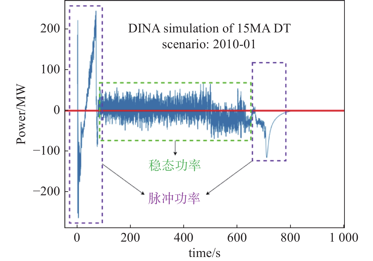
      聚变装置 ITER ASDEX-U JT-60SA KSTAR JET
      电网电压/kV 400 110 275 154 400
      主变压器容量/MVA 900 16 388 100 900
      脉冲发电机容量/MVA 571 615 200 400
      磁体电源容量/MVA 2 243 600 256.2 227.5 939
      辅助加热电源容量/MVA 270 95 128 28 320

      Table 1.  Fusion device power supply parameters[1-5]

      解决这个难题最直接的办法就是增加电网容量,但这种做法的经济性很差。在托卡马克的运行周期里,脉冲功率输出时间占比很小,大多数时间都输出幅值远小于脉冲功率的稳态功率[10],这造成了极大的浪费。图1为ITER电源的功率输出曲线,可以看到脉冲功率的输出时间占比不足整个周期的20%,幅值为稳态功率的数倍。而且,电网的容量受当地经济政策的影响较大,以德国的ASDEX-U为例,所在地的电网容量只有16 MVA,如果想要达到装置运行所需的600 MVA,需要扩容37.5倍,这将带来沉重的经济负担。

      Figure 1.  Total power curve of ITER power supply system

      加装脉冲发电机是常用的措施[12-14],在多个托卡马克中得到了应用。ASDEX-U的电源系统几乎全部使用脉冲发电机供电,可满足短时实验的要求[13]。KSTAR也部署了脉冲发电机作为功率补充[14],避免因功率冲击造成失稳脱网。但是脉冲发电机的发电时间比较短,无法支撑起分钟级的脉冲能量输出,不能匹配当前托卡马克的运行工况。而且脉冲发电机组的运行维护的成本和复杂度较高,综上,脉冲发电机并不是解决该问题的最佳选择。

      近年来,加装储能元件是电网对抗功率波动的重要手段之一[15]。随着技术的发展和政策的支持,越来越多的可再生能源发电厂接入网,截止2021年,在中国的电力系统中,可再生能源发电装机容量接近40%[16]。受自然环境的影响,新能源发电带有强烈的波动性,大量入网让电网的稳定性有所下降。为了改善电能质量,电力公司会部署部分储能装置,大部分为抽水蓄能(约占80%),剩下的部分以锂离子电池为主,用以补充短时功率不平衡,2021年,中国抽水蓄能电站累计装机容量超过3.4 GW,新型储能装机容量达4 GW[17]。储能技术同样也可以用在托卡马克装置上,用于补偿巨大的脉冲功率冲击[18]。储能技术在解决功率冲击这个问题上的优势非常明显,首先,它在电网中得到了广泛的应用,在电力工业界积累了大量的经验[19-20],产业成熟度较高;其次,储能元件可通过电力电子变流器快速精准地输出托卡马克装置所需的功率;最后,部署储能装置可以有效减小变压器容量,会带来一定的经济性。

      当前聚变电源的设计参数为最大脉冲值,但在托卡马克装置的运行周期中,如图1所示,脉冲功率时间只占20%左右,80%的时间里,电源的输出功率远小于脉冲峰值功率,电源系统的容量利用率非常低。在加装储能装置后,脉冲功率由储能装置提供,稳态功率由电网提供,可以有效降低电源系统的参数需求,降低主变压器和整流变压器的容量,减小断路器、母线等元件的成本。
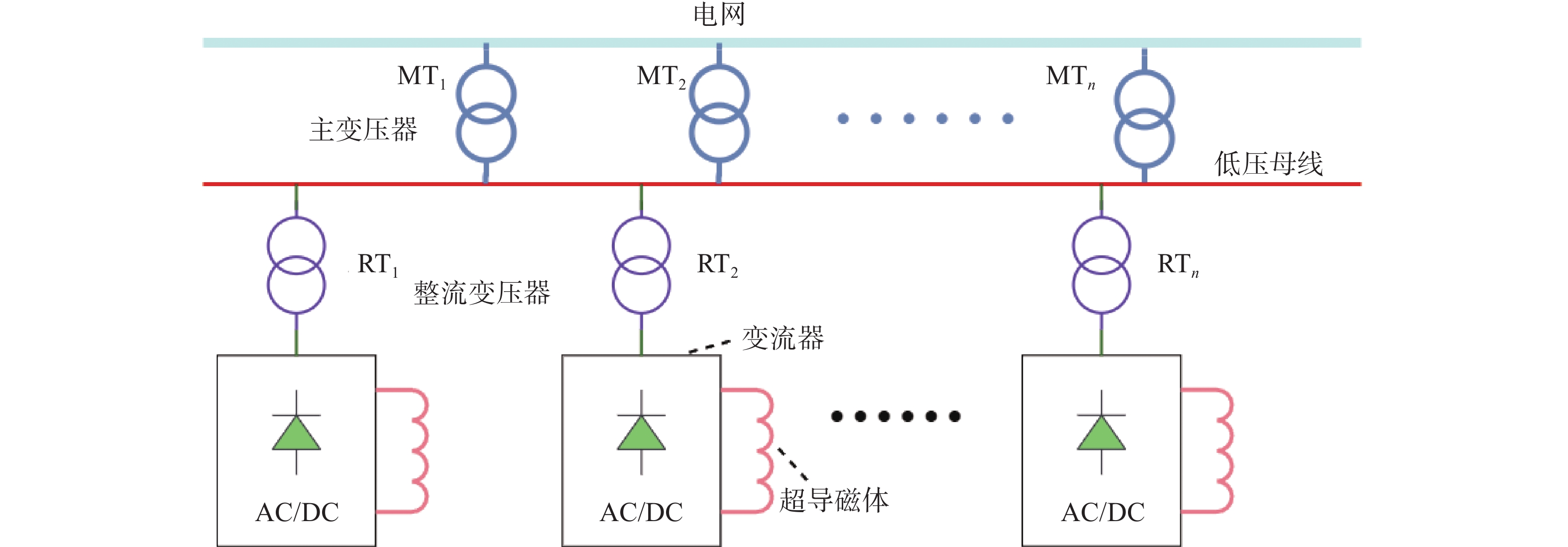
    • 传统的托卡马克电源系统的拓扑结构[21-23]图2所示,电源通过1台或多台主变压器接入电网,每个超导磁体都需要一个AC/DC变流器,每台变流器的整流变压器接入到主变压器二次侧的汇流母线上。这种拓扑的容量利用率很低,所有的功率均来自电网,在脉冲工况下会对电网产生很大的冲击。

      Figure 2.  Traditional converter fusion power supply topology

      该种拓扑的参数计算方法如下:

      步骤1:计算主变压器容量。

      $$ {P}_{{\mathrm{MT}}}=\mathrm{m}\mathrm{a}\mathrm{x}\left(\left|{P}_{{\mathrm{all}}}\left(t\right)\right|\right) $$ (1)
      $$ {C}_{{\mathrm{MT}}}\geqslant 1.35\times {P}_{{\mathrm{MT}}} $$ (2)

      式中:

      $ {P}_{{\mathrm{MT}}} $ ——流经主变压器的最大功率(MW);

      $ {P}_{{\mathrm{all}}}\left(t\right) $ ——所有超导磁体总功率的瞬时值(MW);

      $ \mathrm{m}\mathrm{a}\mathrm{x}$ ——最大值函数;

      $ {C}_{{\mathrm{MT}}} $ ——变压器的容量(MVA)。

      步骤2:计算整流变压器容量。

      $$ {P}_{i,{\mathrm{RT}}}=\mathrm{m}\mathrm{a}\mathrm{x}\left(\left|{P}_{i}\left(t\right)\right|\right) $$ (3)
      $$ {C}_{i,{\mathrm{RT}}}\geqslant 1.35\times {P}_{i,{\mathrm{RT}}} $$ (4)

      式中:

      $ {P}_{i,{\mathrm{RT}}} $ ——流经第i个整流变压器的最大功率值(MW);

      $ {P}_{i}\left(t\right) $ ——第i个超导磁体在t时刻的瞬时功率值(MW);

      $ {C}_{i,{\mathrm{RT}}} $ ——第i个整流变压器的容量(MVA)。

      一般来说$ {P}_{{\mathrm{MT}}} $ < ∑$ {P}_{i,{\mathrm{RT}}} $,$ {C}_{{\mathrm{MT}}} $ < $ {\sum C}_{i,{\mathrm{RT}}} $,因为各个磁体的功率尖峰处在不同的时刻,所以流过主变压器的峰值功率小于整流变压器的峰值功率之和。

    • 目前,世界各国的学者对核聚变电源装置中的储能元件研究较少,文章[11]针对ITER的运行工况,提出了使用超级电容器为电源系统提供功率补偿的方案,既可以提供无功功率补偿,也可以提供有功功率补偿;文章[25]针对ASDEX-U提出了MMC与超级电容结合的TF场电源设计方案;文章[10]提出了储能装置与电网共同供电的混合储能方案。

      根据上述文章中设计思路,对储能装置的部署方式提出了新方案。在传统的集中式拓扑和分布式拓扑的基础上,提出了混合式拓扑,兼顾集中式和分布式的特点,节省储能装置和整流变压器的容量,这种拓扑的具体特征将在2.3中详细介绍。

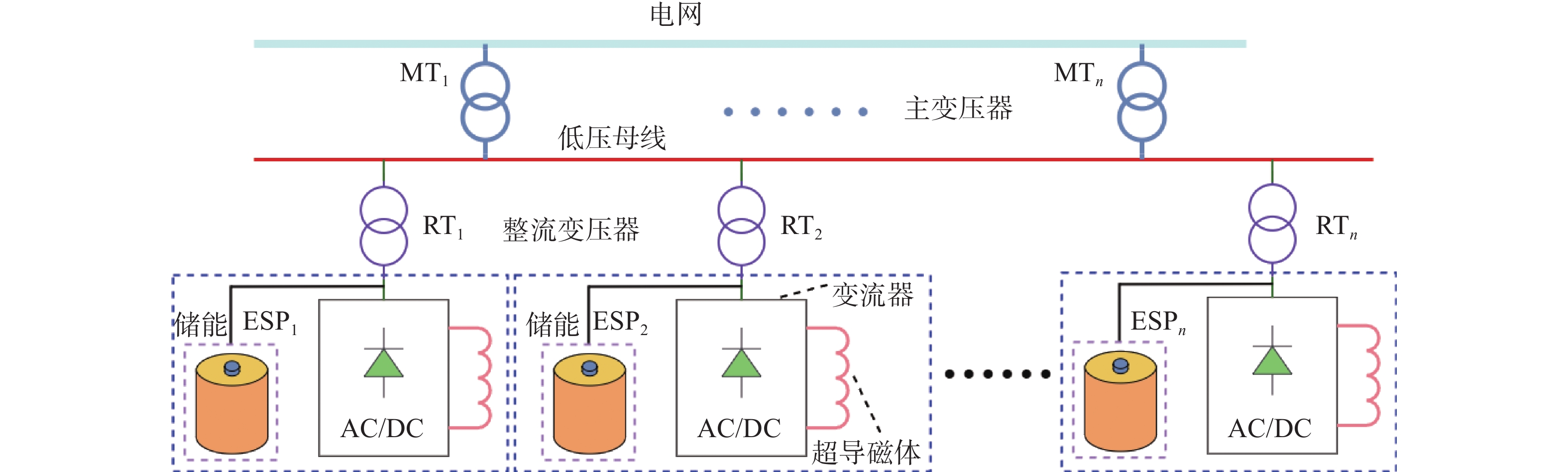
    • 分布式储能电源拓扑如图3所示,将储能装置分散地部署到每个超导磁体的整流变压器二次侧。负载所需要的脉冲功率由储能装置提供,脉冲功率不经过主变压器和整流变压器。与传统的变流器拓扑相比,这种拓扑节省了主变压器和整流变压器的容量。但是由于每个储能装置只能就近补偿处在同一个整流变压器二次侧的负载,容量利用率不高,造成了一定程度的资源浪费。

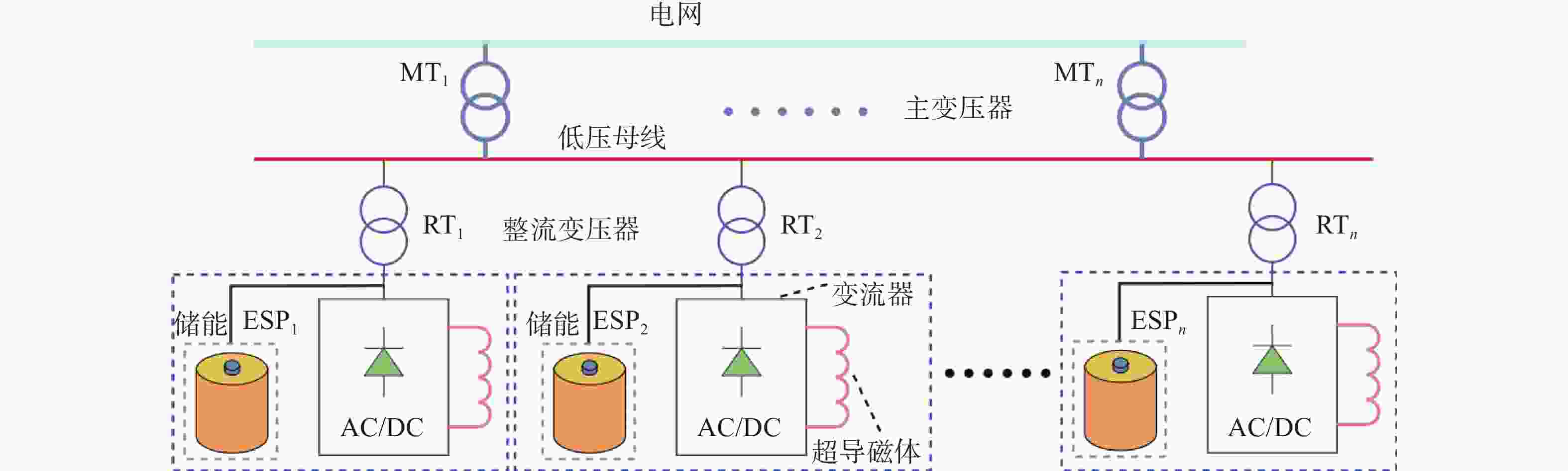
      Figure 3.  Distributed energy storage power supply topology

      这种拓扑的参数计算如下:

      步骤1:首先划分稳态功率和脉冲功率。根据仿真结果,使用三倍平均值来等效替代稳态值,计算过程如下:

      $$ {P}_{i,{\mathrm{st}}}=3\times \mathrm{m}\mathrm{e}\mathrm{a}\mathrm{n}\left(\left|{P}_{i}\left(t\right)\right|\right) $$ (5)

      式中:

      $ {P}_{i,st} $ ——第i个磁体的稳态功率值(MW);

      $ \mathrm{m}\mathrm{e}\mathrm{a}\mathrm{n}$ ——平均值函数。

      步骤2:计算整流变压器的容量。

      $$ {P}_{i,{\mathrm{RT}}}={P}_{i,{\mathrm{st}}} $$ (6)
      $$ {C}_{i,{\mathrm{RT}}}\geqslant 1.35\times {P}_{i,{\mathrm{RT}}} $$ (7)

      步骤3:计算主变压器的容量。

      $$ {C}_{{\mathrm{MT}}}\geqslant 1.35\times \sum {P}_{i,{\mathrm{RT}}} $$ (8)

      步骤4:计算储能装置的容量。

      $$ {P}_{i,E}\geqslant \mathrm{m}\mathrm{a}\mathrm{x}(\left|{P}_{i}\left(t\right)\right|-{P}_{i,{\mathrm{RT}}}) $$ (9)
      $$ {E}_{i}\left(t\right)={\int }_{0}^{t}{P}_{i}\left(x\right){\mathrm{d}}x $$ (10)
      $$ {C}_{i,E}\geqslant 1.35\times \mathrm{m}\mathrm{a}\mathrm{x}\left({E}_{i}\right(t\left)\right) $$ (11)

      式中:

      $ {P}_{i,E} $ ——第i个超导磁体的储能装置需要输出的功率值(MW);

      $ {E}_{i}\left(t\right) $ ——第i个超导磁体所包含的能量(kWh);

      $ {C}_{i,E} $ ——第i个储能装置的容量(kWh)。
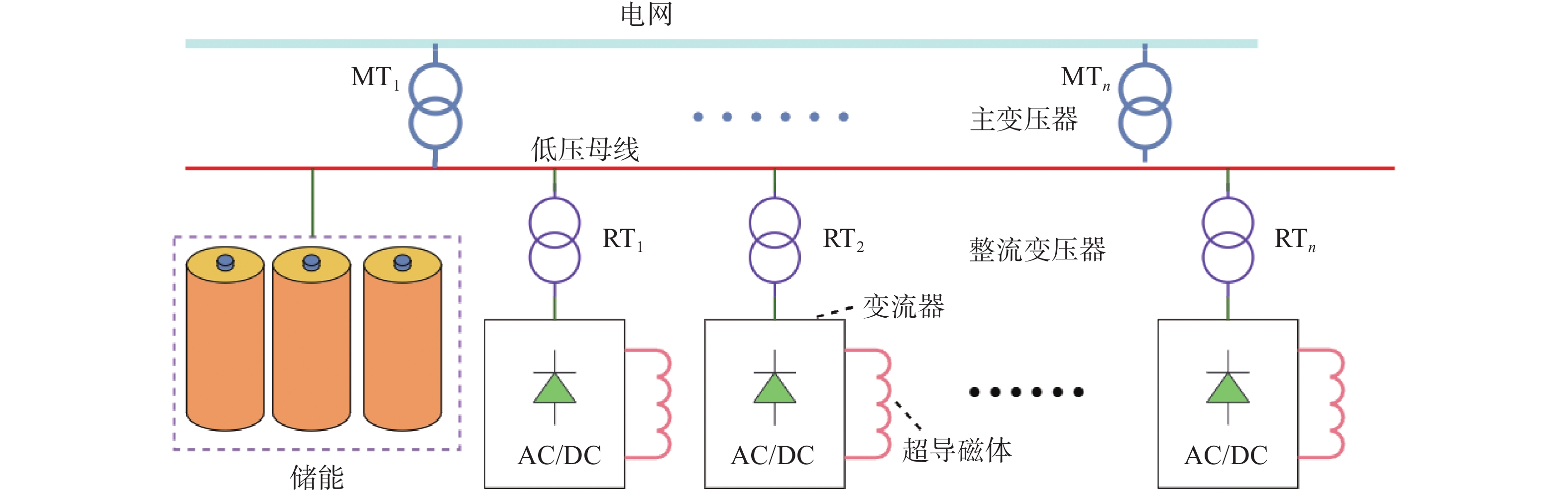
    • 图4所示,集中式拓扑的特点是将储能装置集中部署到主变压器二次侧的母线上,负载所需要的脉冲功率由储能元件提供。这种方式可减小了主变压器的容量。在这个拓扑中,能量从储能元件到超导磁体的过程中仍然需要经过整流变压器,所以与传统的变流器拓扑对比,整流变压器的容量没有降低。由于储能元件集中部署,相比于分布式拓扑,其容量利用率大大提高,所需的容量有所减小,节约了一部分成本。

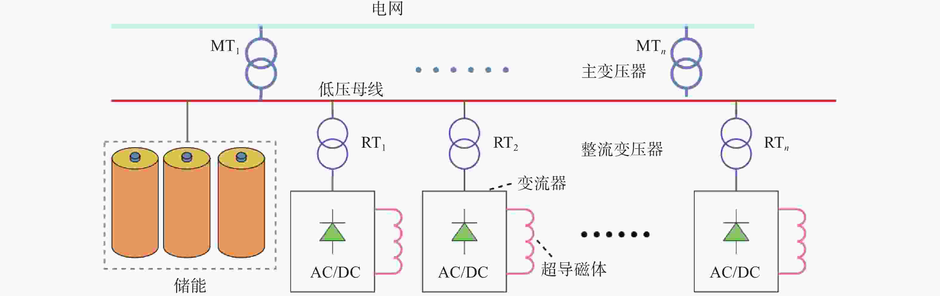
      Figure 4.  Centralized energy storage power supply topology

      这种拓扑的参数计算如下:

      步骤1:同2.1中的步骤1,使用公式(5)求稳态功率值。

      步骤2:计算主变压器的容量。

      $$ {P}_{{\mathrm{MT}}}=\left|{P}_{{\mathrm{all}}.{\mathrm{st}}}\right| $$ (12)
      $$ {C}_{{\mathrm{MT}}}\geqslant 1.35\times {P}_{{\mathrm{MT}}} $$ (13)

      式中:

      $ {P}_{all.st} $——所有磁体稳态功率之和(MW)。

      步骤3:计算整流变压器的容量,数值和计算方法与2.1中相同。

      $$ {P}_{i,{\mathrm{RT}}}=\mathrm{m}\mathrm{a}\mathrm{x}\left(\left|{P}_{i}\left(t\right)\right|\right) $$ (14)
      $$ {C}_{i,{\mathrm{RT}}}\geqslant 1.35\times {P}_{i,{\mathrm{RT}}} $$ (15)

      步骤4:计算储能装置的容量。

      $$ {P}_{E}\geqslant \mathrm{m}\mathrm{a}\mathrm{x}\left(\left|{P}_{{\mathrm{all}}}\left(t\right)\right|\right)-{P}_{{\mathrm{MT}}} $$ (16)
      $$ E\left(t\right)={\int }_{0}^{t}{P}_{{\mathrm{all}}}\left(x\right){\mathrm{d}}x $$ (17)
      $$ {C}_{E}\geqslant 1.35\times \mathrm{m}\mathrm{a}\mathrm{x}\left(E\right(t\left)\right) $$ (18)

      式中:

      $ {P}_{{\mathrm{all}}}\left(t\right) $——所有超导磁体总功率的瞬时值(MW);

      $ {C}_{E} $ ——储能装置的容量(kWh)。

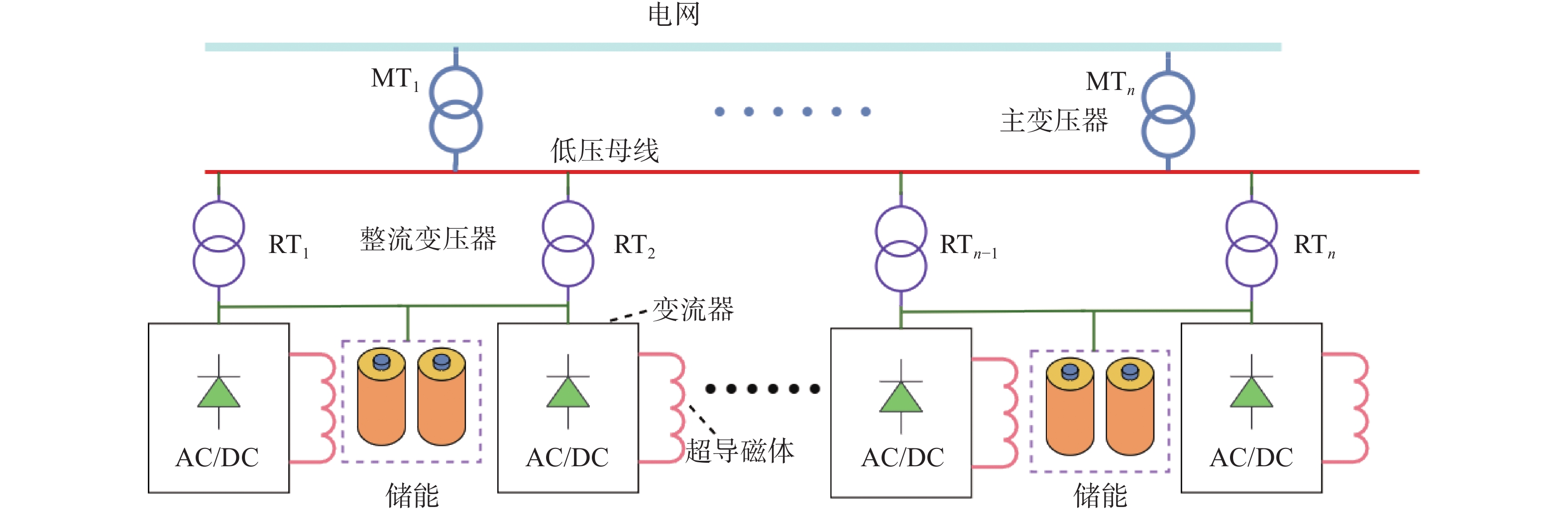
    • 混合式拓扑的结构如图5所示,它是分布式拓扑的改进型,将储能装置连接到多个整流变压器二次侧,使多个超导磁体共用一个储能装置。

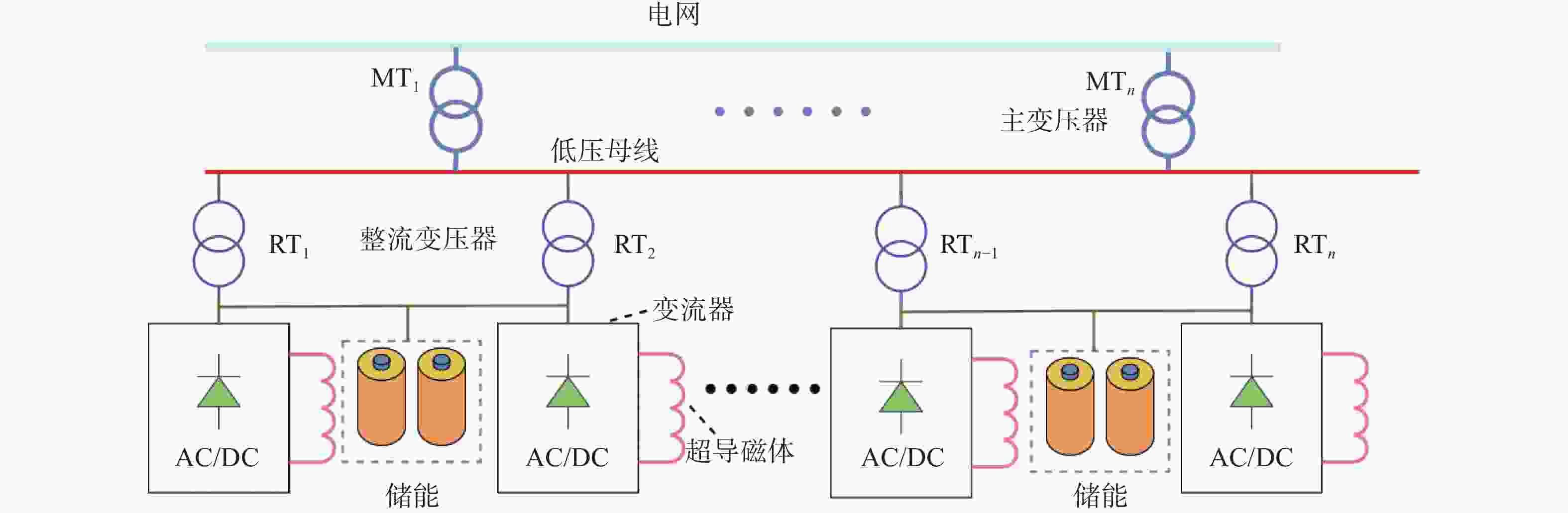
      Figure 5.  Hybrid energy storage power supply topology

      与分布式拓扑对比,这样的好处是节省储能装置的容量。原因在于不同磁体所需的功率和能量之间存在一定的互补关系。如果二者共用一套储能装置,可以节省储能装置的容量,而且这种拓扑还具有分布式拓扑的优点,可同时节省整流变压器的容量。基于此原理,该拓扑可以有效降低储能装置的容量,同时也不需要大容量的整流变压器和主变压器,节约了成本。

      然而,混合式拓扑的控制难度明显高于另外两种拓扑,它需要控制系统合理分配有限的功率和能量。除此之外,同一个储能装置连接了多个磁体,缺乏有效的隔离,为系统的安全运行带来了一定的隐患,也为电源系统和超导磁体的保护工作带来了一定的难度。

      这种拓扑的参数计算如下:

      步骤1:主变压器和整流变压器的容量方法计算与2.2章节中的步骤1、步骤2以及步骤3一致,故不再赘述。

      步骤2:筛选出适合共用一个储能装置的磁体电源。一般采用遍历循环的方式,也可使用优化算法,寻找出价格最低的最优组合。

      步骤3:计算储能系统的容量。为了便于说明,假设超导磁体i和超导磁体j共用一个储能装置。

      $$ {P}_{E,(i,j)}\geqslant \mathrm{m}\mathrm{a}\mathrm{x}(\left|{P}_{i}\left(t\right)+{P}_{j}\left(t\right)\right|-\left|{P}_{i,{\mathrm{st}}}+{P}_{j,{\mathrm{st}}}\right|) $$ (19)
      $$ {E}_{i,j}\left(t\right)={\int }_{0}^{t}{P}_{i}\left(x\right)+{P}_{j}\left(x\right){\mathrm{d}}x $$ (20)
      $$ {C}_{E}\geqslant 1.35\times {\mathrm{m}\mathrm{a}\mathrm{x}(E}_{i,j}\left(t\right)) $$ (21)

      式中:

      $ {P}_{E,(i,j)} $ ——储能装置的功率容量(MW);

      $ {E}_{i,j}\left(t\right) $ ——磁体i和磁体j所需求的能量(kWh)。

    • 为了证明储能式新型聚变电源在经济上的可行性,选取国际热核聚变实验堆组织(ITER)DINA simulation of 15MA DT scenario: 2010-01场景的仿真数据进行成本计算。

      首先利用上文中提到的计算公式,对新型电源系统中的主要元器件进行容量计算。再根据计算得到的容量进行参数选型,并确定其价格。一般来说,电气设备的报价都会随时间变化,为保证成本比较的公平性,所有变压器报价来自参考文献[10]。为了满足长时间高倍率的放电需求,储能设备初步选择为锂离子电池[26-30],报价来自参考文献[31-32]。

    • 主变压器和整流变压器的参数及价格如表2表3所示。储能装置的参数与价格如表4表5所示。

      拓扑电压等级/kV容量/MVA变压器价格/ M $高压变电站价格/ M $
      传统电源拓扑220360223
      分布式储能电源拓扑1102501.65.7
      集中式储能电源拓扑11012015.7
      混合式储能电源拓扑1102501.65.7

      Table 2.  Main transformer parameters and prices

      拓扑 PF1 PF2 PF3 PF4 PF5 PF6 CS1 CS2U CS2L CS3U CS3L
      传统电
      源拓扑
      容量/MW 65 80 140 85 115 45 175 65 80 115 45
      成本/M $ 1.35 1.4 2 1.45 1.7 1 2.8 1.35 1.4 1.7 1
      分布式
      储能电
      源拓扑
      容量/MW 10 30 45 30 60 30 45 30 30 10 10
      成本/M $ 0.18 0.4 1 0.4 1.25 0.4 1 0.4 0.4 0.18 0.18
      集中式
      储能电
      源拓扑
      容量/MW 65 80 140 85 115 45 175 65 80 115 45
      成本/M $ 1.35 1.4 2 1.45 1.7 1 2.8 1.35 1.4 1.7 1
      混合式
      储能电
      源拓扑
      容量/MW 10 30 45 30 60 30 45 30 30 10 10
      成本/M $ 0.18 0.4 1 0.4 1.25 0.4 1 0.4 0.4 0.18 0.18

      Table 3.  Rectifier transformer parameters and prices

      拓扑 PF1 PF2 PF3 PF4 PF5 PF6 CS1 CS2U CS2L CS3U CS3L
      分布式
      储能电
      源拓扑
      功率/MW 41 40 58 41.6 50.7 15.5 100 44 41.5 63.9 27.7
      容量/kWh 177 111 396 301 471 459 549 176 182 187 119
      成本/M $ 2.1 2.0 3.0 2.2 2.7 0.8 5.1 1.7 1.6 1.9 1.4
      总成本/M $ 24.5
      集中式
      储能电
      源拓扑
      功率/MW 178.63
      容量/MWh 1.11
      成本/M $ 9.21

      Table 4.  Parameters of distributed and centralized energy storage

      拓扑 PF1和CS1 PF2和PF5 PF3和PF4 PF6和CS2L CS3U和CS3L CS2U
      功率/
      MW
      92.7 10.67 8.1 34.8 65.6 44
      容量/
      kWh
      403 577 692 611 296 176
      成本/
      M $
      4.735 75 6.777 5 0.578 1.892 75 3.354 1.694
      总成本/
      M $
      12.93

      Table 5.  Parameters of hybrid energy storage

    • 在加装储能装置后,变压器的容量明显下降。尤其是在分布式拓扑中,主变压器和整流变压器的成本大幅降低。在集中式拓扑中,整流变压器的容量没有减小,仅仅是降低了主变压器容量,通过表4中的数据可知,该拓扑对储能装置的容量要求较低,相比于分布式拓扑,储能装置的成本从2450万美元降低至921万美元,降低了62.41%。在表6中可以看到,集中式拓扑的总成本低于分布式拓扑。而表5所列出的混合式拓扑,储能装置的成本略高于集中式拓扑,但该拓扑的整流变压器容量与分布式拓扑的相同,远低于集中式拓扑,所以总成本最低。

      参数 主变
      压器
      高压
      变电站
      储能 整流
      变压器
      总成本
      传统电源拓扑价格/M $ 2 23 17.15 87.15
      分布式储能电源
      拓扑价格/M $
      1.6 5.7 24.5 5.79 82.59
      集中式储能电源
      拓扑价格/M $
      1 5.7 9.21 17.15 78.06
      混合式储能电源
      拓扑价格/M $
      1.6 5.7 12.93 5.79 71.02

      Table 6.  Cost comparison of the four topologies

      通过表6可知,在加装储能装置后,电源系统的总成本会有所下降。其中贡献最大的就是主变压器及高压变电站。因储能装置承担了高幅值的脉冲功率,主变压器的容量大大减小,接入电网的电压等级也由220 kV降至110 kV,节约了高压变电站的成本。同时,整流变压器也节约了大部分成本,尤其是在混合式拓扑中,通过两个功率互补的磁体共用一个储能装置,在降低储能装置的成本同时,还兼顾了整流变压器的成本,在这四种拓扑中成本最低。

    • 为应对聚变装置对电网的功率冲击,减小电源系统的设计冗余,一种附带储能装置的新型聚变电源拓扑被提出。聚变装置的脉冲功率由储能提供,稳态功率通过主变压器从电网中获取。实现脉冲功率与电网的解耦。

      传统的储能装置部署方式一般有分布式和集中式。为了降低新型电源的成本,将二者结合,提出混合式的新型电源拓扑结构。可同时降低整流变压器和储能装置的容量。

      最终,采用ITER电源系统的仿真数据进行成本计算。经过在不考虑控制系统成本的前提下,与传统变流器拓扑相比,混合式拓扑节约了20%的成本。

Reference (32)

Catalog

    /

    DownLoad:  Full-Size Img  PowerPoint
    Return
    Return