• Peer Review
  • Non-profit
  • Global Open Access
  • Green Channel for Rising Stars
Turn off MathJax
Article Contents

HUANG Ya, HUANG Zhengyi. Failure analysis and shielding effectiveness study of magnetic components in strong magnetic environments for magnetic confinement fusion devices [J]. Southern energy construction, 2024, 11(3): 1-11. DOI: 10.16516/j.ceec.2024-051 doi:  10.16516/j.ceec.2024-051
Citation: HUANG Ya, HUANG Zhengyi. Failure analysis and shielding effectiveness study of magnetic components in strong magnetic environments for magnetic confinement fusion devices [J]. Southern energy construction, 2024, 11(3): 1-11. DOI: 10.16516/j.ceec.2024-051 doi:  10.16516/j.ceec.2024-051

Failure Analysis and Shielding Effectiveness Study of Magnetic Components in Strong Magnetic Environments for Magnetic Confinement Fusion Devices

doi: 10.16516/j.ceec.2024-051
  • Received Date: 2024-02-26
  • Accepted Date: 2024-03-13
  • Rev Recd Date: 2024-03-10
  •   Introduction  The purpose of this study is to explore the impact of the spatial magnetic field generated by nuclear fusion devices on magnetic devices and to gain an in-depth understanding of the magnetic field shielding characteristics in a complex electromagnetic environment.   Method  In the research process, the switch power supply and electronic transformer in the nuclear fusion internal power supply system were selected as the specific research objects. By analyzing in detail the impact of the magnetic field on the loss and the characteristic changes under different directions of the magnetic field, as well as by exploring the key factors affecting the magnetic field shielding effectiveness and the application of different materials, the research objectives were achieved.   Result  The results indicate that the loss of magnetic components significantly increases in a strong magnetic field environment, and the degree of influence of different directions of magnetic fields on component characteristics varies. By comparing and analyzing the shielding effects of different materials, it is found that materials with high conductivity and magnetic permeability have better application prospects in shielding design. Additionally, optimizing the shielding structure can further improve shielding effectiveness and reduce the impact of magnetic fields on magnetic components.   Conclusion  By systematically analyzing the impact of strong magnetic fields on magnetic components and the shielding effectiveness of nuclear fusion devices, key references are provided for testing the equipment's magnetic field tolerance and verifying shielding design. Future work will focus on further optimizing shielding materials and structural design to improve the stability and reliability of magnetic components in strong magnetic field environments.
  • [1] BIGOT B. Progress toward ITER's first plasma [J]. Nuclear fusion, 2019, 59(11): 112001. DOI:  10.1088/1741-4326/ab0f84.
    [2] SHIMADA M, CAMPBELL D J, MUKHOVATOV V, et al. Chapter 1: overview and summary [J]. Nuclear fusion, 2007, 47(6): S1-S17. DOI:  10.1088/0029-5515/47/6/S01.
    [3] ROCCELLA R. Static and transient magnetic field maps at level B1 tokamak complex [R]. France: ITER, 2015.
    [4] DC Magnetic induction immunity (IDM 696TB2) [M]. France: ITER Headquarter, 2011.
    [5] 许雪松, 黄亚, 雷红, 蒋力, 张杰, 王琨. ITER高功率磁场抗扰度测试系统研究 [J]. 南方能源建设, 2022, 9(2): 26-32. DOI:  10.16516/j.gedi.issn2095-8676.2022.02.003.

    XU Xuesong, HUANG Ya, LEI Hong, JIANG Li, ZHANG Jie, WANG Kun. Research on the High Power Magnetic Field Immunity Test System for ITER [J]. SOUTHERN ENERGY CONSTRUCTION, 2022, 9(2): 26-32. DOI:  10.16516/j.gedi.issn2095-8676.2022.02.003.
    [6] IEC. Electromagnetic compatibility (EMC) - Part 4-8: testing and measurement techniques-power frequency magnetic field immunity test: IEC 61000-4-8: 2009 [S]. IEC, 2009.
    [7] RAO Y. Test method for ITER equipment for static d. c. magnetic fields [R]. France: ITER, 2016.
    [8] 黄亚. ITER大口径均匀强磁兼容测试装备研制 [D]. 合肥: 中国科学技术大学, 2021. DOI:  10.27517/d.cnki.gzkju.2021.000074.

    HUANG Y. The development of the large-caliber uniform high intensity magnetic compatibility test equipment for ITER [D]. Hefei: University of Science and Technology of China, 2021. DOI:  10.27517/d.cnki.gzkju.2021.000074.
    [9] HUANG Y, FU P, JIANG L, et al. Design and error analysis of a large-caliber steady-state magnetic-field testing system [J]. IEEE transactions on magnetics, 2020, 56(4): 6000309. DOI:  10.1109/TMAG.2019.2958567.
    [10] HUANG Y, JIANG L, FU P, et al. Optimal design method to improve the magnetic field distribution of multiple square coil systems [J]. IEEE access, 2020, 8: 171184-171194. DOI:  10.1109/ACCESS.2020.3024653.
    [11] HUANG Y, JIANG L, FU P, et al. Temperature field calculation and water cooling design of the magnetic field immunity testing system [J]. Fusion engineering and design, 2021, 170: 112515. DOI:  10.1016/j.fusengdes.2021.112515.
    [12] LU Y W, YANG Y, JIANG L, et al. Analysis and design of the induction coil for a 2.1 m/120 mT magnetic field qualification test facility [J]. Fusion engineering and design, 2021, 166: 112302. DOI:  10.1016/j.fusengdes.2021.112302.
    [13] ZHANG M, WANG R M, YANG Y, et al. The preliminary design of large-scale high-intensity DC and power frequency magnetic field immunity test platform [J]. IEEE transactions on plasma science, 2020, 48(6): 1693-1697. DOI:  10.1109/TPS.2020.2982778.
    [14] LU Y W, YANG Y, ZHANG M, et al. Improved square-coil configurations for homogeneous magnetic field generation [J]. IEEE transactions on industrial electronics, 2022, 69(6): 6350-6360. DOI:  10.1109/TIE.2021.3094496.
    [15] 何燕. 高均匀性稳态磁场发生装置的优化研究 [J]. 南方能源建设, 2022, 9(2): 82-89. DOI:  10.16516/j.gedi.issn2095-8676.2022.02.011.

    HE Yan. Optimization of High Uniformity Steady-State Magnetic Field Generator [J]. SOUTHERN ENERGY CONSTRUCTION, 2022, 9(2): 82-89. DOI:  10.16516/j.gedi.issn2095-8676.2022.02.011.
    [16] MENG A H, LI M F, HE H L, et al. Dynamic coupling hysteresis model for giant magnetostrictive materials [J]. Advanced materials research, 2011, 311-313: 2262-2268. DOI:  10.4028/www.scientific.net/AMR.311-313.2262.
    [17] CHWASTEK K. Frequency behaviour of the modified Jiles-Atherton model [J]. Physica B:condensed matter, 2008, 403(13/16): 2484-2487. DOI:  10.1016/j.physb.2008.01.010.
    [18] HUANG W M, WANG B W, CAO S Y, et al. Dynamic strain model with eddy current effects for giant magnetostrictive transducer [J]. IEEE transactions on magnetics, 2007, 43(4): 1381-1384. DOI:  10.1109/TMAG.2006.891033.
    [19] WANG Y, LIU Z Z. Estimation model of core loss under DC bias [J]. IEEE transactions on applied superconductivity, 2016, 26(7): 0608905. DOI:  10.1109/TASC.2016.2594806.
    [20] WANG F H, GENG C, SU L. Parameter identification and prediction of Jiles-Atherton model for DC-biased transformer using improved shuffled frog leaping algorithm and least square support vector machine [J]. IET electric power applications, 2015, 9(9): 660-669. DOI:  10.1049/iet-epa.2015.0034.
    [21] YANG Y, SONG Z Q, JIANG L, et al. An improved two-coil configuration for low-frequency magnetic field immunity tests and its field inhomogeneity analysis [J]. IEEE transactions on industrial electronics, 2018, 65(10): 8204-8214. DOI:  10.1109/TIE.2018.2807420.
    [22] WANG S, QIU Y, TIAN J. Research on shielding effectiveness test of bulkhead in a compartment shelter [J]. IEEE transactions on electromagnetic compatibility, 2019, 61(1): 309-312. DOI:  10.1109/TEMC.2018.2801307.
    [23] XIAO P, DU P A, ZHANG B X. An analytical method for radiated electromagnetic and shielding effectiveness of braided coaxial cable [J]. IEEE transactions on electromagnetic compatibility, 2019, 61(1): 121-127. DOI:  10.1109/TEMC.2018.2814629.
  • 通讯作者: 陈斌, bchen63@163.com
    • 1. 

      沈阳化工大学材料科学与工程学院 沈阳 110142

    1. 本站搜索
    2. 百度学术搜索
    3. 万方数据库搜索
    4. CNKI搜索

Figures(19)

Article Metrics

Article views(26) PDF downloads(9) Cited by()

Related

Failure Analysis and Shielding Effectiveness Study of Magnetic Components in Strong Magnetic Environments for Magnetic Confinement Fusion Devices

doi: 10.16516/j.ceec.2024-051

Abstract:   Introduction  The purpose of this study is to explore the impact of the spatial magnetic field generated by nuclear fusion devices on magnetic devices and to gain an in-depth understanding of the magnetic field shielding characteristics in a complex electromagnetic environment.   Method  In the research process, the switch power supply and electronic transformer in the nuclear fusion internal power supply system were selected as the specific research objects. By analyzing in detail the impact of the magnetic field on the loss and the characteristic changes under different directions of the magnetic field, as well as by exploring the key factors affecting the magnetic field shielding effectiveness and the application of different materials, the research objectives were achieved.   Result  The results indicate that the loss of magnetic components significantly increases in a strong magnetic field environment, and the degree of influence of different directions of magnetic fields on component characteristics varies. By comparing and analyzing the shielding effects of different materials, it is found that materials with high conductivity and magnetic permeability have better application prospects in shielding design. Additionally, optimizing the shielding structure can further improve shielding effectiveness and reduce the impact of magnetic fields on magnetic components.   Conclusion  By systematically analyzing the impact of strong magnetic fields on magnetic components and the shielding effectiveness of nuclear fusion devices, key references are provided for testing the equipment's magnetic field tolerance and verifying shielding design. Future work will focus on further optimizing shielding materials and structural design to improve the stability and reliability of magnetic components in strong magnetic field environments.

HUANG Ya, HUANG Zhengyi. Failure analysis and shielding effectiveness study of magnetic components in strong magnetic environments for magnetic confinement fusion devices [J]. Southern energy construction, 2024, 11(3): 1-11. DOI: 10.16516/j.ceec.2024-051 doi:  10.16516/j.ceec.2024-051
Citation: HUANG Ya, HUANG Zhengyi. Failure analysis and shielding effectiveness study of magnetic components in strong magnetic environments for magnetic confinement fusion devices [J]. Southern energy construction, 2024, 11(3): 1-11. DOI: 10.16516/j.ceec.2024-051 doi:  10.16516/j.ceec.2024-051
    • 核聚变能是人类未来的理想能源,是各国竞相发展的科技制高点[1],磁约束聚变是依靠数万乃至数十万安培电流产生的强磁场约束等离子体。装置运行过程中周围会产生非常强的空间杂散磁场,以国际热核聚变实验堆ITER为例,当等离子体电流达到15 mA时[2],50 mT稳态空间磁场等值线在托卡马克主机装置周围覆盖半径高达25 m[3],由于结构紧凑,周围的测量、控制及诊断等辅助系统安装区域磁场普遍超过该值。

      磁性元件在核聚变装置各子系统中运用广泛,如:开关电源、电磁阀、传感器、变压器、继电器、电感器件、电机等。此类器件对空间磁场极为敏感,受到电磁干扰会发生失效现象,影响系统的可靠运行,已成为核聚变装置安全工作面临的关键问题之一。世界上首台全超导托卡马克EAST装置,运行经验表明大多数电子器件(阴极射线管、光电倍增器、闪烁探测器等)对直流磁场比较敏感。文献[4]中论述了Omron G6K继电器在超11 mT时就会出现不正常的工作状态,DCCT电流传感器对于10 mT的磁场会呈现(1~5)×10−6的漂移。

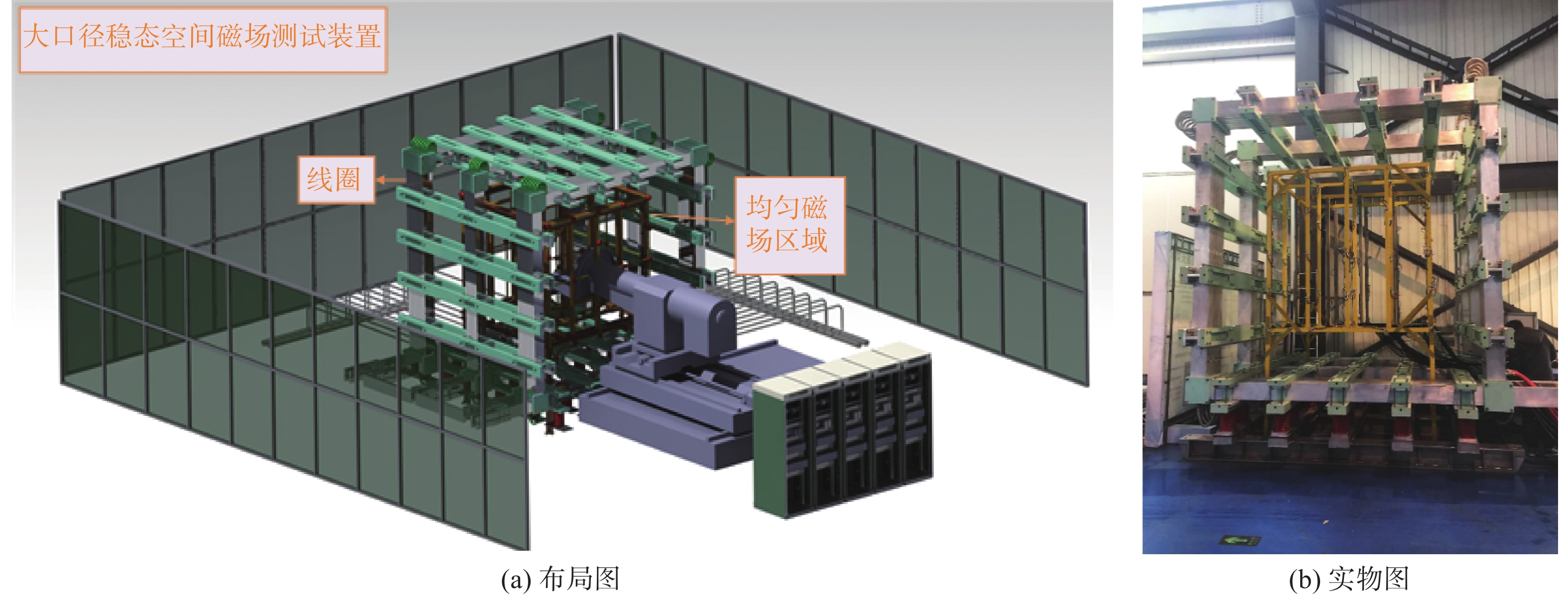
      ITER组织为了测试磁性元件的磁场耐受特性[5],针对现有的磁场抗扰度测试标准无法满足测试需求问题(如美国海军用标准、国际电工委员会标准[6]),专门制定了直流磁场抗扰度测试标准[7],并委托本团队研发了可产生2.1 m立方体空间均匀磁场的大口径稳态空间磁场测试装置,如图1所示,检验电子器件和电气设备的抗稳态空间磁场性能,文献[8]介绍了ITER大口径均匀强磁兼容测试装备的研制,为磁场屏蔽技术的实际应用提供了重要支持。同时,文献[9-11]等文献深入研究了不同材料、结构和设计对磁场屏蔽效能的影响,为优化磁场分布和提高屏蔽性能提供了理论依据。此外,文献[12-13]探讨了感应线圈的设计和改进,以及均匀磁场的产生[14-15],这些研究对于提高磁场测试的准确性和可靠性具有重要意义。同时科研工作者从磁性元件的模型上进行研究,对模型进行扩展发展到动态磁滞效应[16-17]、考虑涡流损耗[18]及直流偏置效应[19-20]的分析模型。文献[21-23]关注了屏蔽效能的测试方法和分析,为评估磁场屏蔽效果提供了有效手段。

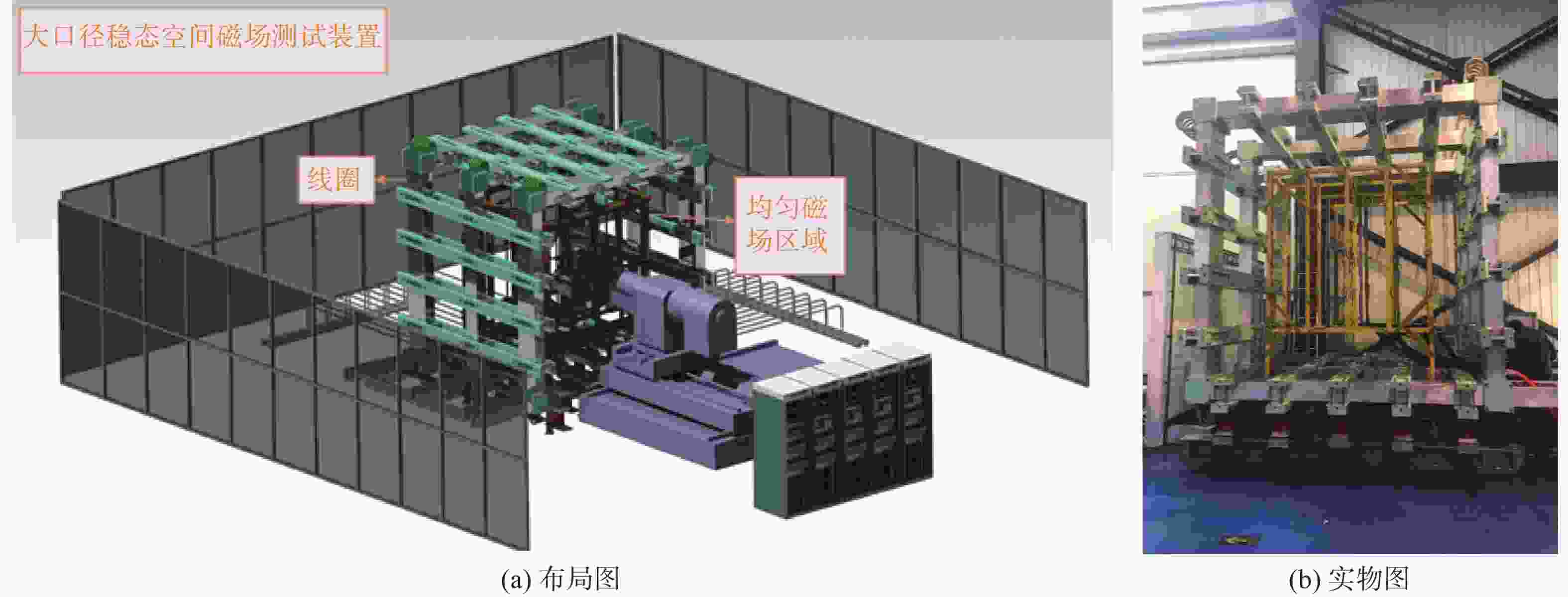
      Figure 1.  Large-caliber steady-state spatial magnetic field testing device

      测试结果表明:常用电子控制组件对磁场十分敏感,通过常规EMC(电磁兼容)测试的元件不能满足ITER现场对强磁场的耐受要求。

      国内外相关的科研成果虽然应用广泛但在复杂电磁环境的研究较少,而复杂电磁环境下干扰问题已直接影响聚变装置及相关设备的安全稳定运行。随着热核聚变、强电磁场、电磁发射等电源容量不断增加,产生的空间杂散磁场将更高更复杂,探索磁性元件工作特性对解决干扰问题具有重要的理论和现实意义。从本质上而言被干扰的根本原因在于磁性元件工作特性的改变,如电感阻抗减小引起过流、变压器变比降低导致输出电压跌落等。尽管目前对磁性元件的磁场干扰问题进行了初步分析并采取相应的屏蔽措施,但是在大型托卡马克聚变装置周围的磁性元件在复杂电磁环境下的故障特征并未得到系统的分析及实验验证,不能形成面向全局有效的研究手段及测试方法。

      文章紧密围绕ITER强稳态空间磁场干扰问题解决的迫切需求,针对磁性元件的主要共性问题,聚焦其背后的核心科学问题复杂电磁环境改变磁性元件工作特性开展系统研究,以分析较强空间磁场对磁性元件的作用规律,揭示较强空间磁场干扰的作用机理。通过研究,最终形成复杂电磁环境干扰问题的分析模型和方法,为磁性元件的抗干扰分析和屏蔽设计提供理论与技术支持,为保证ITER及未来大型托卡马克装置的可靠运行提供保障,同时可以更好地为国民经济和军用需求服务。

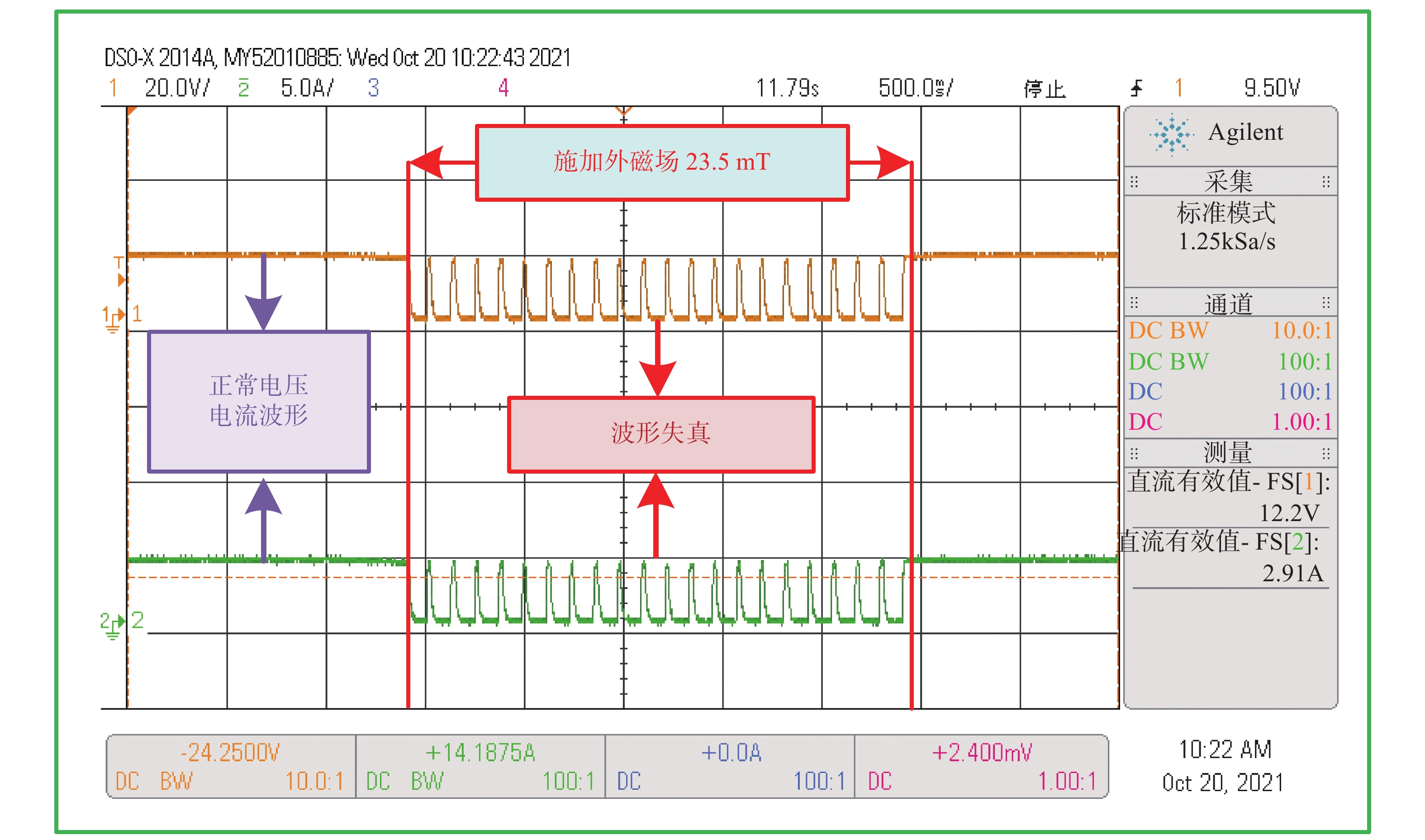
    • 在核聚变装置中,开关电源广泛应用在控制系统,保障各系统控制保护动作,但在外磁场达到23.5 mT时,该类电源输出失真畸变,不能正常输出,如图2所示。如此失效及误动作现象随核聚变装置容量增大,发生的频次和危害会进一步加大,因此分析和解决复杂电磁环境下的干扰问题,研究磁性元件的故障特征及保护措施,对于保障大型托卡马克聚变装置的可靠运行具有重大意义。

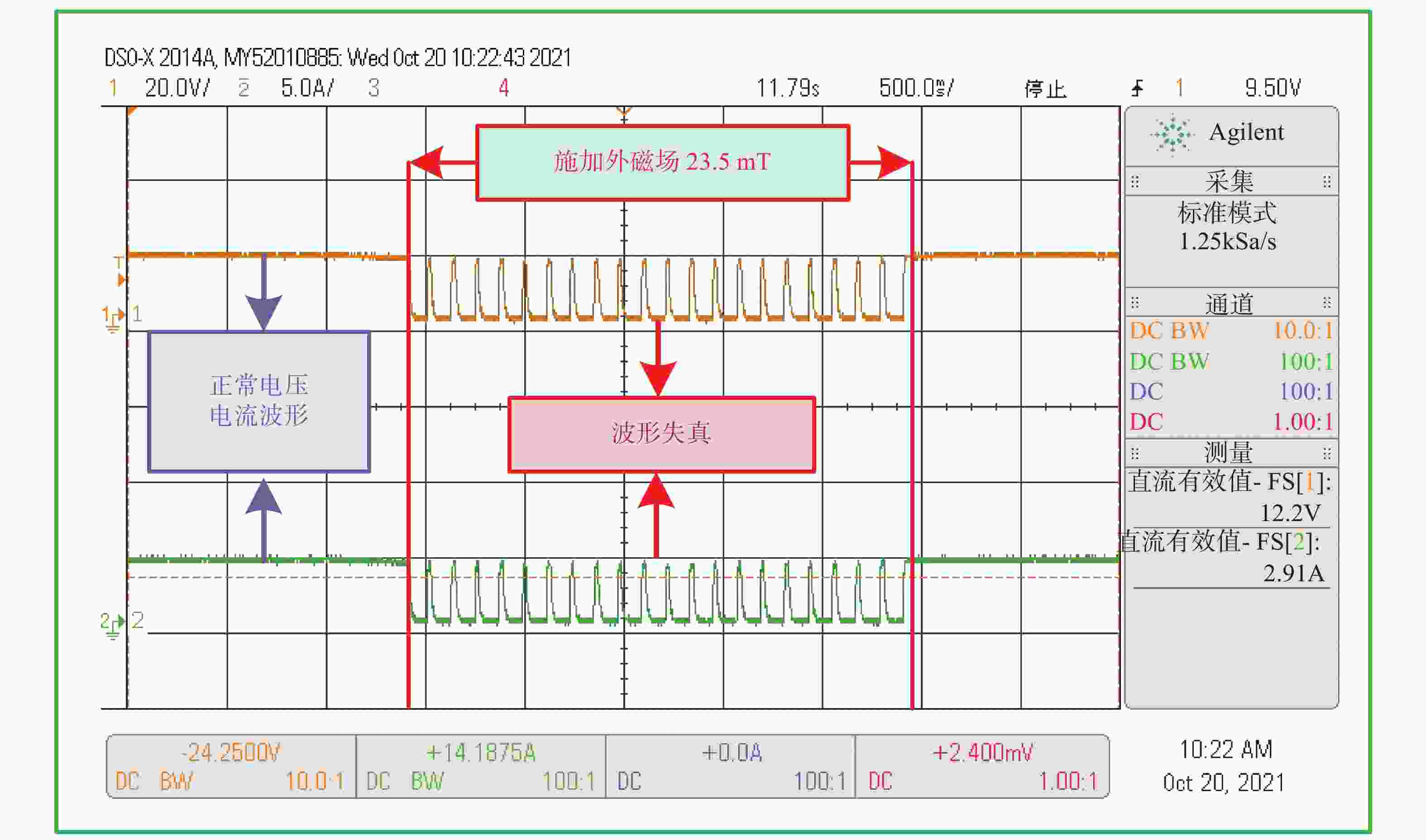
      Figure 2.  Analysis of output characteristics of switch power supply in external magnetic field environment

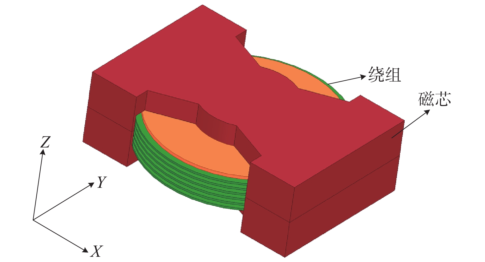
      变压器是开关电源非常重要的部件,起到电源转换、隔离的作用,由磁芯和绕组组成,如图3所示。变压器在运行期间,会产生磁场,同时绕组和磁芯中会产生损耗,当开关频率越高,损耗越大。分析其性能变化,确定此磁场对其的干扰作用。

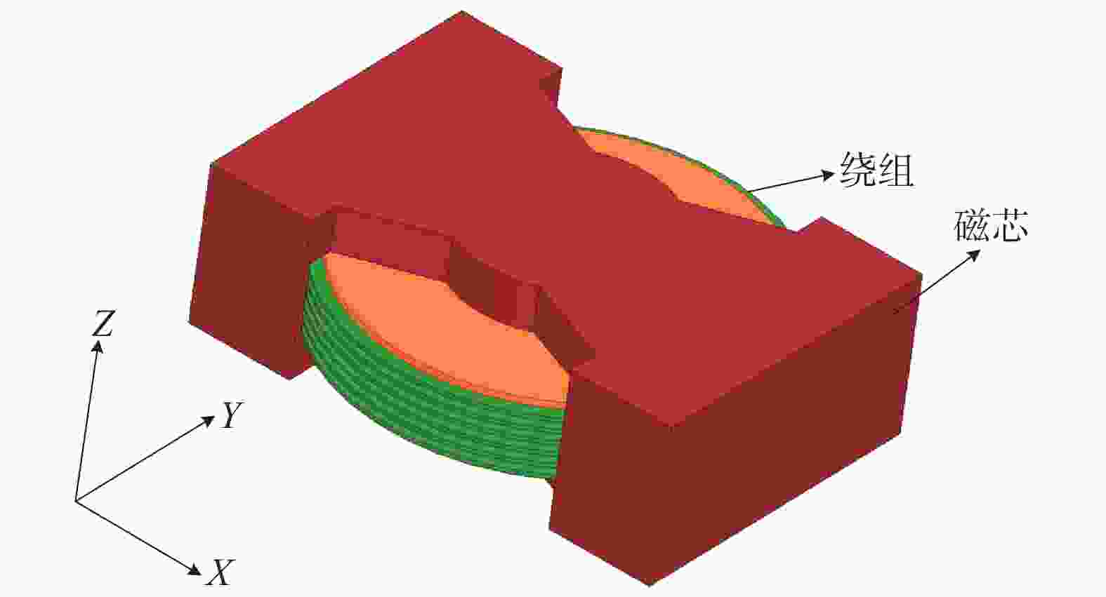
      Figure 3.  Model of transformer

      1)变压器磁芯损耗

      磁芯损耗是在交流磁通磁化时形成的能量损耗,会引起发热问题。其损耗与频率、磁感应强度、体积等有关。

      磁滞损耗,与开关频率呈正相关,有经验公式为:

      $$ P_{\mathrm{h}}=k_{\mathrm{h}}fVB_{\mathrm{m}}^{\alpha} $$ (1)

      式中:

      kh ——磁滞系数;

      f ——开关频率(Hz);

      V ——磁芯体积(m3);

      Bm ——磁感应强度(T);

      α ——斯坦梅兹系数。

      涡流损耗为:

      $$ P_{\mathrm{e}}=k_{\mathrm{e}}f^2VB_{\mathrm{m}}^2 $$ (2)

      式中:

      ke——涡流损耗系数。

      剩余损耗为:

      $$ P_{\mathrm{T}}=\eta f^{\delta}VB_{\mathrm{m}}^{\beta} $$ (3)

      式中:

      η ——损耗系数;

      δ ——频率的损耗指数;

      β ——磁感应的损耗指数。

      2)变压器绕组损耗

      绕组损耗与趋肤效应有关,其趋肤深度为:

      $$ \Delta = \dfrac{1}{{\sqrt {{\text{π}} f\gamma \mu } }} $$ (4)

      式中:

      γ ——导线的电导率(S/m);

      μ ——磁导率(H/m)。

      交、直流电阻的关系为:

      $$ {R_{{\mathrm{DC}}}} = {K_{\delta} } \times {R_{{\mathrm{AC}}}} $$ (5)

      式中:

      RDCRAC ——直流阻抗和交流阻抗(Ω);

      Kδ ——二者比值系数。

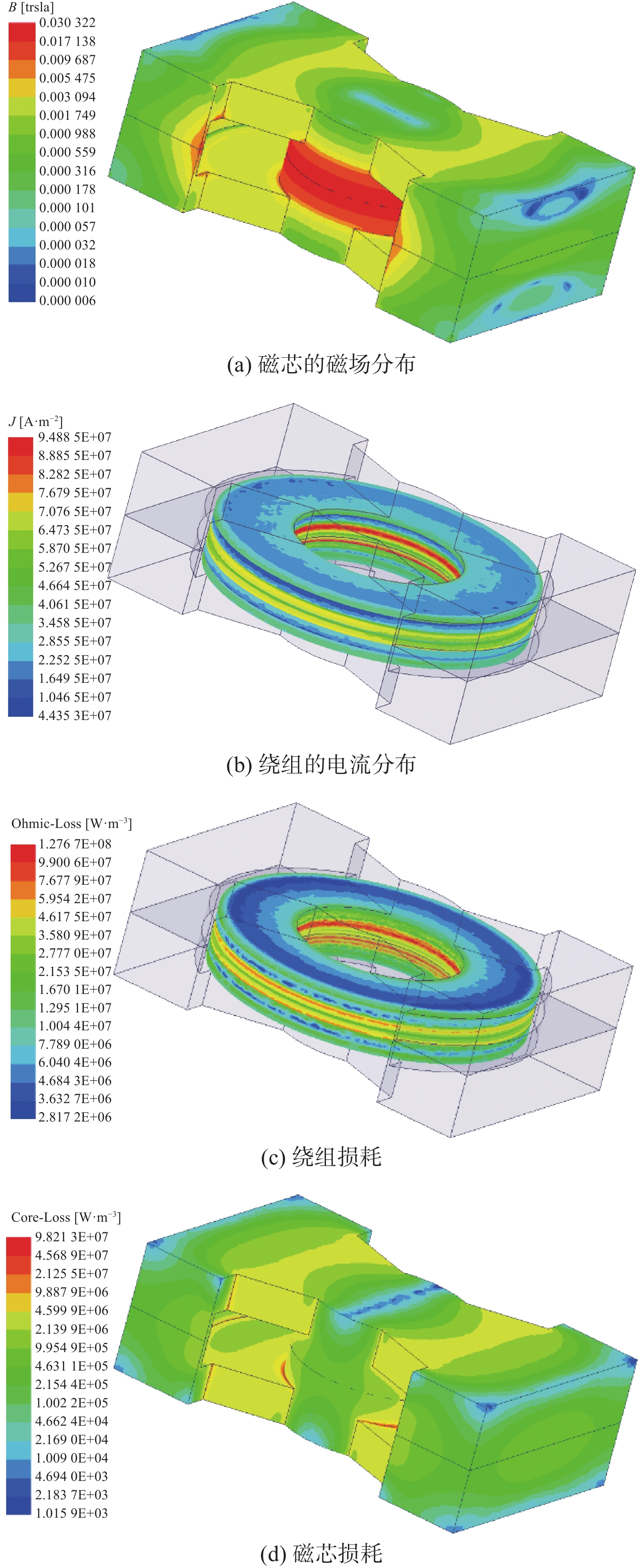
      无外界环境磁场下的变压器(100 kHz)电磁分布如图4所示。磁芯磁场主要集中在中间磁柱上,而电流损耗分布较为合理,计算得到磁芯损耗为1.768 W,绕组铜损耗为5.028 W,漏感为48.22 μH。

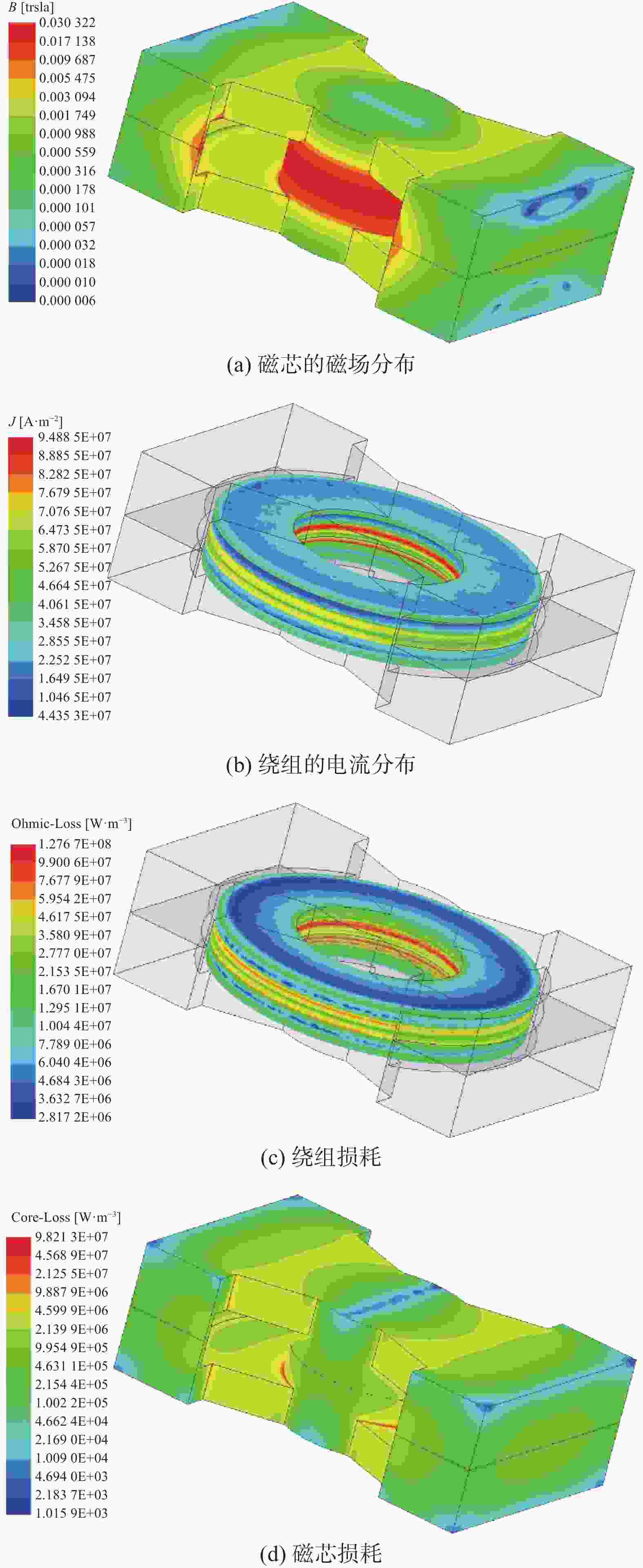
      Figure 4.  Electromagnetic distribution of transformers under no external magnetic field

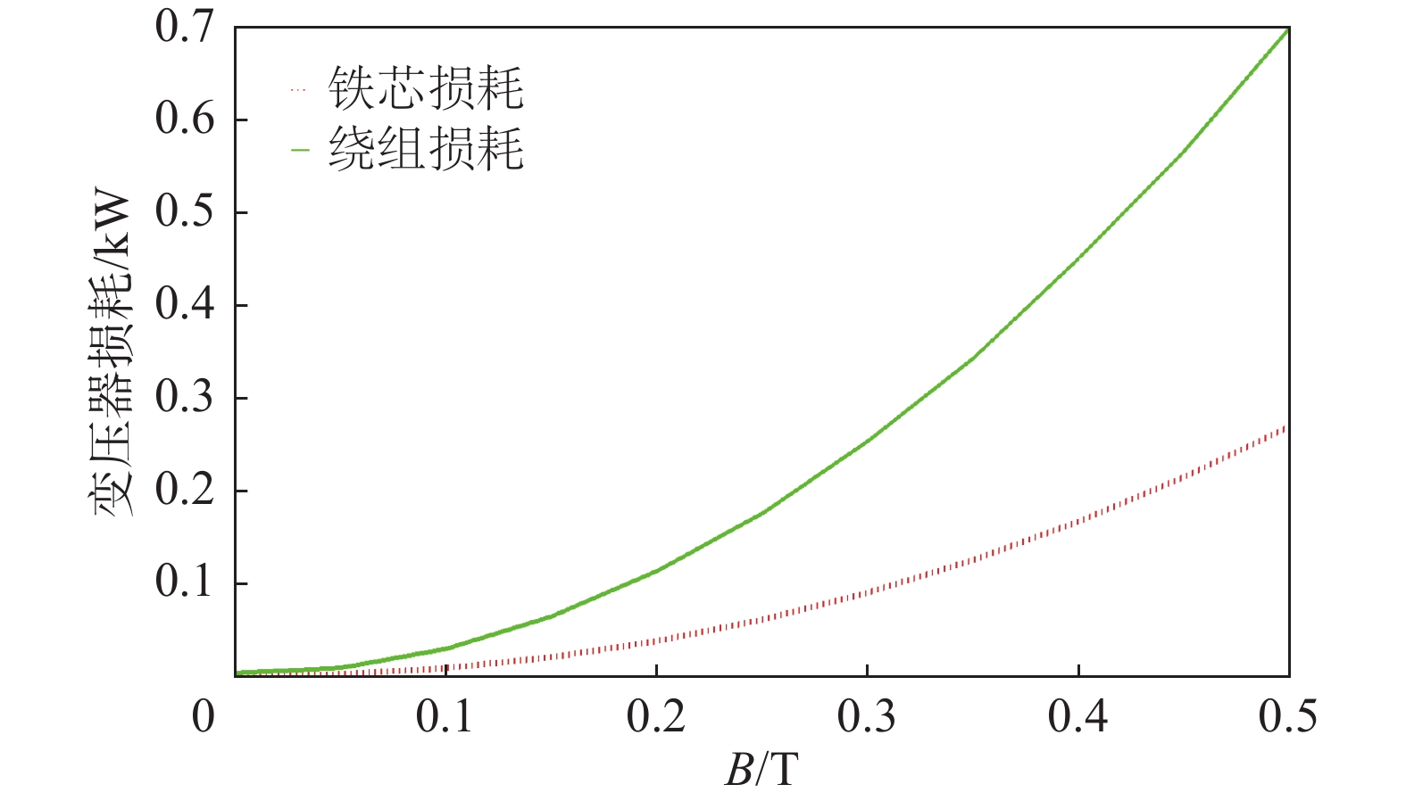
      通过计算不同外界环境、不同方向下的变压器铜耗和磁芯损耗的变化关系曲线(如图5 ~ 图7所示),可以发现,随着外界环境磁场的增强,变压器的铜耗和磁芯损耗都在增加。具体来说,当施加在X方向时,变压器的铜耗增大幅度较小,而磁芯损耗则迅速增大;当施加在Y方向时,变压器的磁芯损耗增大幅度较小,而铜耗却迅速增大;当施加在Z方向时,变压器的铜耗和磁芯损耗都有较大幅度的增加,且铜耗的增大幅度大于磁芯损耗。

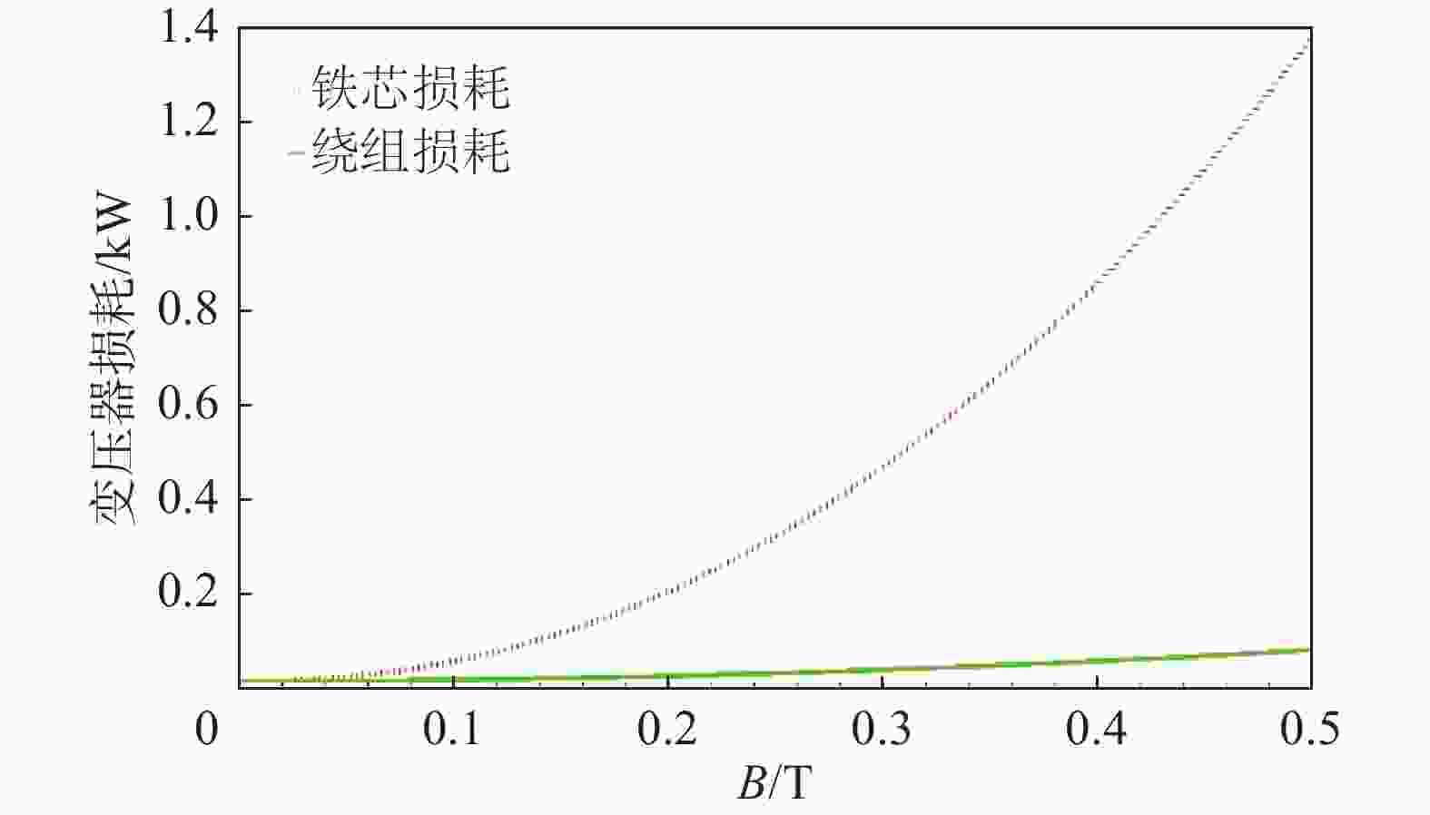
      Figure 5.  Relationship between the loss of transformers and the external magnetic field (X-direction)

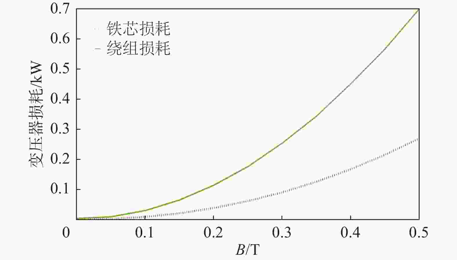
      Figure 7.  Relationship between the loss of transformers and the external magnetic field (Z-direction)

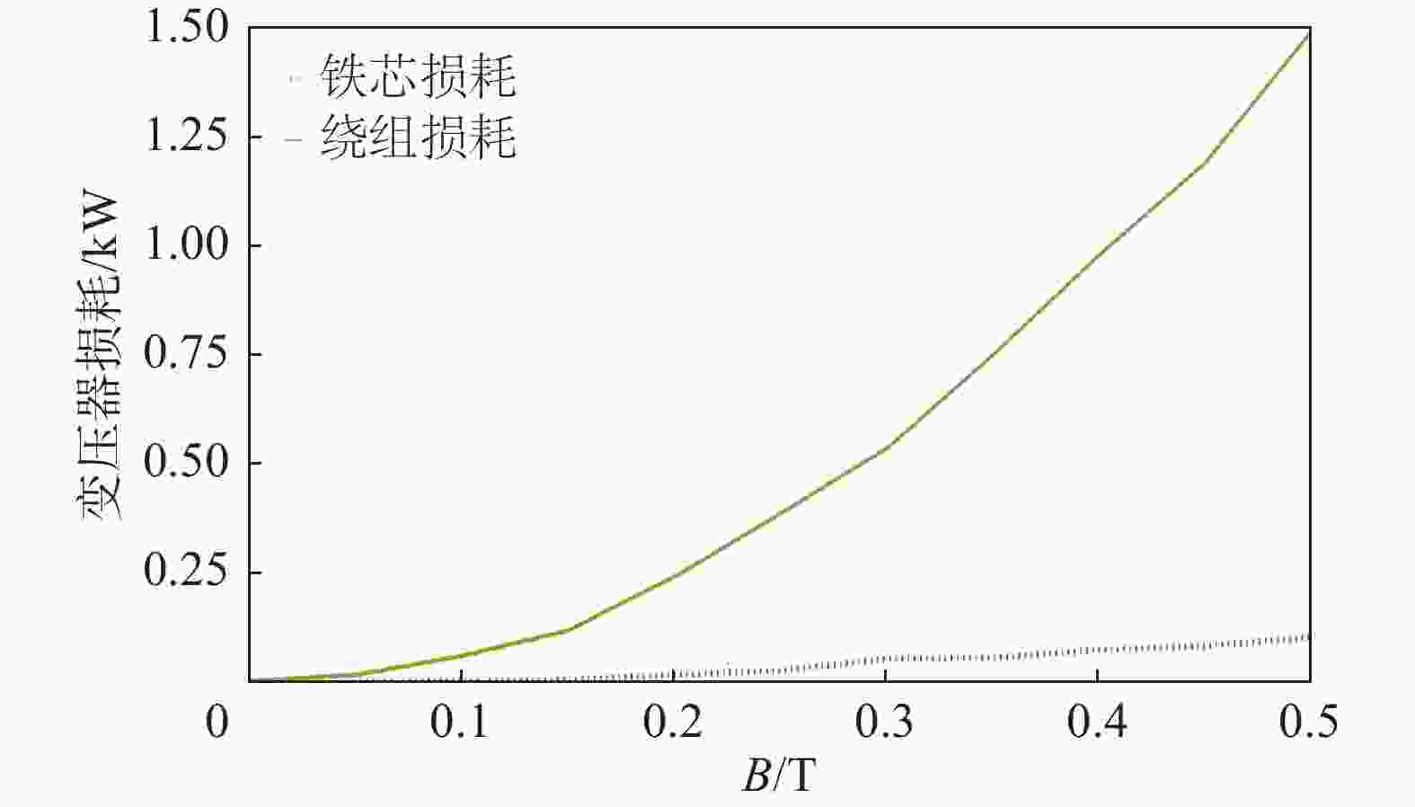
      Figure 6.  Relationship between the loss of transformers and the external magnetic field (Y-direction)

      以开关电源的电子变压器器件为对象,研究了外加磁场对磁性器件的特性影响。随着外磁场的不断增大,变压器具有输出特性下降和失效的现象,是实际托卡马克装置的器件失效具有较为典型的案例。

    • 在确定托卡马克磁性器件失效的根源,需要解决此类问题的发生,即电磁兼容问题。电磁屏蔽是将被保护装置包围起来,衰减和阻断传播途径,抑制外(内)部干扰源对内(外)部设备的影响[20-21]。屏蔽性能由屏蔽效能(单位:dB)表示。

      对于电场屏蔽效能为:

      $$ {S E_{\mathrm{d}}} = - 20\lg \dfrac{{{E_{\mathrm{s}}}}}{{{E_0}}} $$ (6)

      对于磁场屏蔽效能为:

      $$ {S E_{\mathrm{c}}} = - 20\lg \dfrac{{{H_{\mathrm{s}}}}}{{{H_0}}} $$ (7)

      式中:

      SEsSHs ——存在屏蔽时的响应;

      E0H0 ——不存在屏蔽时的响应。

      直流磁场主要通过消除或抑制干扰来处理。直流磁场的磁力线通常会优先通过低磁阻的路径。可以选择高磁导率材料(如铁、坡莫合金等)来进行屏蔽设计。低频磁场会随着距离的增加而衰减,如果无法远离磁场源,则需要进行屏蔽。同时,要注意材料的磁饱和问题,磁导率越高的材料越容易发生磁饱和。

      图8所示,方形屏蔽体(带开孔)可以看作是封闭的方形屏蔽体和开孔的完美导电(PEC)方形屏蔽体的叠加,总磁场也是通过叠加计算:B1=B2+B3

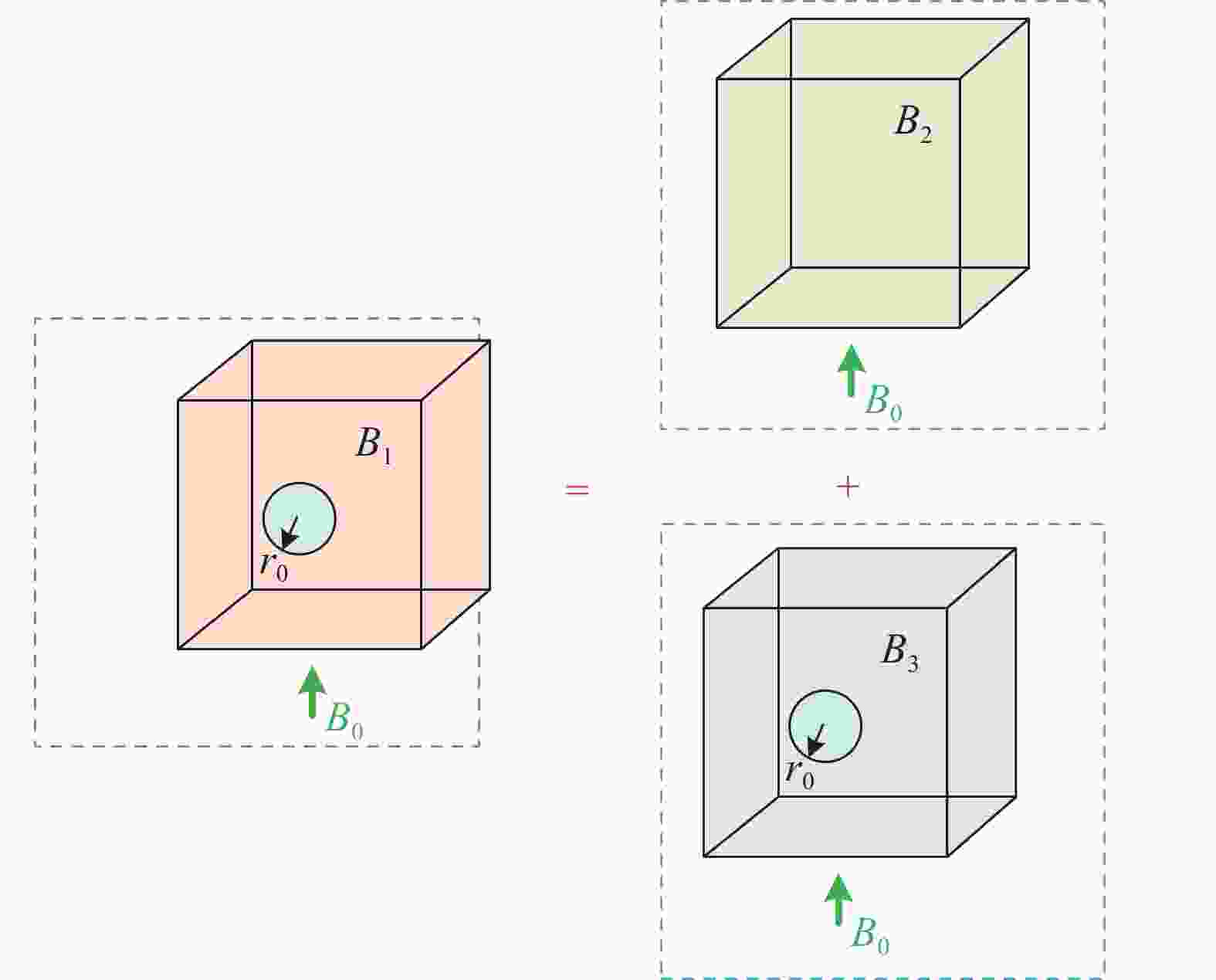
      Figure 8.  Model of perforated metal rectangular shielding body

      封闭的方形屏蔽体(封闭)尺寸为a×b×c,厚度为Δ,材料的电导率为σ,相对介电常数为εr,相对磁导率为μr,则其屏蔽效能可以通过形状因子进行近似计算:

      $$ S E=\left\{\begin{gathered}1+\frac{j\omega\mu_0\sigma V\Delta}{A},\ \Delta\ll\delta \\ \left(1+\frac{\gamma V\Delta}{\mu_{\mathrm{r}}A}\right)\frac{\mathrm{exp}({\gamma\Delta})}{2},\ \Delta\gg\delta\end{gathered}\right. $$ (8)

      式中:

      V ——屏蔽体的体积(m3),V = abc

      A ——屏蔽体的表面积(m2),A = 2(ab+bc+ca)。

      建立边长为1 m的正方体屏蔽体结构,厚度为d,如图9所示。选择铁和铝作为稳态磁场和瞬态磁场的屏蔽材料,在Z方向施加0.5 T的磁感应强度。

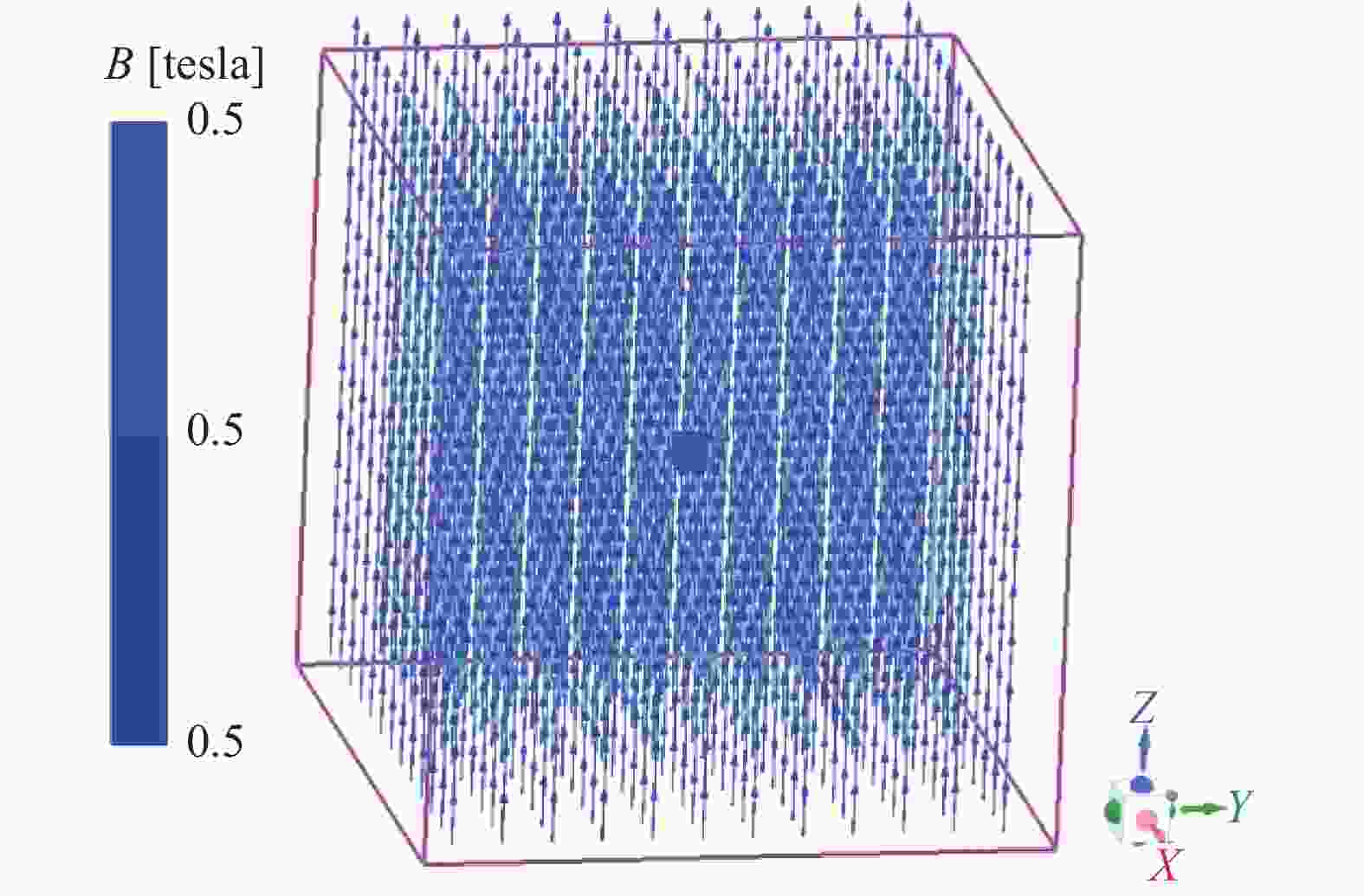
      Figure 9.  External magnetic field of cube shielding structure

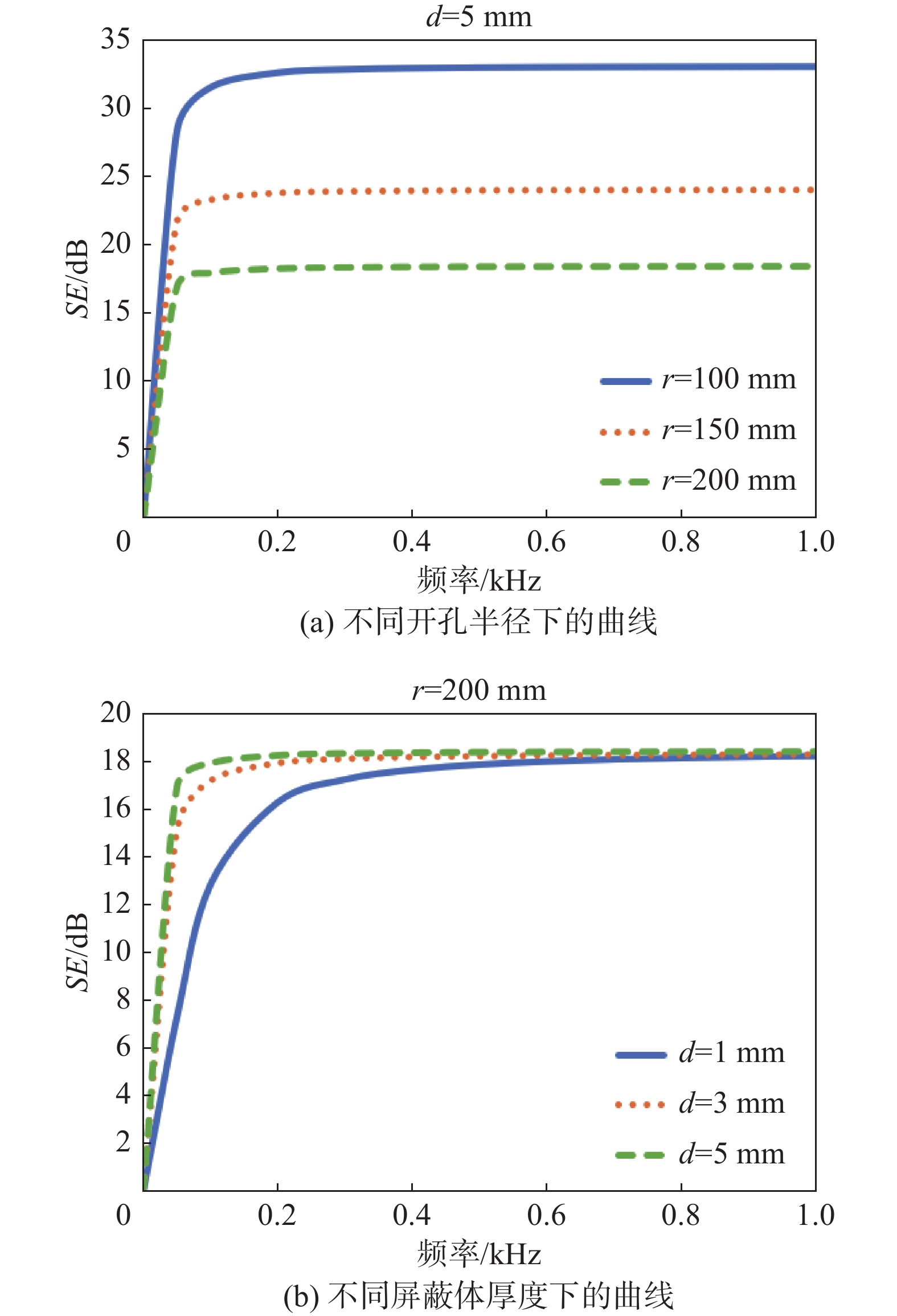
      当使用铝作为屏蔽材料时,在平行于轴的侧面开设一个半径为r的圆孔。通过计算得到不同开孔半径和不同导体厚度下的铝屏蔽体在不同频率下的屏蔽效能曲线分布,如图10所示。由此可见,随着频率的增加,铝材料的屏蔽效果越好。当频率达到临界值时,屏蔽效能不再增加,该临界值与屏蔽体厚度有关,与开孔尺寸无关。此外,随着开孔半径的增大,屏蔽效能会降低,频率效果也会变差;而随着屏蔽体厚度的增加,屏蔽效能会提高,频率效果也会更好。然而,随着频率的增大,最终的屏蔽效能将趋于一致。

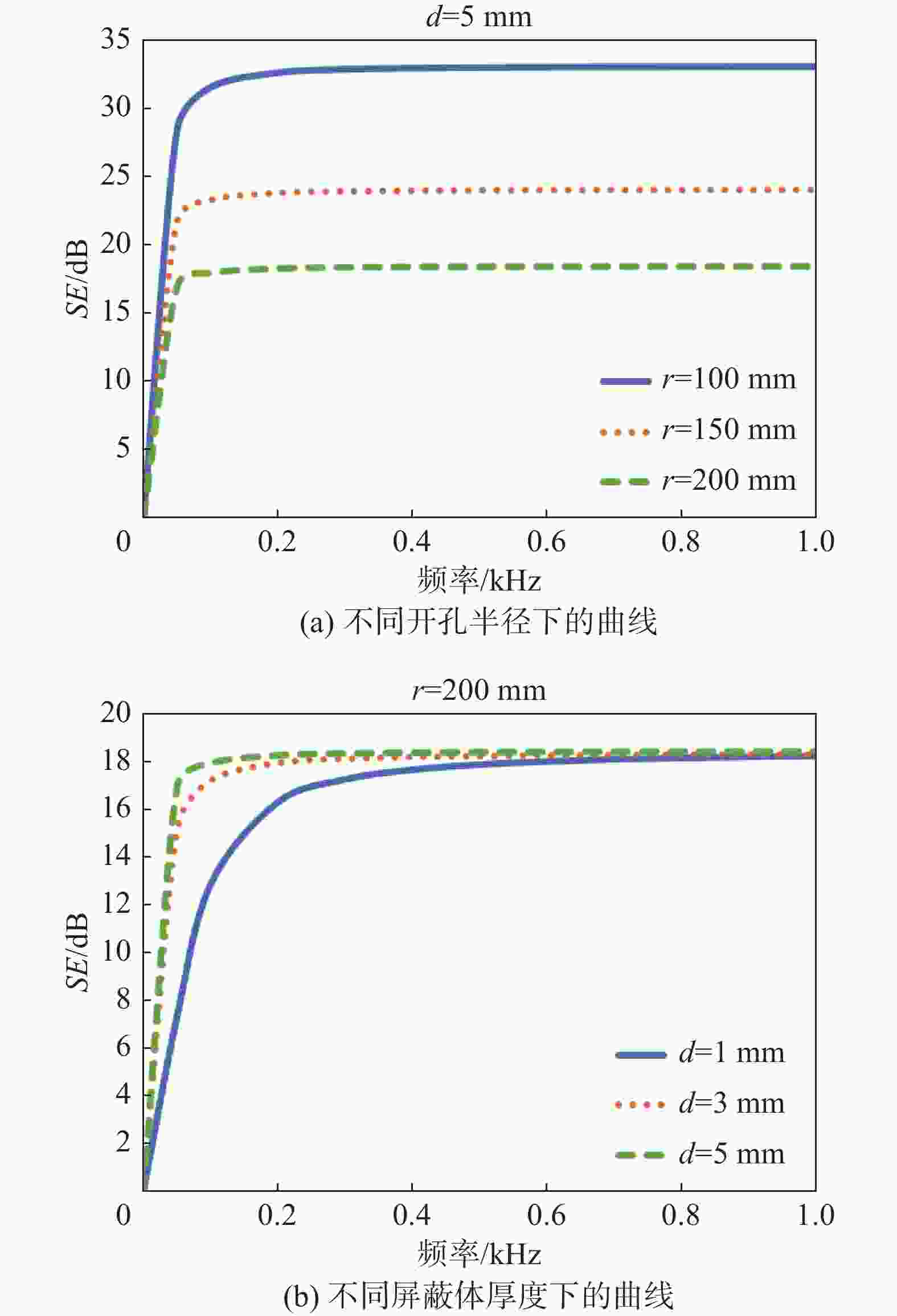
      Figure 10.  Relationship between shielding effectiveness and frequency

      经计算发现,铝材料对直流稳态磁场几乎没有屏蔽作用。因此,在屏蔽稳态磁场时,需要采用高磁导率材料(如铁)进行屏蔽设计。同样构建一个边长为1 m的正方体铁材屏蔽体结构,其屏蔽效能计算结果如图11所示。可以看出,开孔尺寸越小、屏蔽体厚度越大,屏蔽效能就越高,这表明屏蔽效果越好。

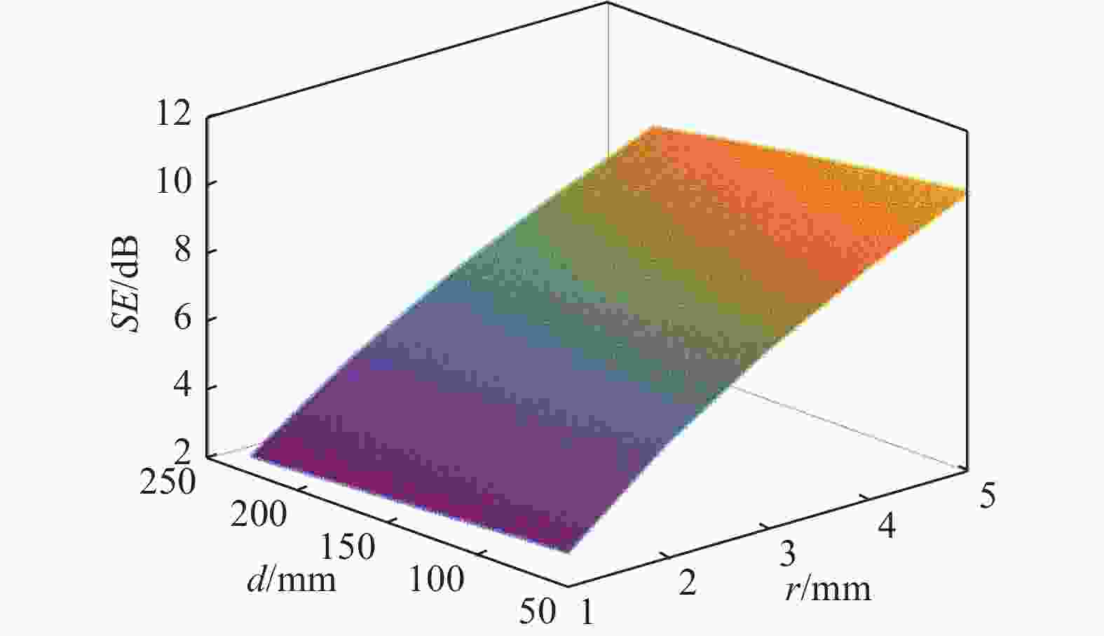
      Figure 11.  Relationship between shielding effectiveness of the center point of the iron shielding body and the frequency

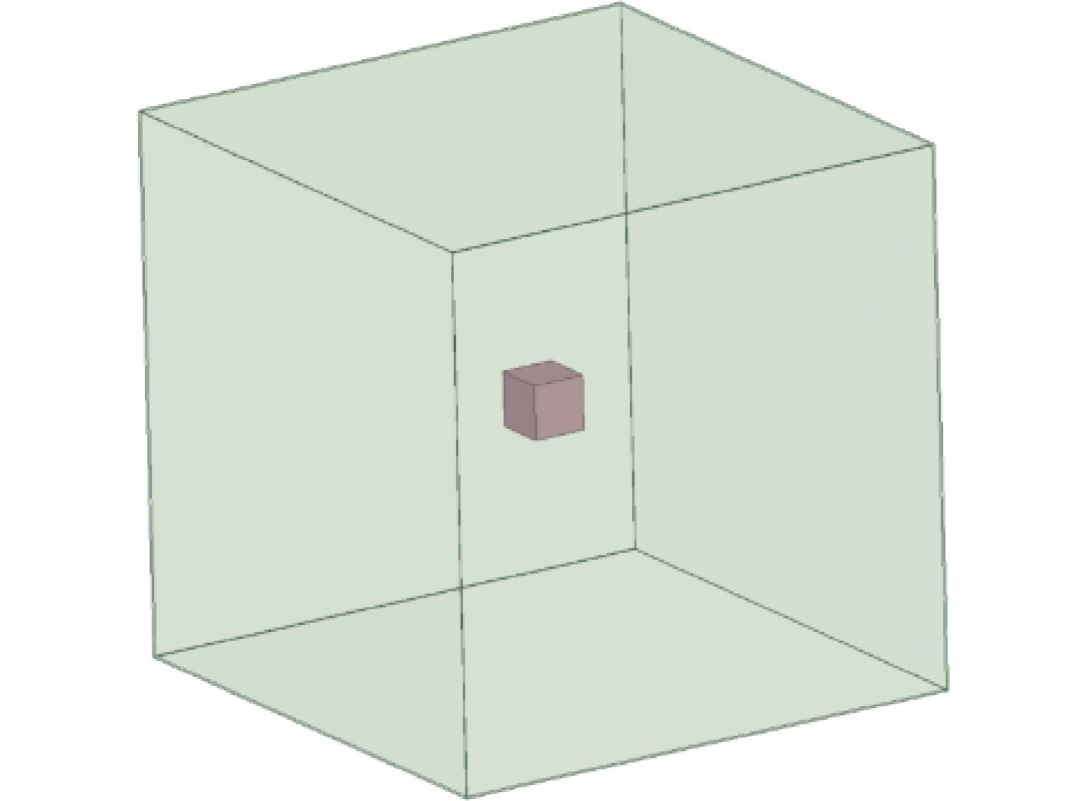
      超导聚变装置外围稳态磁场最大为200 mT,以开关电源20 mT为安全值,则屏蔽体的屏蔽效能最小需要做到SE = 20 dB。被保护的电力电子器件的尺寸不一,需要根据实际情况来计算,以100 mm的正方体空间为被测安全区域,保证在200 mT的磁场条件下,其内部的磁场不大于20 mT。设计全屏蔽结构如图12所示。

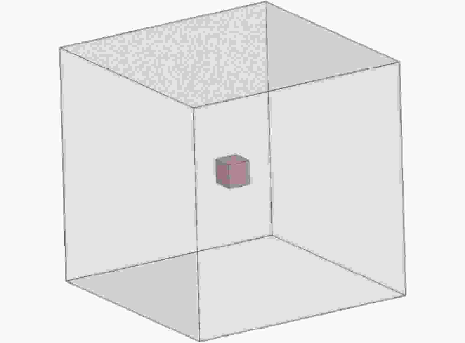
      Figure 12.  Fully shielded structure

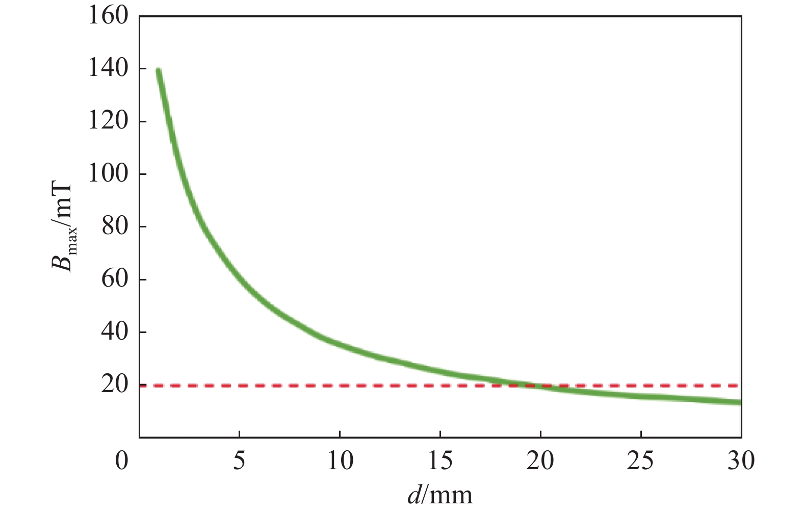
      为了确保内部100 mm的正方体空间的磁场最大值Bmax低于20 mT,需要不断增大屏蔽厚度,计算得到磁场最大值Bmax与屏蔽体厚度d的关系曲线如图13所示。随着厚度增大,磁场值越小,当厚度大于20 mm时才能满足低于最大磁场值20 mT的要求。实际情况需要根据器件本身的耐受磁场值,屏蔽材料选择、屏蔽结构的设计、安装位置的要求等条件实时设计。

      Figure 13.  Relationship between the maximum magnetic field and the thickness of the shielding body

    • 针对型号MEAN WELL NES-100-24开关电源,输出24 V、4.5 A的电源进行空间磁场抗扰度测试,使用稳态磁场抗扰度检测设备在测试开关电源的外磁场特性,同时利用三维磁场探针来实时捕捉空间磁场值,测试平台如图14所示。在开关电源三个方向不断施加磁场,直至开关电源输出特性发生变化,如图15所示。将外磁场从0 mT开始不断的呈阶梯式上升,测试电源的输出特性,当达到20 mT左右时候就出现输出失效的情况,随着磁场值不断上升,波形畸变越厉害,直至完全失效,可见开关电源对于外界空间磁场非常敏感,如图16所示。

      Figure 14.  Magnetic field testing platform

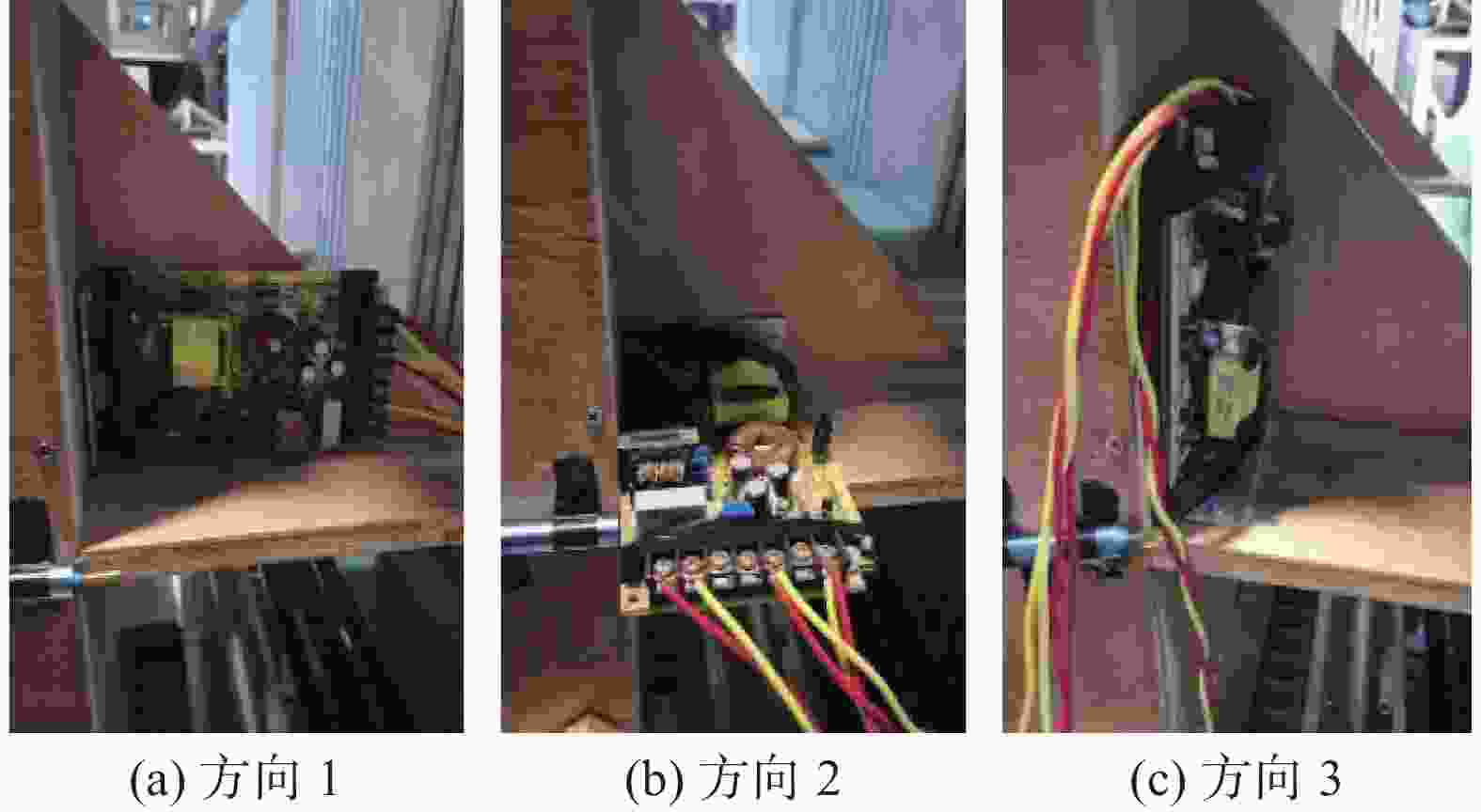
      Figure 15.  Switch power supplies located in different magnetic field directions

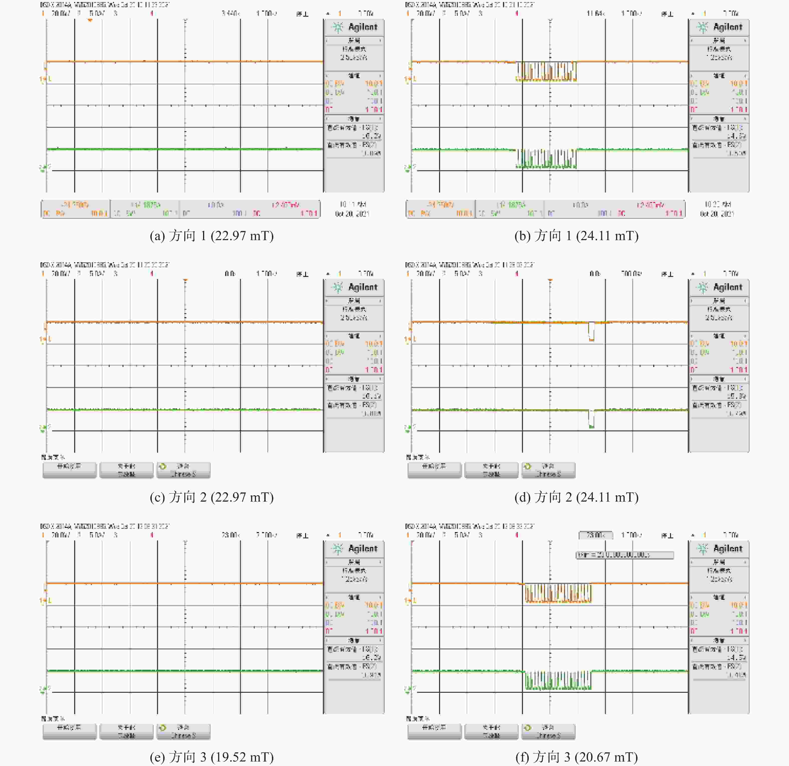
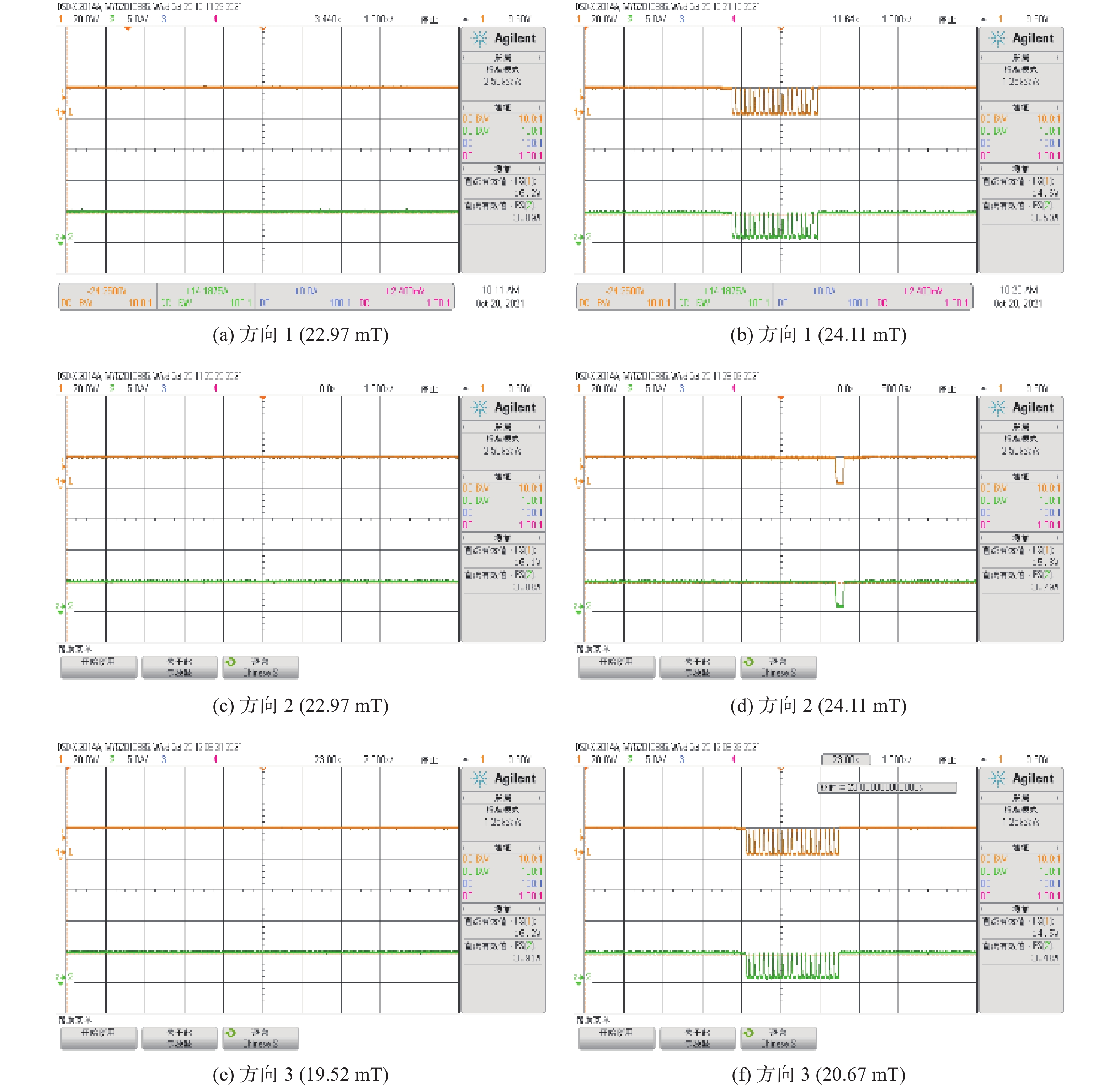
      Figure 16.  Characteristic output of switch power supply applying magnetic fields in different directions

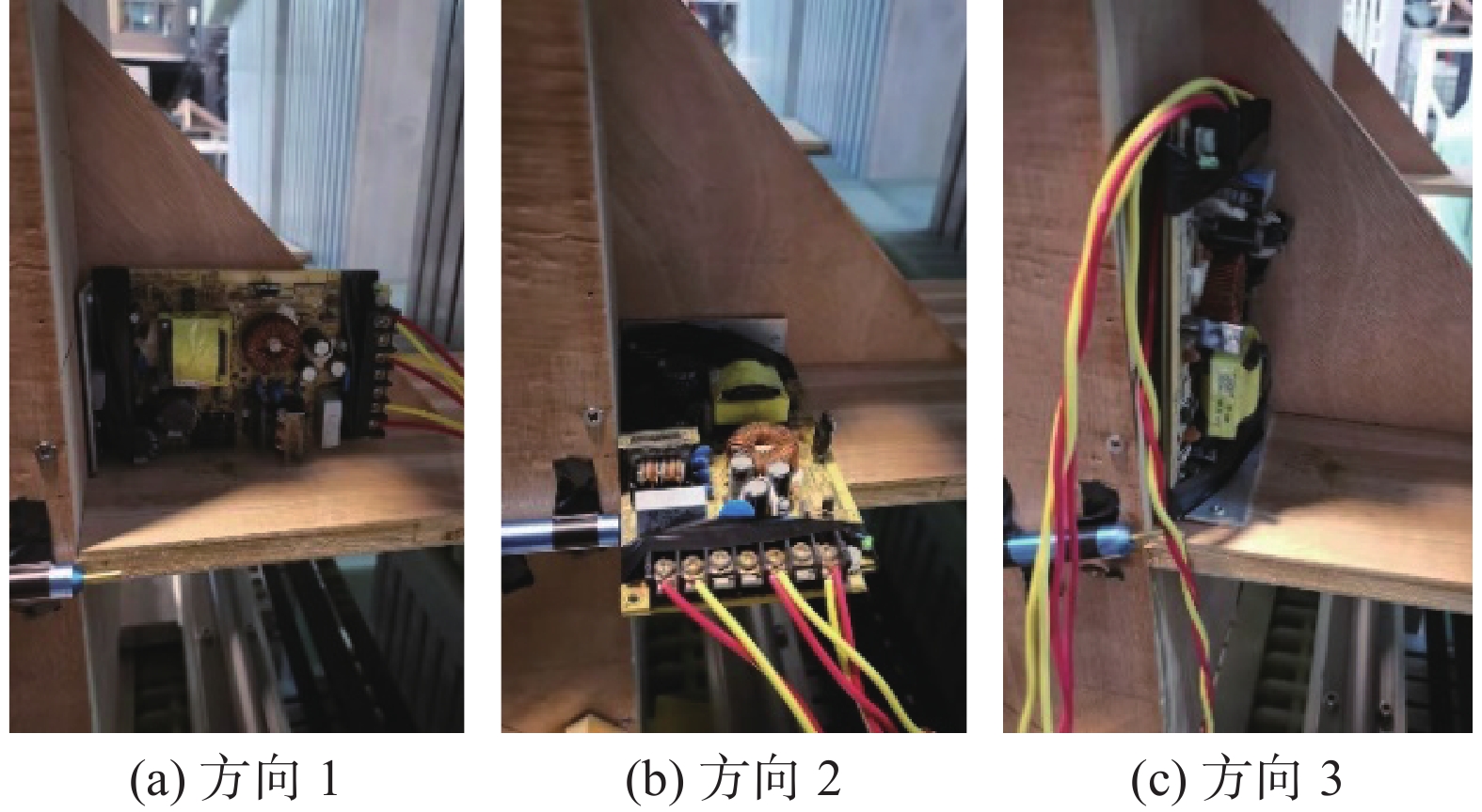
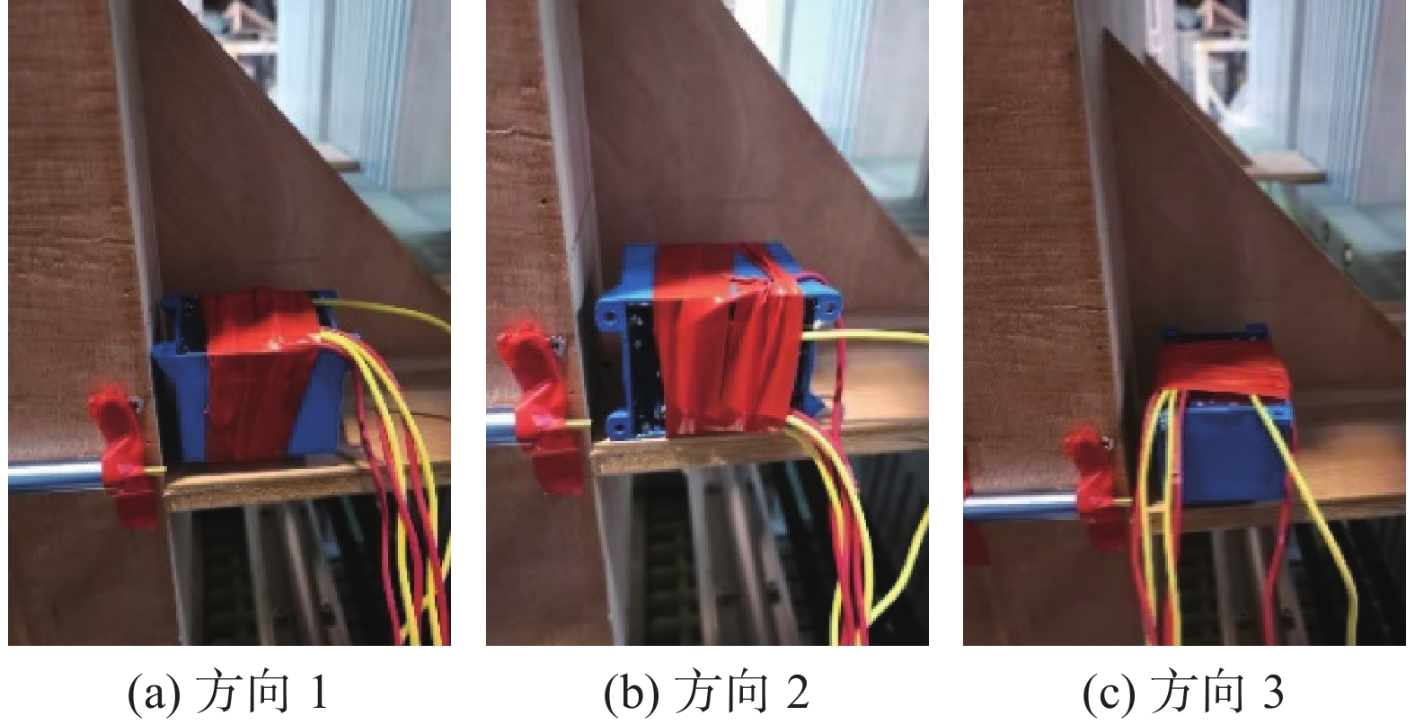
      同样针对输出12 V变压器进行空间磁场抗扰度测试,测试平台如图17所示。在变压器三个方向不断施加磁场,直至开关电源输出特性发生变化,如图18所示。以方向1为例,将外磁场从0 mT开始不断的呈阶梯式上升,测试变压器的输出特性,可以看出随着磁场值的不断上升,输出电流电压不断降低,其他两个方向具有类似的特性。

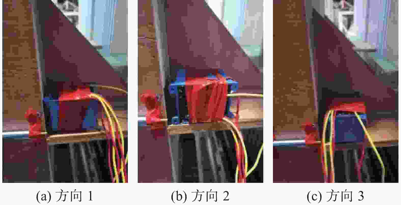
      Figure 17.  Transformers located in different magnetic field directions

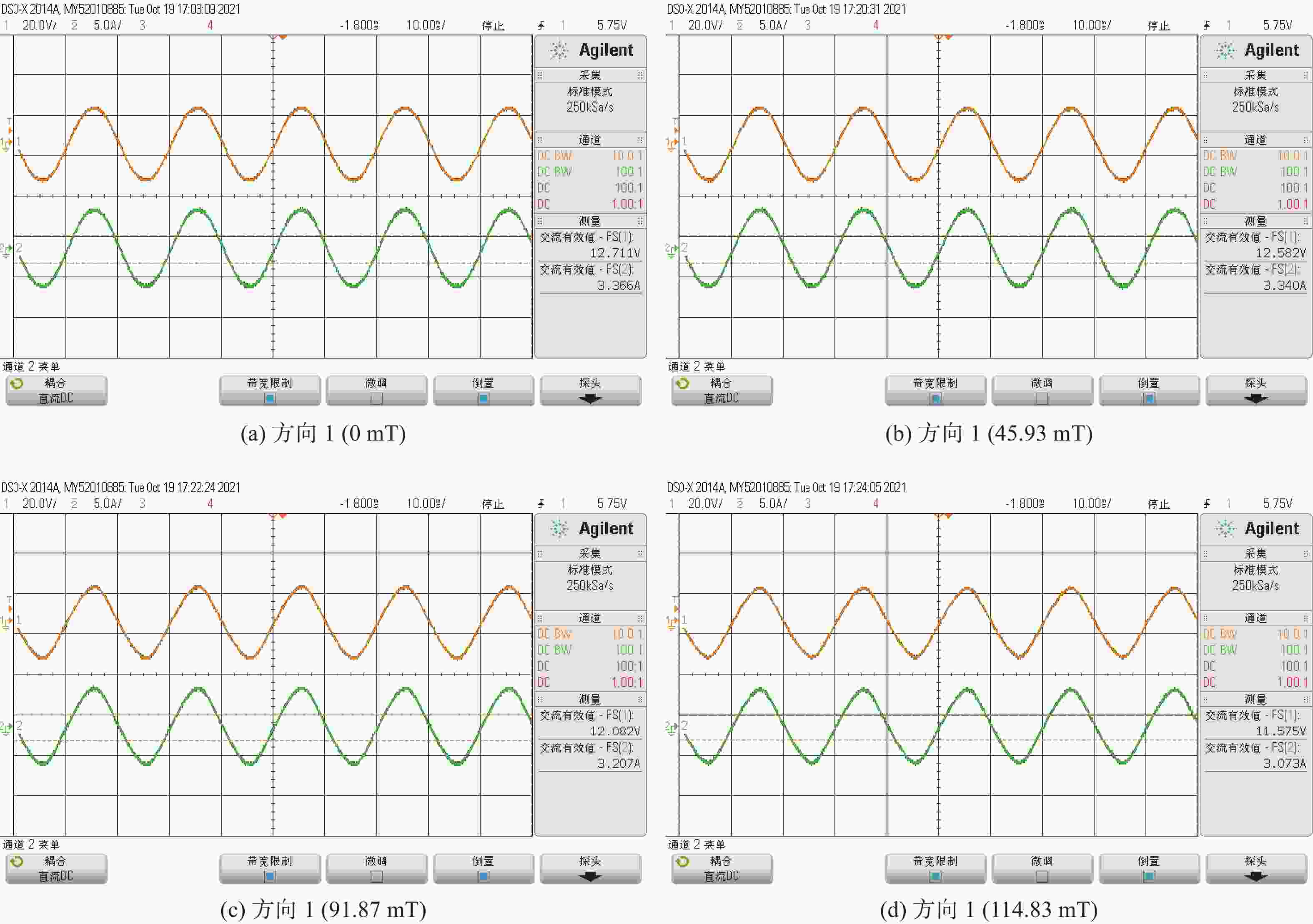
      Figure 18.  Characteristic output of magnetic field applied in direction 1 of transformer

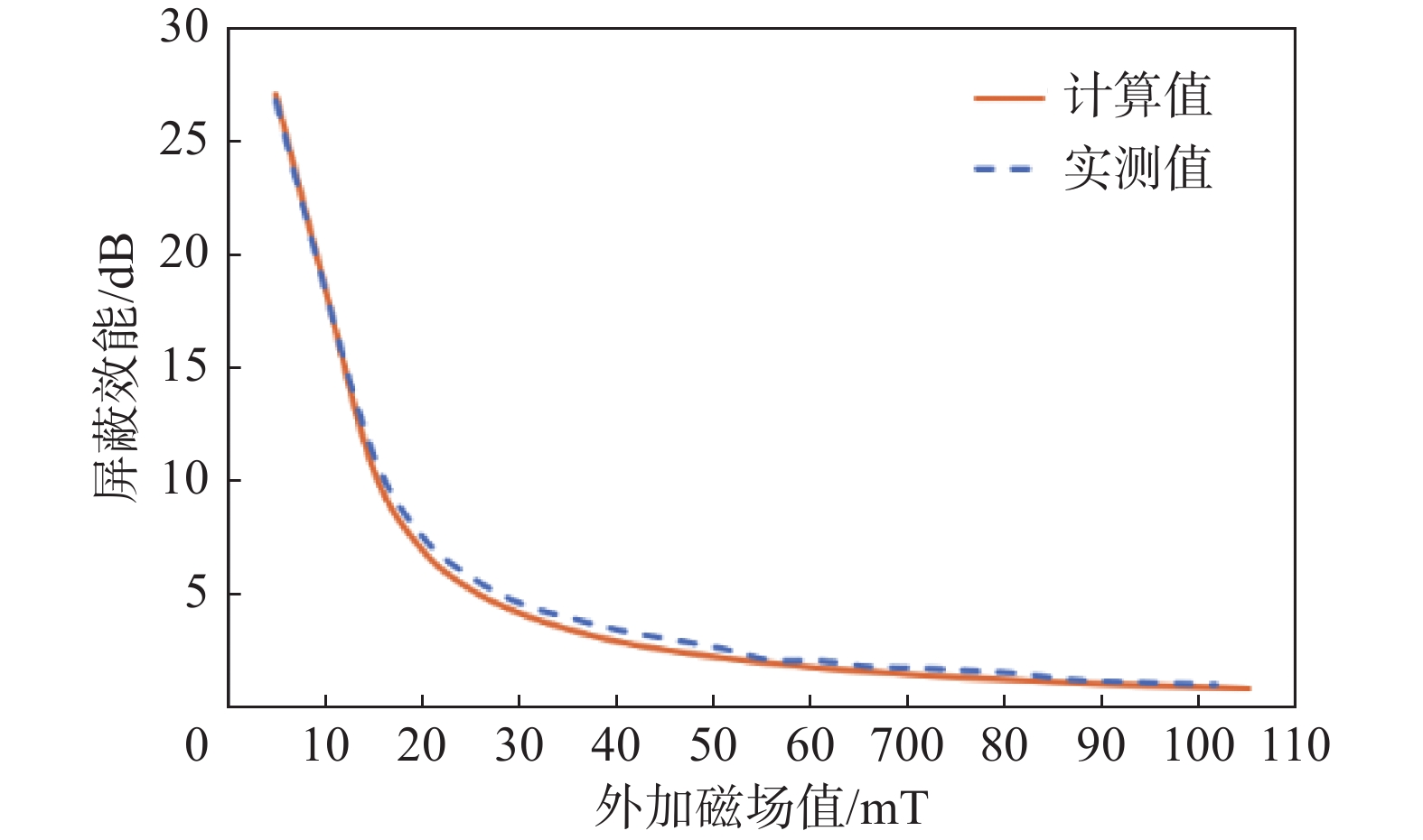
    • 测试一个硅钢材质的机柜尺寸100 mm×100 mm×100 mm(厚度5 mm),在测量系统中间磁场均匀区域三维探针,测量磁场随电流变化情况,再将机柜放置在磁场均匀区域,同一个点(机柜内部)测量磁场随电流变化,测量结果如图19所示。可以看出硅钢材质机柜对于稳态磁场的屏蔽效果,在磁场值较低时较好,随着外加磁场值的增大,屏蔽效能变差,主要由于硅钢材质存在磁饱和效应,磁场越大效果越差。同时计算值与实测值基本一致,误差最大为0.85%,验证了结果的正确性。

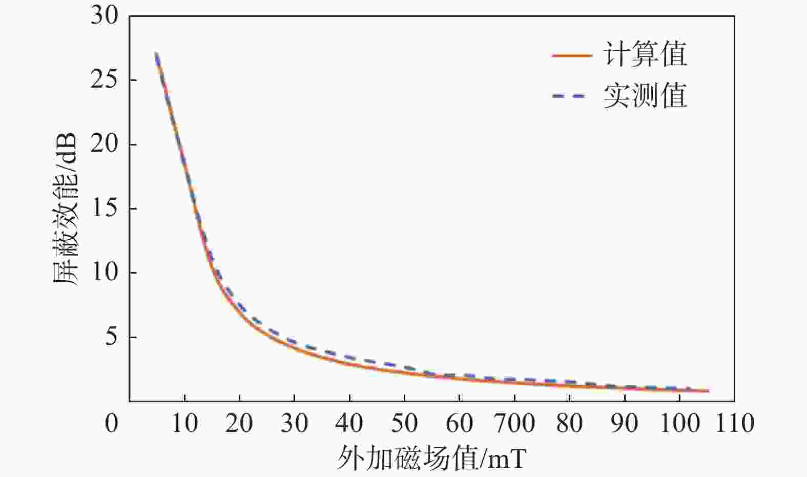
      Figure 19.  Comparison between calculated and measured shielding effectiveness of silicon steel cabinets of transformer located in different magnetic field directions

    • 关于外加磁场对磁性器件的影响及复杂电磁环境下的磁场屏蔽特点的研究,可以得出以下结论:

      1)外加磁场显著影响磁性器件特性:研究表明,外加磁场对磁性器件如开关电源和电子变压器的损耗构成具有显著影响。不同方向的磁场对损耗的影响存在差异,这主要源于磁场叠加产生的饱和效应。因此在磁性器件设计和应用时需充分考虑外界磁场的方向和强度。

      2)强磁场下磁性器件性能降低:实验结果表明,随着外磁场的增强,磁性器件的输出特性逐渐降低,甚至可能失效。这表明强磁场环境对磁性器件的性能具有负面影响,需要采取相应的磁场屏蔽措施。

      3)材料选择对磁场屏蔽效能至关重要:研究发现,不同材料如铝材和铁材在稳态和瞬态屏蔽效应中展现出不同的特点。正确选择和使用屏蔽材料,可以显著提高磁场屏蔽效果,保护磁性器件免受外界磁场干扰。

      4)计算方法在磁场屏蔽特性研究中具有准确性:通过稳态磁场测试系统对硅钢机柜进行的测试,验证了我们在磁场屏蔽特性研究中的计算方法的准确性。这为今后进一步研究和优化磁场屏蔽技术提供了有力支撑。

      综上所述,外加磁场对磁性器件的影响及复杂电磁环境下的磁场屏蔽特点是一个复杂而重要的研究领域。通过深入研究和优化设计,可以更好地应对外界磁场对磁性器件的干扰,提高其在各种环境下的性能表现。

Reference (23)

Catalog

    /

    DownLoad:  Full-Size Img  PowerPoint
    Return
    Return