
-
在“双碳”背景下,我国新型电力系统正在加速向绿色低碳转型,电力系统发电结构中新能源所占比重逐年攀升,其中,光伏和风电装机容量已跃居世界首位[1]。电力脱碳以高渗透型新能源并网为主,但是,这种不可控能源内在间歇性与随机性会影响电网电能质量、降低电网系统惯量水平并造成电网调频能力降低[2-4]。一般来说,光伏电站在1 min之内的功率下降可以达到装机容量的60%,光伏发电主要是由电力电子变流装置组成,不具备惯量及一次调频能力,不会主动响应系统频率变化,从而造成电网产生严重的频率偏差[5-7]。
电池储能系统(Battery Energy Storage System,BESS)以其高控制精度、快速响应速度和高度的灵活性而被认为是辅助风光并网调频的优选方案。国内外众多学者已经证实了BESS参与电网调频的有效性[8-12]。文献[13]探讨了在不同光伏并网场景中,电池储能系统(BESS)如何影响大型光伏并网电网系统的频率稳定性。文献[14]构建了一种光储(Photovoltaic-Energy Storage,PV-ES)系统的模型,该模型能够让逆变器的空闲容量参与到系统的调频和调峰过程中。文献[15]介绍了一种结合荷电状态(State Of Charge,SOC)和频率偏差的储能参与电网一次调频的控制方法。文献[16]针对电池储能系统提出了一种自适应充电状态(SOC)恢复策略的下垂型控制策略。文献[17]利用均值法,提出了一种适合高渗透可再生能源电网系统快速调频的储能容量分配方法。文献[18]构建了储能系统参与一次调频的区域电网等效模型。
但是,仅仅依赖电池储能来提供电网调频服务会导致较高的成本[19-20]。此外,可再生能源发电的瞬时变化或负载功率的波动可能会使电池频繁充电/放电,这会缩短BESS的使用寿命[21-22],从而降低系统的可靠性和经济性。学者们试图将电池与高功率密度的存储设备,譬如:超级电容器、超导磁储能、飞轮储能等[23-24],进行结合。与传统的电池储能方法相比,后者具有更高的功率密度和更快的动态响应,它不仅可以完成高频服务的调节信号,从而降低电池储能的压力,还能在最大程度上减少电池的尺寸和应力水平。因此,它们有能力在更短的时间内释放或吸收更多的能量,从而实现高频补偿。另外,超级电容频繁的充电和放电行为并不会对其使用寿命产生负面影响,实际上,它们的生命周期比电池储能高得多[25]。文献[26]采用混合储能技术参与电网辅助服务,并证实其不仅具有更优的经济效益,还具备更稳定的调频性能。文献[27]介绍了一种基于电池-超级电容混合储能系统参与光伏并网的自适应学习控制策略。文献[28]提出了一种飞轮和锂电池联合的混合储能参与光伏并网的一次调频控制模型,从而增强了光伏系统的一次调频性能。
上述现有的研究主要聚焦于储能参与高渗透率新能源的并网调频适应性的研究,尽管储能拥有柔性的调节能力,并能有效地辅助新能源的并网调频,但调频的最优化问题却被忽略了。新能源的并网出力具有随机性和波动性,预测误差会随着预测时间的提前而增大,从而增加配电系统优化控制的难度。模型预测控制(Model Predictive Control,MPC)是一种在特定约束条件下能够实现最优控制的技术[29],它能较好地解决上述问题,因此,在电力系统的优化控制中,它受到了高度的重视。
在“新能源+储能”的联合并网系统运行中存在储能的荷电状态(State Of Charge,SOC)和功率备用上限等约束条件,传统的处理这些约束条件的方法效果较差,而MPC能够克服系统的不确定性,是解决这个难题的有效方法。文献[30]基于模型预测控制理论提出了一种含分布式光伏配电网的有功功率-无功功率协调控制方法,将控制过程划分成多种独立模型预测控制的多时间尺度的优化模型。文献[31]提出了一种基于MPC的风储联合参与电网一次调频的优化控制策略,提高了系统的调频性能。在文献[32]中,考虑到风电场和储能的各种约束条件,基于MPC,提出了风储联合调频策略。文献[33]以最小系统频率偏差和频率变化率的总和为目标,同时考虑到光储电站的总发电量和有功功率等约束条件,提出了一种基于MPC的光储联合调频控制方案。此外,将储能与MPC同时应用于新能源发电系统调频还可以实现经济更优化。文献[34]以自动发电控制(Automatic Generation Control,AGC)和电池储能电站(Battery Energy Storage Station,BESS)运行成本最小为目标,提出了一种基于模型预测控制(MPC)的储能控制策略。在文献[35]中,引入了基于MPC的策略,降低了微电网的运营成本。文献[36]介绍了一种结合电池和超级电容的MPC控制系统,并优化了电池储能管理系统的充放电模型。从现有的光伏并网系统模型预测控制研究中可以看出,大部分研究都集中在优化储能管理系统和系统的经济性效益,缺乏对电网频率优化的关注,稳定的电网频率是影响电力系统安全平稳定运行的关键要素之一。
因此,针对上述问题,文章提出了一个基于MPC的光-储协同调频的优化策略。首先,构建了基于MPC光储逆变并网发电仿真系统,其次,在MPC预测控制策略中,考虑了光储电站的运行条件、电池电荷状态SOC等约束条件,并以光伏电压偏差、电网电压偏差和系统频率偏差最小为目标,通过滚动优化,快速精准协同控制混合储能系统,从而稳定系统的频率。
-
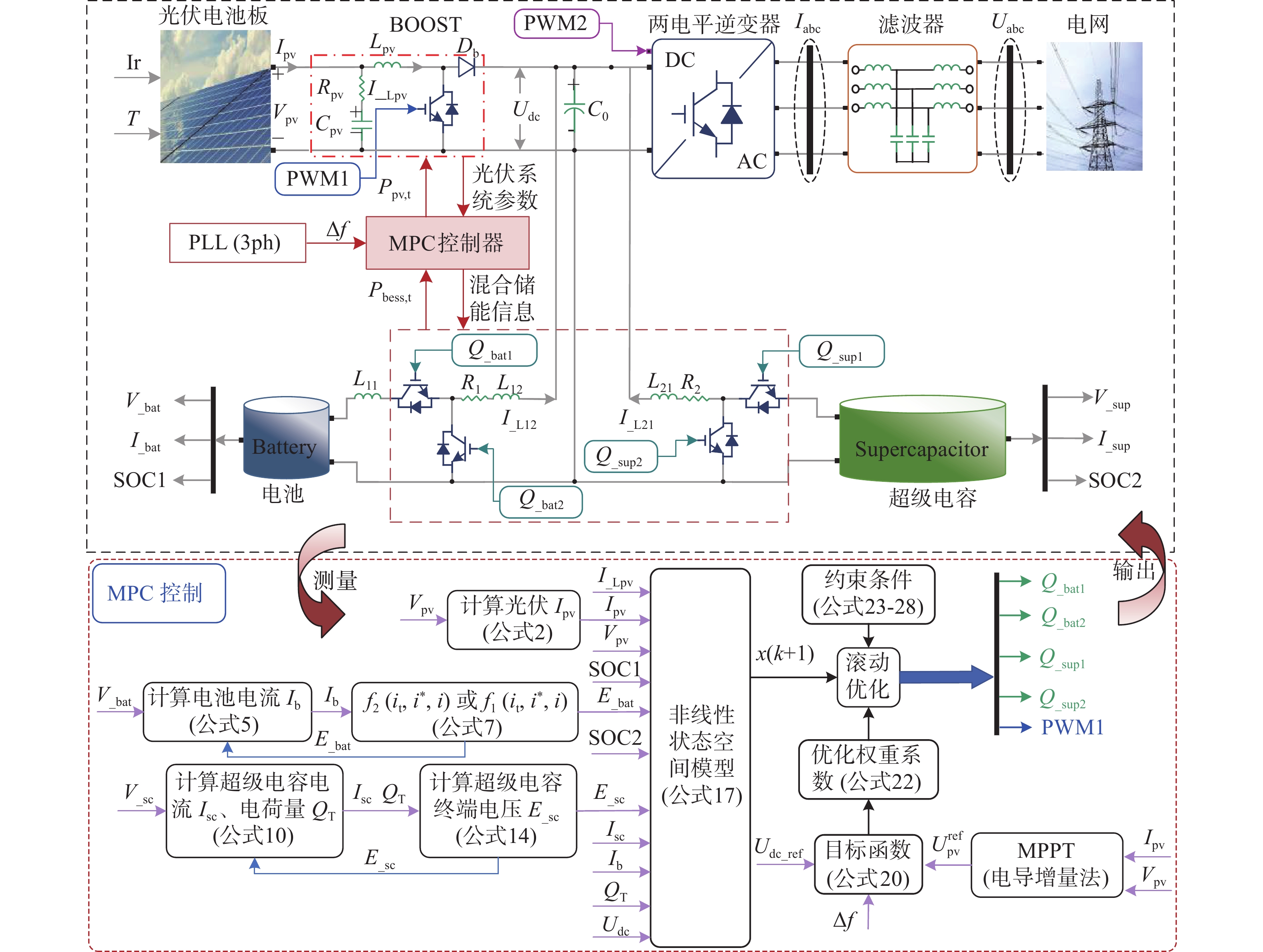
文章所研究的光-储并网系统的拓扑结构,如图1所示,该模型包含光伏列阵、升压变压器、电池储能装置、超级电容储能装置、两电平逆变器、DC-DC变换器和MPC控制器。其中升压变压器是基于DC/DC Boost电路设计的,而两个电平逆变器则是通过电流的内环与电压的外环进行控制的。

Figure 1. Topology of optical storage joint grid-connected system
光伏发电的有功出力主要受到光照和温度变化的影响,表现出非线性的特性,为实现能源最大利用,使光伏发电效率高,有必要采用最大功率点跟踪技术(Maximum Power Point Tracking,MPPT)[37],因此,文章采用常见的电导增量法(Incremental Conductance,INC)[38]来实现光伏的最大功率点跟踪。如图1所示,C0是逆变器侧直流电容,Vpv、Ipv分别是光伏侧输出电压、电流,Udc是逆变器侧直流母线电压实际值;Vacbc、Iabc分别是并网电压、电流。Cpv、Rpv为BOOST内置电容、电阻,Lpv、I_Lpv分别为BOOST内置电感和电感电流,L11、L12、R1为电池侧DC-DC变换器内置电感、电阻,L21、R2为超级电容侧DC-DC变换器内置电感、电阻。
混合储能装置DC-DC变换器的信号处理如下:
$$ \left\{\begin{array}{l}Q_{{{\_}\text{bat1}}}=(1-Q _{{{\_}\text{bat2}}})\in(0,1) \\ Q_{{{\_}\text{sup1}}}=(1-Q_{{{\_}\text {sup2}}})\in(0,1)\end{array}\right. $$ (1) -
在实际应用中,光伏阵列是通过串联或并联光伏电池来实现更高的电压和电流输出。光伏电池由一个二极管和电阻串联或并联组合而成,因此光伏阵列的非线性电压和电流关系如下所示:
$$ \left\{\begin{array}{l}I_{\mathrm{pv}}=N_{\mathrm{pa}}I_{\mathrm{pv}{'}}-N\mathrm{_{pa}}I_{\mathrm{fill}}W-\dfrac{V\mathrm{_{pv}}+I_{\mathrm{pv}}DR\mathrm{_{se}}}{DR\mathrm{_{pa}}} \\ W=\mathrm{exp}\left(\dfrac{V_{\mathrm{pv}}+I_{\mathrm{pv}}DR\mathrm{_{se}}}{\varepsilon N_{\mathrm{se}}V\mathrm{_t}}\right)-1,D=\dfrac{N_{\mathrm{se}}}{N_{\mathrm{pa}}}\end{array}\right. $$ (2) 式中:
$ I\mathrm{_{pv}} $ ——光伏输出电流(A);
$ I_{\mathrm{pv}'} $ ——光伏电流(A);
$ I\mathrm{_{fill}} $ ——饱和电流(A);
$ V\mathrm{_{pv}} $ ——光伏电压(V);
$ V\mathrm{_t} $ ——热电压(V);
$\varepsilon $ ——二极管理想因子;
${R_{{\text{se}}}}$、${R_{{\text{pa}}}}$ ——光伏串联和并联电阻值(Ω);
$ N\mathrm{_{pa}} $、$ N\mathrm{_{se}} $ ——光伏阵列电池串联和并联数量。
$ I_{\mathrm{pv}'} $,$ I\mathrm{_{fill}} $,$ V_{\mathrm{t}} $受温度T和光照强度Ir的影响,它们之间的关系式如下:
$$ \left\{ \begin{split} &{V_{\text{t}}} = \dfrac{{{N_{{\text{se}}}}kT}}{q} \\& I' = \dfrac{{{I_\text{scc}}}}{{\exp \left( {\dfrac{{{V_{{\text{ocv}}}}}}{{\varepsilon {V_{\text{t}}}{N_{{\text{se}}}}}}} \right) - 1}} \\& {I_{{\text{fill}}}} = I'{\left( {\dfrac{T}{{{T_{\text{n}}}}}} \right)^3}\exp \left\{ {\dfrac{{q{E_{{\text{bge}}}}}}{{k\varepsilon }}\left( {\dfrac{1}{{{T_{\text{n}}}}} - \dfrac{1}{T}} \right)} \right\} \\& {I_{{\text{ph}}}} = \dfrac{{\text{Ir}}}{{1\;000}}({I_\text{scc}} + {\vartheta _i}(T - {T_{\text{n}}})) \end{split} \right. $$ (3) 式中:
$ I_{\mathrm{scc}} $ ——短路电流(A);
$ {V_{{\text{ocv}}}} $ ——光伏PV的开路电压(V);
$ {T_{\text{n}}} $ ——额定温度(K);
$ {E_{{\text{bge}}}} $ ——半导体的带隙能量(J);
$ {\vartheta _i} $ ——温度系数(ppm/K);
$ k $ ——玻尔兹曼常数,1.380649×10−23J/K;
$ q $ ——电子电荷(C)。
光-储并网系统中光伏升压变压器采用BOOST拓补结构,如图1所示,根据KVL和KCL可得:
$$ \left\{ \begin{gathered} {V_{{\text{pv}}}} = {L_{{\text{pv}}}}\dfrac{{\text{d}{I_{\_{\text{Lpv}}}}}}{{\text{d}t}} + (1 - {D_\text{PWM1}}){U_{{\text{dc}}}} \\ {I_{{\text{pv}}}} = {C_{{\text{pv}}}}\dfrac{{\text{d}{V_{{\text{pv}}}}}}{{\text{d}t}} + {I_{\_{\text{Lpv}}}} \\ \end{gathered} \right. $$ (4) 式中:
$ {V_{{\text{pv}}}} $ ——光伏输出电压(V);
$ {L_{{\text{pv}}}} $ ——BOOST电路升压电感(H);
$ {I_{\_{\text{Lpv}}}} $ ——流过升压电感的电流(A);
$ {C_{{\text{pv}}}} $ ——光伏侧电容(F);
$ {U_{{\text{dc}}}} $ ——直流侧电压(V);
$ D\mathrm{_{PWM1}} $ ——DC/DC Boost电路中IGBT/Diode控制输入信号,即占空比,$ D\mathrm{_{PWM1}}(t)\in(0,1) $。
-
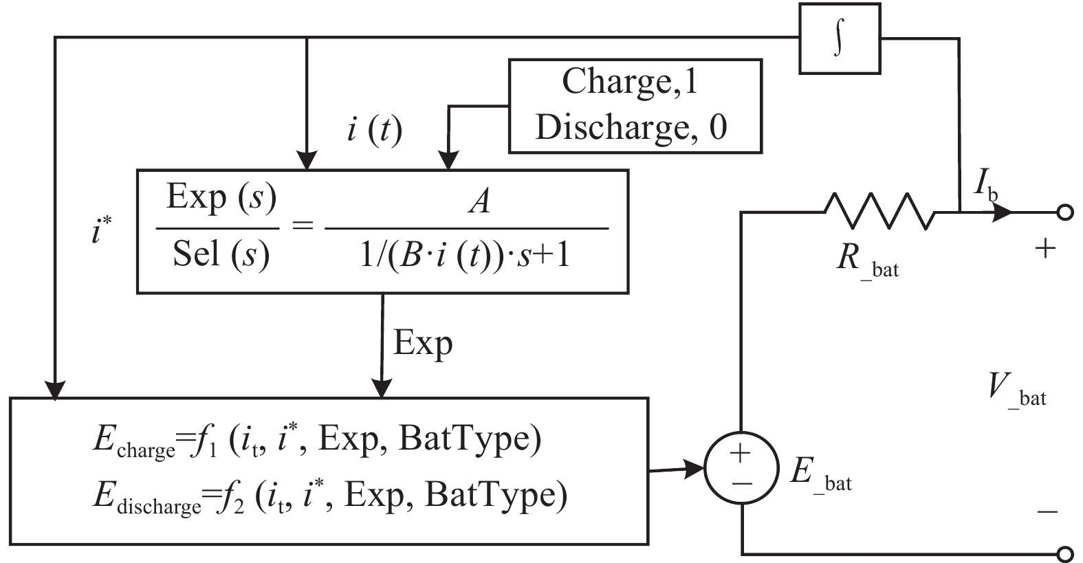
文章构建的光-储并网系统中使用了电池-超级电容混合储能,其中,电池选用最常见的锂离子电池,其等效电路模型是基于simulink的Battery模块,如图2所示,这是锂离子电池的等效电路模型,锂离子电池由受控电压E_bat和内部电阻R_bat串联而成。

Figure 2. Lithium-ion battery equivalent circuit
参数名 参数设定 参数名 参数设定 Cpv/F 1×10⁻³ C0/F 5494.374×10−4 Rpv/Ω 1×10⁻⁶ L21/H 0.3×10⁻³ Lpv/H 4.3244×10⁻² R2/Ω 0.05 L11/H 1.5×10⁻³ R1/Ω 0.05 L12/H 0.355×10⁻³ - - Table 1. Parameter setting of optical storage joint grid-connected system
电池终端电压V_bat和电池电荷状态SOC1由电池内部电流Ib决定,它们之间的关系式如下:
$$ \begin{gathered}V_{\_{\text{bat}}}=E_{\_{\text{bat}}}-R_{\_{\text{bat}}}I_b\text{ },\text{}i_\text{t}(t)=\int_0^tI_{\mathrm{b}}(t)\mathrm{d}t \\ \mathrm{SOC}1=100\left(1-\dfrac{1}{Q}\int_0^ti(t)\mathrm{d}t\right) \\ \end{gathered} $$ (5) 式中:
Q——最大电池容量(Ah)。
电池电荷状态SOC1的关系式可以转换为:
$$ \frac{\mathrm{dSOC}1}{\mathrm{d}t}=100-\frac{100(E_\mathrm{\_{bat}}-R\mathrm{_{all}}I_{\mathrm{b}}-U\mathrm{_{dc}})}{QR_{\mathrm{all}}} $$ (6) 式中,$ R\mathrm{_{all}}=R_\mathrm{\_bat}+R_1 $,它受控电压E_bat受电池的充电和放电模式影响,其表达式如下:
$$ \left\{ \begin{split} &{\mathrm{Charge}}({i^*} < 0): \\& {\text{ }}{f_1}({i_{\mathrm{t}}},{i^ * },i) = {E_{\mathrm{0}}} - \dfrac{{KQ{i^ * }}}{{{i_{\mathrm{t}}} + 0.1Q}} - \dfrac{{KQ{i_{\mathrm{t}}}}}{{Q - {i_{\mathrm{t}}}}} + A\exp ( - B{i_{\mathrm{t}}}) \\& {\mathrm{Discharge}}({i^*} > 0): \\& {f_2}({i_{\mathrm{t}}},{i^*},i) = {E_0} - \dfrac{{KQ{i^ * }}}{{Q - {i_{\mathrm{t}}}}} - \dfrac{{KQ{i_{\mathrm{t}}}}}{{Q - {i_{\mathrm{t}}}}} + A\exp ( - B{i_{\mathrm{t}}}) \end{split} \right. $$ (7) 式中:
E0 ——开路电压(V);
K ——极化常数(V/Ah);
i ——电池电流(A);
i* ——低频电流(A);
it ——提取的容量(Ah);
A ——指数电压(V);
B ——指数容量(Ah)。
根据KVL和KCL,电池变换器的电路方程式可以写成:
$$ \left\{ \begin{split} &{E_{{\mathrm{\_bat}}}} = {R_{{\mathrm{\_bat}}}}{I_{\mathrm{b}}} + {R_1}{Q_{{\mathrm{\_bat1}}}}{I_{{\mathrm{\_L12}}}} - {L_{{\mathrm{pv}}}}\dfrac{{{\mathrm{d}}{I_{{\mathrm{\_Lpv}}}}}}{{{\mathrm{d}}t}} + {R_{{\mathrm{pv}}}}{C_{{\mathrm{pv}}}}\dfrac{{{\mathrm{d}}{V_{{\mathrm{pv}}}}}}{{{\mathrm{d}}t}} \\& {R_{{\mathrm{pv}}}}{C_{{\mathrm{pv}}}}\dfrac{{{\mathrm{d}}{V_{{\mathrm{pv}}}}}}{{{\mathrm{d}}t}} = {L_{{\mathrm{pv}}}}\dfrac{{{\mathrm{d}}{I_{{\mathrm{\_Lpv}}}}}}{{{\mathrm{d}}t}} + {R_1}{I_{{\mathrm{\_L12}}}} + {L_{12}}\dfrac{{{\mathrm{d}}{I_{{\mathrm{\_L12}}}}}}{{{\mathrm{d}}t}} + {Q_{{\mathrm{\_bat2}}}}{U_{{\mathrm{dc}}}} \\& {C_0}\dfrac{{{\mathrm{d}}{U_{{\mathrm{dc}}}}}}{{{\mathrm{d}}t}} = {I_{{\mathrm{\_L12}}}} + {I_{{\mathrm{\_Lpv}}}} \end{split} \right. $$ (8) $$ \left\{ \begin{split} &{E_{{\mathrm{\_bat}}} = {R_{{\mathrm{\_bat}}}}{I_{\mathrm{b}}} + {R_1}{Q_{{\mathrm{\_bat1}}}}{I_{{\mathrm{\_L12}}}} + {R_1}{I_{\mathrm{\_L12}}}} \\& {\text{ }} + {L_{12}}\dfrac{{{{\mathrm{d}}}{I_{{\mathrm{\_L12}}}}}}{{\mathrm{d}}t} + {Q_{{\mathrm{\_bat2}}}}{U_{{\mathrm{dc}}}}{\text{ }} \\& {C_0}\dfrac{{{\mathrm{d}}{U_{{\mathrm{dc}}}}}}{{{\mathrm{d}}t}} = {I_{{\mathrm{\_L12}}}} + {I_{{\mathrm{\_Lpv}}}} \end{split} \right. $$ (9) -
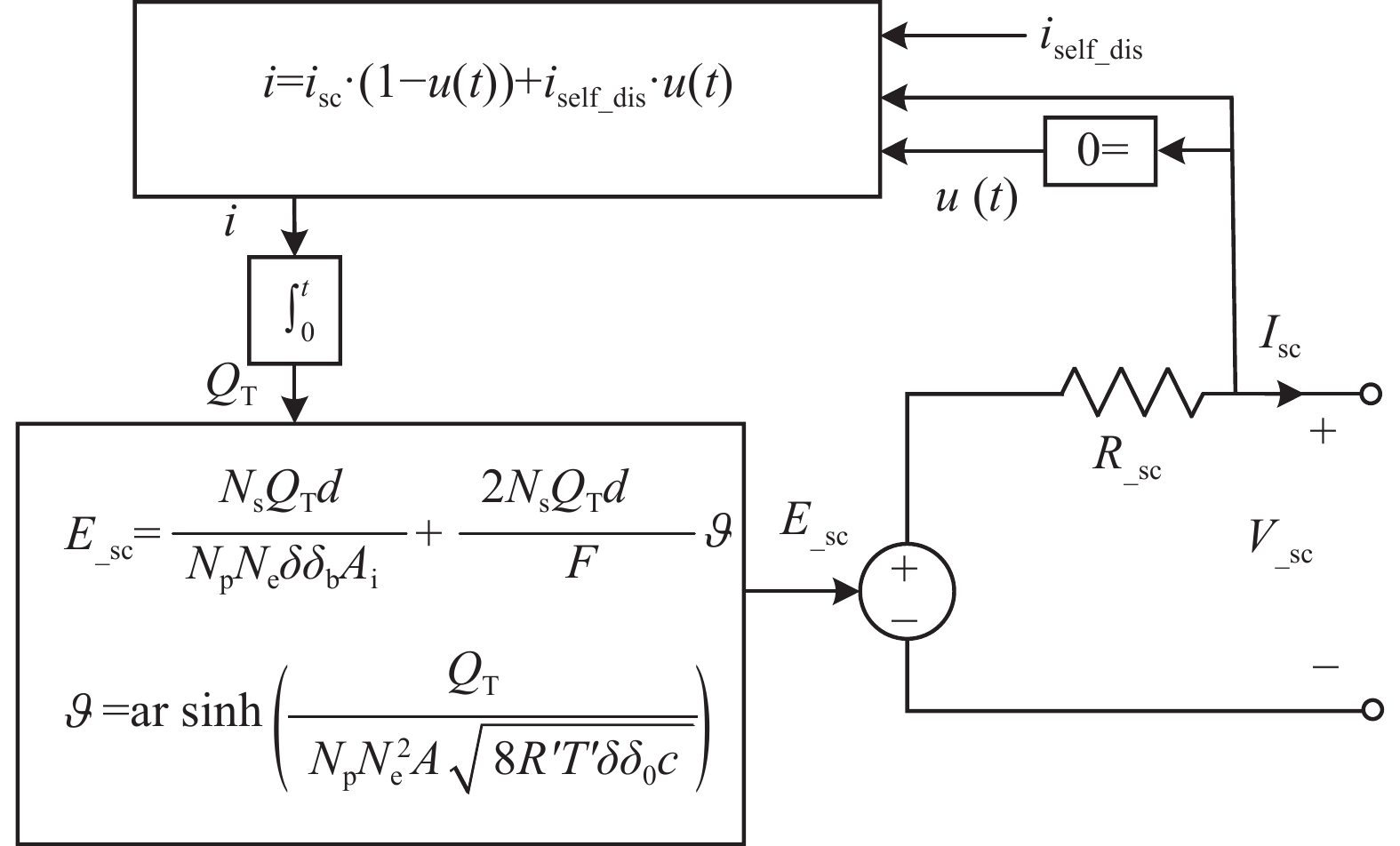
文章采用的超级电容储能等效电路模型是基于simulink的Supercapacitor模块,如图3所示,这是超级电容的等效电路模型。

Figure 3. Supercapacitor energy storage equivalent circuit
超级电容器输出电压使用Stern方程,表达式为:
$$ \left\{ \begin{split} &{V_{{\mathrm{sc}}}} = \dfrac{{{N_{\mathrm{s}}}{Q_{\mathrm{T}}}d}}{{{N_{\mathrm{P}}}{N_{\mathrm{e}}}\delta {\delta _0}{A_{\mathrm{i}}}}} + \vartheta ' - {R_{{\mathrm{sc}}}}{i_{{\mathrm{sc}}}} \\& \vartheta ' = \dfrac{{2{N_{\mathrm{e}}}{N_{\mathrm{s}}}\vartheta T'}}{F}{\mathrm{ar}}{\sin h^{ - 1}}\left( {\dfrac{{{Q_{\mathrm{T}}}}}{{{N_{\mathrm{P}}}N_{\mathrm{e}}^2{A_{\mathrm{i}}}\sqrt {8\vartheta T'\delta {\delta _0}c} }}} \right) \\& {Q_{\mathrm{T}}} = \int {{i_{{\mathrm{sc}}}}{\mathrm{d}}t} \end{split} \right. $$ (10) 式中:
E_sc ——超级电容终端电压(V);
Rsc ——总电阻(Ω);
isc ——超级电容器电流(A);
QT ——电荷量(C);
d ——分子半径(m);
$ \delta $ ——材料的介电常数(F/m);
$ {\delta _0} $ ——真空介电常数,8.854187817×10−12 F/m;
Ai ——电极和电解质之间的界面面积(m2);
Ne ——电极层数;
Ns ——并联超级电容器的数量;
NP ——并联超级电容器的数量;
$ \vartheta $ ——理想气体常数,8.314 J/(mol·K);
$ T' $ ——工作温度(K);
F ——法拉第常数,96485.3383±0.0083 C/mol;
$ c $ ——摩尔浓度(mol/L)。
当超级电容处于自放电状态时,isc=0,QT的表达式如下所示:
$$ {Q}_{{\mathrm{T}}}={\displaystyle \int i{}_{{\mathrm{self\_dis}}}{\mathrm{d}}t}\text{,}\text{ }({i}_{{\mathrm{sc}}}=0) $$ (11) 式中:
$ i{}_{{\mathrm{self\_dis}}} $——自放电电流(A),它在不同时间段,有不同的输出值,其表达式如下:
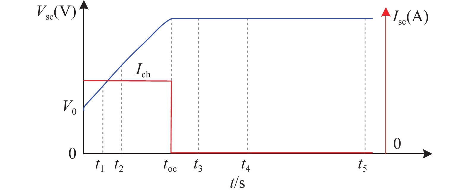
$$ i{}_{{\mathrm{self\_dis}}}=\left\{ {\begin{array}{l}\dfrac{{C}_{{\mathrm{T}}}{\alpha }_{1}}{1+s{R}_{{\mathrm{sc}}}{C}_{{\mathrm{T}}}}\text{ (}{\mathrm{if}}\text{ }t-{t}_{{\mathrm{oc}}}\leqslant {t}_{3})\\ \dfrac{{C}_{{\mathrm{T}}}{\alpha }_{2}}{1+s{R}_{{\mathrm{sc}}}{C}_{{\mathrm{T}}}}\text{ (}{\mathrm{if}}\text{ }{t}_{3} < t-{t}_{{\mathrm{oc}}}\leqslant {t}_{4})\\ \dfrac{{C}_{{\mathrm{T}}}{\alpha }_{3}}{1+s{R}_{{\mathrm{sc}}}{C}_{{\mathrm{T}}}}\text{ }({\mathrm{if}}\text{ }t-{t}_{{\mathrm{oc}}} > {t}_{4})\end{array}} \right. $$ (12) 式中:
CT ——超级电容器电压(V);
常数$ {\alpha _1} $、$ {\alpha _2} $和$ {\alpha _3} $ ——超级电容电压在时间间隔(toc,t3)、(t3,t4)和(t4,t5)期间的变化率,如图4所示。

Figure 4. Supercapacitor voltage charge and discharge characteristics
充满电的超级电容器的电荷状态SOC2为100%,而空的超级电容机的SOC为0%。SOC2表达式如下:
$$ {\mathrm{SOC2}} = \dfrac{{{Q_{{\mathrm{init}}}} - \int_0^{{t}} {i(\tau ){\mathrm{d}}\tau } }}{{{Q_{\mathrm{T}}}}} \times 100 $$ (13) 式中:
Qinit——初始电荷量(C)。
超级电容电荷状态SOC2的表达式可以转换为:
$$ \frac{{{\text{d}}{\mathrm{SOC2}}}}{{{{\mathrm{d}}t}}} = \frac{{100{Q_{{\mathrm{init}}}}}}{{{Q_{\mathrm{T}}}}} - \frac{{100({E_{{\mathrm{\_sc}}}} - {R_2}{I_{{\mathrm{sc}}}} - {U_{{\mathrm{dc}}}})}}{{Q{}_{\mathrm{T}} \cdot ({R_{{\mathrm{\_sc}}}} + {R_2})}} $$ (14) 根据KVL和KCL,超级电容变换器的电路方程式可以写成:
$$ \left\{ \begin{split} &{E_{{\mathrm{\_sc}}}} = {R_{{\mathrm{\_sc}}}}{I_{{\mathrm{sc}}}} + {R_2}{Q_{{\mathrm{\_\sup 1}}}}{I_{{\mathrm{\_L21}}}} - {L_{{\mathrm{pv}}}}\dfrac{{{\mathrm{d}}{I_{{\mathrm{\_Lpv}}}}}}{{{\mathrm{d}}t}} + {R_{{\mathrm{pv}}}}{C_{{\mathrm{pv}}}}\dfrac{{{\mathrm{d}}{V_{{\mathrm{pv}}}}}}{{{\mathrm{d}}t}} \\& {R_{{\mathrm{pv}}}}{C_{{\mathrm{pv}}}}\dfrac{{{\mathrm{d}}{V_{{\mathrm{pv}}}}}}{{{\mathrm{d}}t}} = {L_{{\mathrm{pv}}}}\dfrac{{{\mathrm{d}}{I_{{\mathrm{\_Lpv}}}}}}{{{\mathrm{d}}t}} + {R_2}{I_{{\mathrm{\_L21}}}} + {L_{21}}\dfrac{{{\mathrm{d}}{I_{{\mathrm{\_L21}}}}}}{{{\mathrm{d}}t}} + {Q_{{\mathrm{\_\sup 2}}}}{U_{{\mathrm{dc}}}} \\& {C_0}\dfrac{{{\mathrm{d}}{U_{{\mathrm{dc}}}}}}{{{\mathrm{d}}t}} = {I_{{\mathrm{\_L21}}}} - {I_{{\mathrm{\_Lpv}}}} \end{split} \right. $$ (15) 化简上式子可得:
$$ \left\{ \begin{split} &{E_{{\mathrm{\_sc}}}} = {R_{{\mathrm{\_sc}}}}{I_{{\mathrm{sc}}}} + {R_2}{Q_{{\mathrm{\_\sup 1}}}}{I_{{\mathrm{\_L21}}}} + {R_2}{I_{{\mathrm{\_L21}}}} \\& {\text{ }} + {L_{21}}\dfrac{{{\mathrm{d}}{I_{\_L2{\mathrm{}}1}}}}{{{\mathrm{d}}t}} + {Q_{{\mathrm{\_\sup 2}}}}{U_{{\mathrm{dc}}}} \\& {C_0}\dfrac{{{\mathrm{d}}{U_{{\mathrm{dc}}}}}}{{{\mathrm{d}}t}} = {I_{{\mathrm{\_L21}}}} - {I_{{\mathrm{\_Lpv}}}} \end{split} \right. $$ (16) 混合储能参数的设置如表2所示。
电池参数 参数值 超级电容参数 参数值 极化常数K 0.28×10⁻³ V/Ah 额定电容Csc 99.5 F 指数电压A 1.28 V 等效电阻R_sc 8.9×10⁻³ Ohms 指数容量B 1.3 Ah 摩尔浓度c 1/(8NAr3) Table 2. Hybrid energy storage parameter setting
-
根据公式(4)、公式(6)、公式(9)、公式(14)、公式(16)构建文章的系统状态空间方程:
$$ \begin{split} &{{\dot x}_1} = \frac{{{x_2}}}{{{L_{{\mathrm{pv}}}}}} - \frac{{(1 - {D_{{\mathrm{PWM1}}}}){U_{{\mathrm{dc}}}}}}{{{L_{{\mathrm{pv}}}}}}\\& {{\dot x}_2} = \frac{{{I_{{\mathrm{pv}}}}}}{{{C_{{\mathrm{pv}}}}}} - \frac{{{x_1}}}{{C{}_{{\mathrm{pv}}}}} \\& {{\dot x}_3} = \frac{{{E_{{\mathrm{\_bat}}}} - {R_{{\mathrm{\_bat}}}}{I_{\mathrm{b}}} - {Q_{{\mathrm{\_bat1}}}}{U_{{\mathrm{dc}}}} - ({Q_{{\mathrm{\_bat2}}}} + 1){R_1}{x_3}}}{{{L_{12}}}} \\& {{\dot x}_4} = \frac{{E{}_{{\mathrm{\_sc}}} - {R_{{\mathrm{\_sc}}}}{I_{{\mathrm{sc}}}} - {Q_{{\mathrm{\_\sup 1}}}}{U_{{\mathrm{dc}}}} - ({Q_{{\mathrm{\_\sup 2}}}} + 1){R_2}{x_4}}}{{{L_{21}}}} \\& {{\dot x}_5} = 100 - \frac{{100\left[ {{E_{{\mathrm{\_bat}}}} - ({R_{{\mathrm{\_bat}}}} + {R_1}){I_{\mathrm{b}}} - {U_{{\mathrm{dc}}}}} \right]}}{{Q({R_{{\mathrm{\_bat}}}} + {R_1})}} \\& {{\dot x}_6} = \frac{{100{Q_{{\mathrm{init}}}}}}{{{Q_{\mathrm{T}}}}} - \frac{{100({E_{{\mathrm{\_sc}}}} - {R_2}{I_{{\mathrm{sc}}}} - {U_{{\mathrm{dc}}}})}}{{{Q_{\mathrm{T}}}({R_{{\mathrm{\_sc}}}} + {R_2})}} \\& 2{x_1} = {x_3} + {x_4} \end{split} $$ (17) 式中,x=[x1,x2,x3,x4,x5,x6]T=[I_LPV,Vpv,I_L12,I_L21,SOC1,SOC2]T。
-
文章研究提出了一种基于MPC的混合储能参与光伏并网调频控制策略,混合储能采用电池储能和超级电容储能,其中,超级电容储能主要负责补偿高频的功率变化,电池储能主要负责补偿低频的功率变化。
MPC控制的核心思想是:在控制时域t时刻,模型预测会通过初始状态来求解系统的动态模型从而预测未来[t,t+k]的状态,其中k是采样步长。基于这些预测的状态和反馈数据,在给定的范围内,通过目标函数和约束条件滚动优化生成控制序列。此时控制序列将被列为下一个控制对象,在t+1时刻,循环上述操作,直至结束。对于光伏并网系统而言,温度和太阳辐照是不可控的环境因素,模型预测控制器需要对这些非确定性参数值进行预测,以便求解动态模型,MPC方程可以描述为:
$$ x(k + 1) = f[x(k),u(k),\omega (k)],{\text{ }}x(0) = {x_0} $$ (18) 式中:
x0 ——初始状态;
x(k)、u(k)、ω(k) ——状态变量、控制输入和环境参数。
-
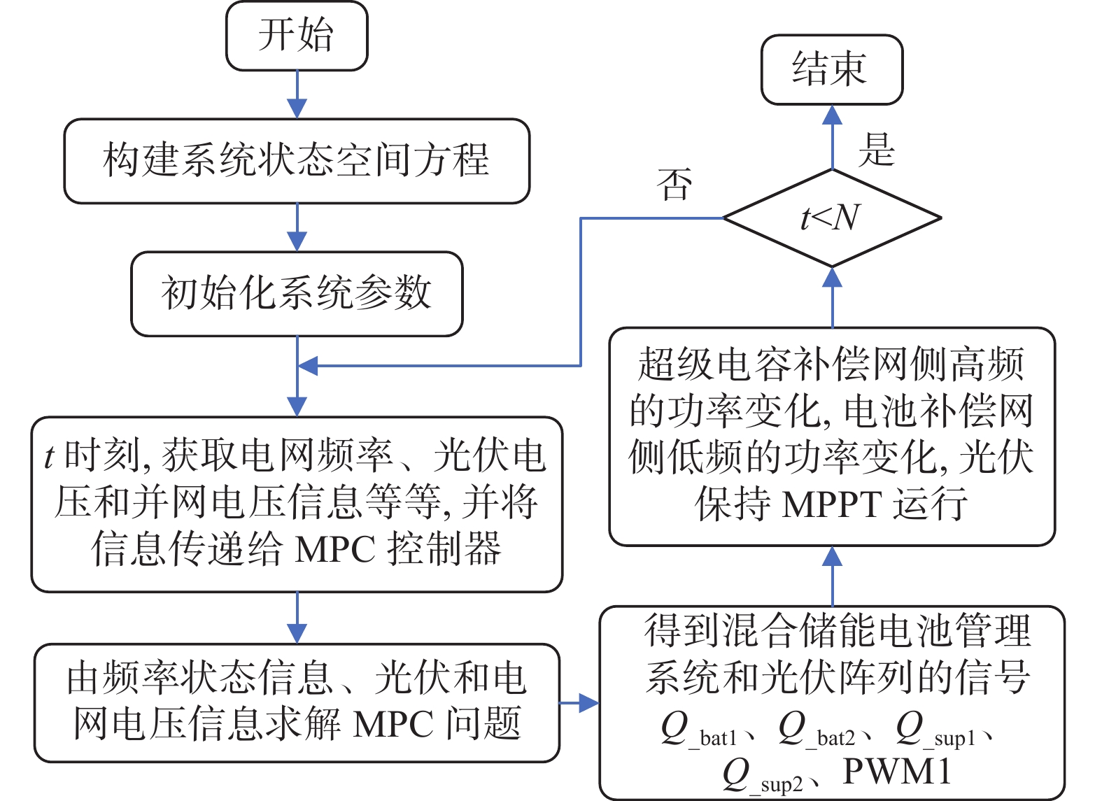
如图5所示,为基于MPC的光-储协同调频控制流程。

Figure 5. Optical-storage network FM control flow based on MPC
1)首先建立系统状态空间方程,并对系统参数进行初始化。
2)其次获取该时刻电网频率、光伏电压和并网电压等相关信息,并将这些数据传送至MPC控制器。
3)接着依据目标函数和优化权重系数方程,MPC控制器将获取的状态信息进行求解。
4)继而得到混合储能电池管理系统以及光伏阵列的控制序列。
5)然后MPC控制器会发送信号,使得超级电容能够补偿网侧高频的功率变化,而电池则可以补偿网侧低频的功率变化,同时确保光伏系统维持MPPT的运行状态。
6)最后判断是否完成整个控制时域。若否,那么继续更新系统t=t+1时刻的状态信息,并返回步骤2),若是,则结束控制流程。
-
文章研究的MPC控制器的目标是当环境参数(光照强度、环境温度)发生变化时候,通过控制混合储能管理系统中变换器的占空比信号,使混合储能管理系统能够及时补偿系统高、低频变化功率分量,从而降低系统频率的波动,提高系统稳定性。目标函数的表达式为:
$$ {J_{\min }} =\displaystyle \sum\limits_{k = 0}^{N - 1} {F[x(k),u(k)]} $$ (19) 式中:
$ {J_{\min }} $——成本函数。
函数$ F( \cdot ) $表达式如下:
$$ \begin{split} &F[x(k),u(k)] = \xi ||{U_{{\mathrm{pv}}}}(k) - U_{{\mathrm{{\mathrm{pv}}}}}^{{\mathrm{ref}}}|| + \rho ||\Delta f(k) - \Delta {f_{{\mathrm{thres}}}}||+\\& \tau ||{U_{{\mathrm{dc}}}}(k) - U_{{\mathrm{dc}}}^{{\mathrm{ref}}}||{\text{ }} \end{split} $$ (20) 式中:
$$ \Delta f(k + 1) = f(k) - {f_0}{\text{ }}\forall k \in [0,1,...,N - 1] \text{;} $$ $ U_{{\mathrm{pv}}}^{{\mathrm{ref}}} $ ——光伏电压参考值(V);
$ U_{{\mathrm{dc}}}^{{\mathrm{ref}}} $ ——并网电压参考值(V);
$ \Delta {f_{{\mathrm{thres}}}} $ ——设定的频率偏差阈值,文章取0.02;
$ \xi $、$ \rho $、$ \tau $ ——对应每个函数项的加权因子,当$ ||\Delta f(k) - \Delta {f_{{\mathrm{thres}}}}|| \leqslant 0{\text{ }} $时,$ \rho $=0。
控制器在控制输入的变化量最小的情况下,控制器每个时间步长k中解决预测范围中的优化问题。优化问题的第一个目标是保证光伏电压Upv能够跟踪由电导增量法获得的电压参考值$ U_{{\mathrm{pv}}}^{{\mathrm{ref}}} $;第二个目标是将频率偏差$ \Delta f $控制在设定的频率阈值范围;第三个目标是维持系统运行条件下直流母线电压稳定。
-
温度和光照强度作为光伏系统扰动量输入,首先影响的是光伏输出功率Ppv,当光伏输出功率处于稳定状态时,频率的表现较为稳定;当输出功率处于不稳定状态时,频率的表现不稳定,它们之间的关系可表示为:
$$ \left\{ {\begin{array}{l}\dfrac{{\mathrm{d}}{P}_{{\mathrm{pv}}}}{{\mathrm{d}}t}=0\text{ }\left(频率较稳定\right)\\ \dfrac{\left|{P}_{{\mathrm{pv}}}\right|}{{\mathrm{d}}t}\ne 0\text{ }\left(频率不稳定\right)\end{array}} \right. $$ (21) 加权系数的构建可以采用一次函数、二次函数、指数函数甚至复杂函数。其中,在光伏输出功率偏差较大时,指数函数对加权系数的调整具有更快的速度,当系统受扰动时,能够快速响应调频,进一步促进频率的稳定性。当光伏输出功率偏差相对较小的时候,指数函数会相应地减小,然而这种程度的减小的速度会稍微慢于一次函数和二次函数。因此,文章采用指数函数对频率偏差权重系数$ \rho $进行重构。具体设计方程如下:
$$ {\rho _o} = \rho + {k_{\mathrm{e}}}\left( {{e^{\left| {{{P'}_{{\mathrm{pv}}}}\left( k \right)} \right|}} - 1} \right) $$ (22) 式中:
$ \rho $ ——加权系数初始值;
ke ——加权调整系数。
-
在优化问题中的约束条件中,考虑了储能装置的运行条件限制、电池的电荷状态SOC以及光伏的运行条件限制。
1)储能装置运行约束[30]
$$ {L_{{\mathrm{SOC}},n,t}} + {P_{{\mathrm{cha}},n,t}}{\eta _{{\mathrm{cha}}}}\Delta T - \dfrac{{{P_{{\mathrm{dis}},n,t}}}}{{{\eta _{{\mathrm{dis}}}}}}\Delta T = {L_{{\mathrm{SOC}},n,t + \Delta T}} $$ (23) $$ \left\{ {\begin{array}{l}0.2{L}_{{}_{{\mathrm{SOC}},n}}^{\mathrm{max}}\leqslant {L}_{{\mathrm{SOC}},n,t}\leqslant 0.8{L}_{{}_{{\mathrm{SOC}}\text{,}t}}^{\mathrm{max}}\\ 0\leqslant {P}_{{\mathrm{cha}},n,t}\leqslant {P}_{{\mathrm{cha}},n,t}^{\mathrm{max}}{N}_{{\mathrm{cha}},n,t}\\ 0\leqslant {P}_{{\mathrm{dis}},n,t}\leqslant {P}_{{\mathrm{dis}},n,t}^{\mathrm{max}}{N}_{{\mathrm{dis}},n,t}\\ {N}_{{\mathrm{cha}},n,t}+{N}_{{\mathrm{dis}},n,t}\leqslant 1\end{array}} \right. $$ (24) 式中:
$ {P_{{\mathrm{cha}}\_t}} $、$ {P_{{\mathrm{dis}}\_t}} $和$ P_{{\mathrm{cha}}{\mathrm{}}\_{t}}^{\max } $、$ P_{{\mathrm{dis}}\_t}^{\max } $ ——t时刻储能设备的充、放电功率和最大充、放电功率(W);
$ {\eta _{{\mathrm{cha}}}} $、$ {\eta _{{\mathrm{dis}}}} $ ——储能设备充、放电效率;
$ {N_{{\mathrm{cha}}\_t}} $、$ {N_{{\mathrm{dis}}{\mathrm{}}\_t}} $ ——防止储能设备同时发生充、放动作的0、1控制变量;
$ L_{_{{\mathrm{SOC}}}}^{\max } $ ——储能设备的充电限值。
2)储能装置参考功率与SOC约束
文章采用锁相环(Phase Lock Loop,PLL)技术对电网的频率$ f $进行实时跟踪,依据$ f $的不同取值对逆变器的有功输出进行调控,$ {f_0} $为基准频率,取值50 Hz。
电池储能随着电网频率的偏移进行充放电,储能电池在调频状态下的参考功率与SOC的约束条件如下[14]:
$$ {P'_{{\mathrm{ess1}}}} = \left\{ {\begin{array}{*{20}{c}} { - {P_{{\mathrm{bat\_e}}}}}&{\{ \Delta f > 0.04,{\text{ }}{\mathrm{SOC}} \in ({\mathrm{SOC}}_{\min },{\mathrm{SOC}}_{\max })\} } \\ {{P_{{\mathrm{bat\_e}}}}}&{\{ \Delta f < - 0.04,{\text{ }}{\mathrm{SOC}} \in ({\mathrm{SOC}}_{\min },{\mathrm{SOC}}_{\max })\} } \end{array}} \right. $$ (25) 式中:
${P_{{\mathrm{bat\_e}}}}$ ——储能电池的额定功率(W),规定放电为正;
SOCmax、SOCmin ——90%和20%。
超级电容储能可以防止小幅高频扰动造成频率波动,超级电容储能在调频状态下的参考功率与SOC的约束条件如下:
$$ {P'_{{\mathrm{ess2}}}} = \left\{ {\begin{array}{*{20}{c}} { - {P_{{\mathrm{\sup \_e}}}}}&{\{ \Delta f > 0.06,{\mathrm{SOC}} \in ({\mathrm{SOC}}_{\min },{\mathrm{SOC}}_{\max })\} } \\ {{P_{{\mathrm{\sup \_e}}}}}&{\{ \Delta f < - 0.06,{\mathrm{SOC}} \in ({\mathrm{SOC}}_{\min },{\mathrm{SOC}}_{\max })\} } \end{array}} \right. $$ (26) 式中:
${P_{{\mathrm{\sup \_e}}}}$ ——储能电池的额定功率(W),规定放电为正。
3)光伏运行约束条件
$$ \left\{ \begin{gathered} {P_{{\mathrm{DG}},n,t}} = P_{{\mathrm{DG}},n,t}^{{\mathrm{pre}}} \\ Q_{{\mathrm{DG}},n,t}^{\min } \leqslant {Q_{{\mathrm{DG}},n,t}} \leqslant Q_{{\mathrm{DG}},n,t}^{\max } \\ Q_{{\mathrm{DG}},n,t}^{\max } = - Q_{{\mathrm{DG}},n,t}^{\min } = \sqrt {F_{{\mathrm{DG}},n}^2 - {{(P_{{\mathrm{DG}},n,t}^{{\mathrm{pre}}})}^2}} \\ \end{gathered} \right. $$ (27) 式中:
$ P_{\mathrm{DG},n,t}^{\mathrm{pre}} $ ——t时刻n节点处的光伏有功功率预测值(W);
$ Q_{\mathrm{DG},n,t}^{\max} $、$ Q_{\mathrm{DG},n,t}^{\min} $ ——t时刻n节点处光伏无功功率的上、下限制(Var);
$ F_{\mathrm{DG},n} $ ——n节点处的光伏容量(W)。
4)电压水平和电流约束条件
$$ \begin{gathered} {I_{j,t}} \leqslant I_j^{\max } \\ U_n^{\min } \leqslant {U_{n,t}} \leqslant U_n^{\max } \\ \end{gathered} $$ (28) 式中:
$ I_j^{\max } $ ——支路j的电流上限幅值(A);
$ U_n^{\max } $、$ U_n^{\min } $ ——n节点处电压上、下限幅值(V)。
-
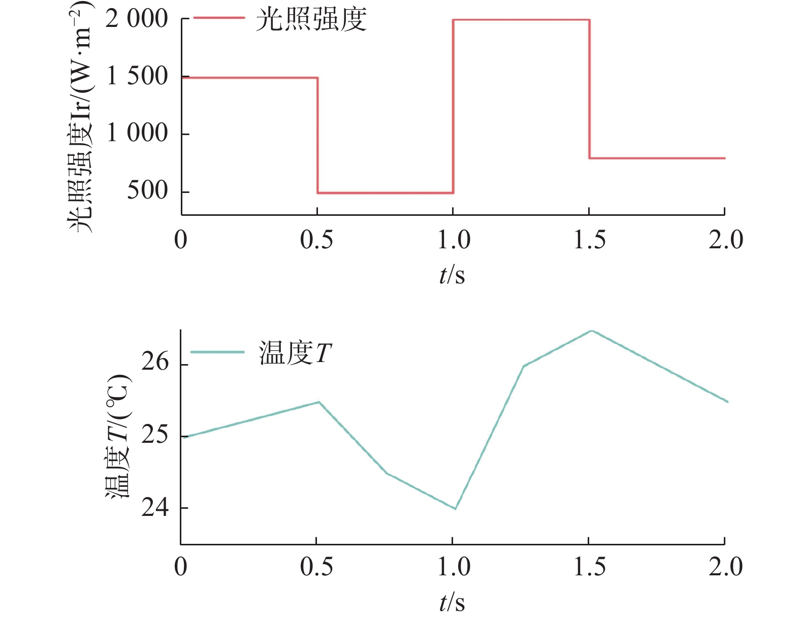
为验证文章所提出的基于MPC的光-储协同调频优化策略的可行性和有效性,在MATLAB/Simulink中建立了相应的仿真模型,并进行了实验验证。该系统光伏容量为50 MW,采用200串250并的连接方式,电池储能配置5 MW,由5套1 MW的蓄电池组成,采用5串10并的连接方式,超级电容配置10 MW,由10套1 MW的超级电容组成,采用1串10并的连接方式。光伏阵列输入光照强度和温度信号,如图6所示[14]。光照强度初始状态为1500 W/m2,直到0.5 s时刻,下降为500 W/m2,继续维持到0.5 s后,上升到2000 W/m2,直到1.5 s时刻,又下降到800 W/m2。温度初始值为25 ℃,受光照和环境影响到0.5 s时缓慢上升至25.5 ℃,0.5 s之后温度持续缓慢下降到24 ℃,1 s之后温度上升到1.5 s的26.5 ℃,最后又开始下降到2 s时刻的25.5 ℃。文章设置仿真时间为2 s。

Figure 6. PV input light intensity and temperature signal changes
-
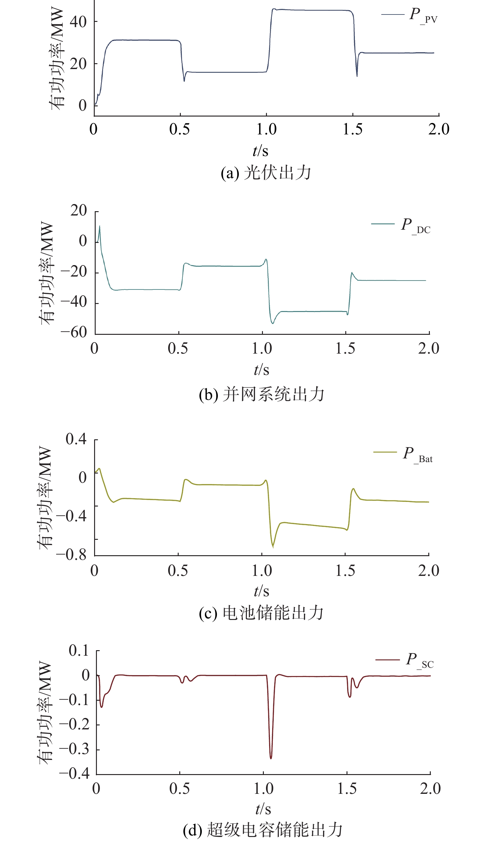
系统的出力特性情况如图7所示,P_PV、P_DC、P_Bat、P_SC依次表示为光伏出力、并网系统出力、电池储能出力、超级电容储能出力。

Figure 7. System output characteristics
受光伏光照强度和温度变化影响,光伏出力在0.5 s、1 s、1.5 s附近发生较大的波动。可见,电池储能出力较为平滑,当光伏出力增加时,电池储能充电,当光伏出力下降时,电池会进行放电。同理,超级电容能在0.5 s、1 s、1.5 s时刻快速进行的高频补偿,使系统功率能够快速恢复到平稳状态。
-
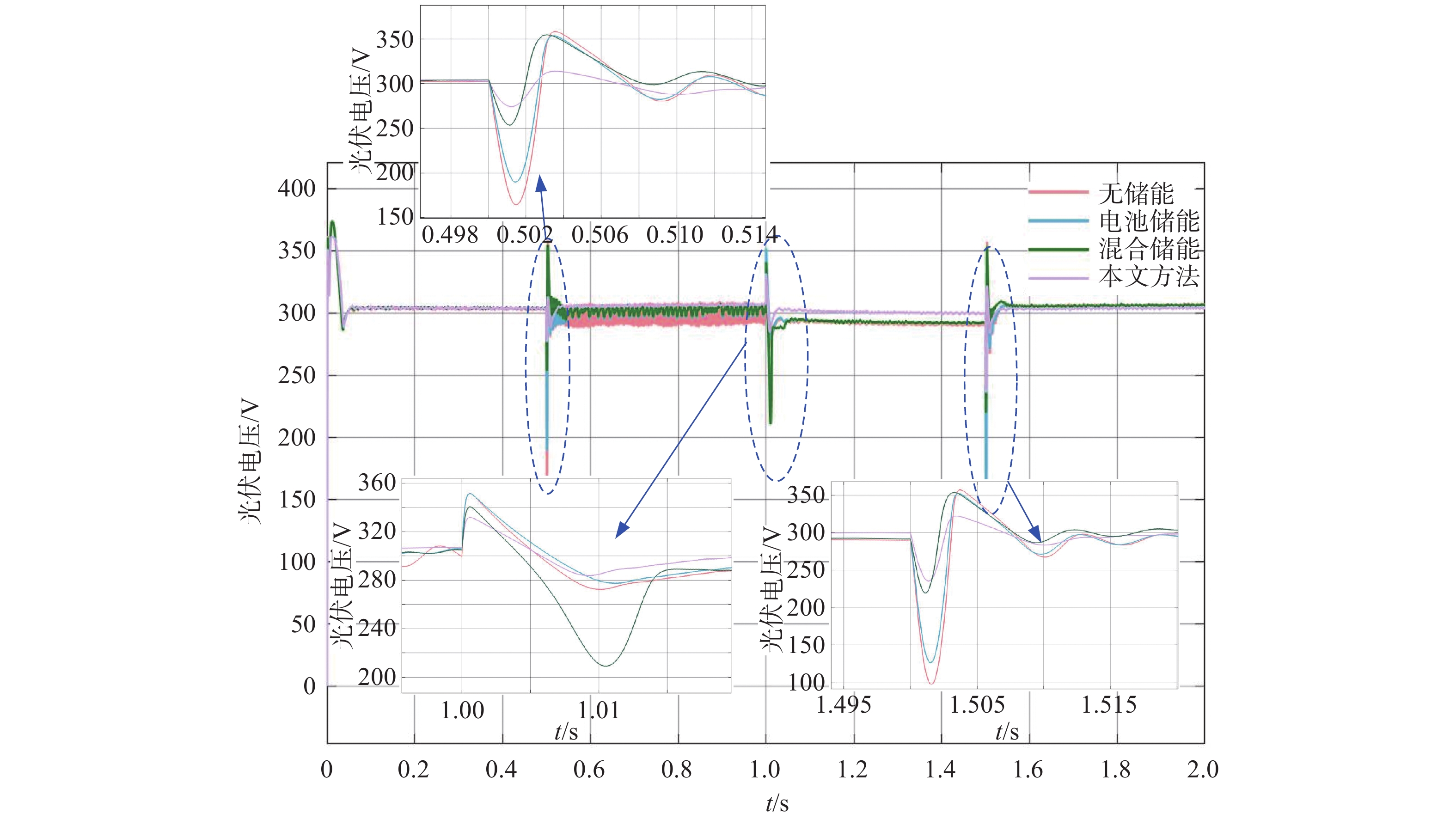
图8为光伏输出电压波形,通过图8,我们可以观察到,当光伏系统受信号干扰时,使用文章提出的方法得到的光伏输出电压波形相比于无储能、电池储能和混合储能的光伏输出电压波形表现的更为稳定,波动幅度更小且在允许的控制范围内。其中,带混合储能的光伏输出电压波动比带电池储能的光伏输出电压波动小,无储能条件下的光伏输出电压表现出最明显的波动。

Figure 8. Photovoltaic output voltage waveform
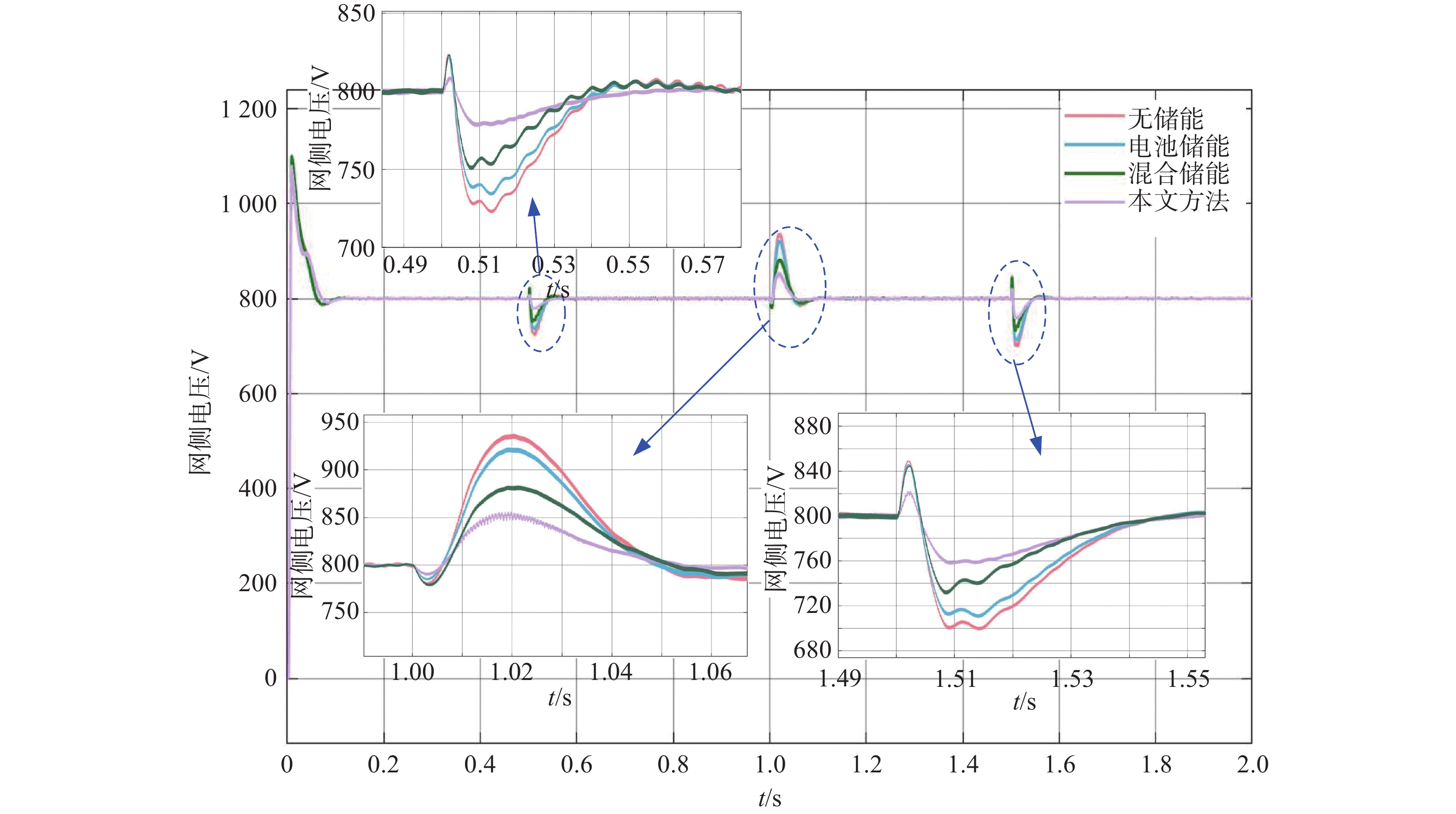
图9为网侧输出电压波形,可以看出,使用文章方法得到的网侧电压波形的波动幅度是最小且最稳定的,最为稳定且在允许的控制范围内。与带电池储能相比,带混合储能的网侧输出电压波形的波动范围更小,在无储能条件下,其网侧输出电压波形的波动是最大的。

Figure 9. Network side output voltage waveform
-
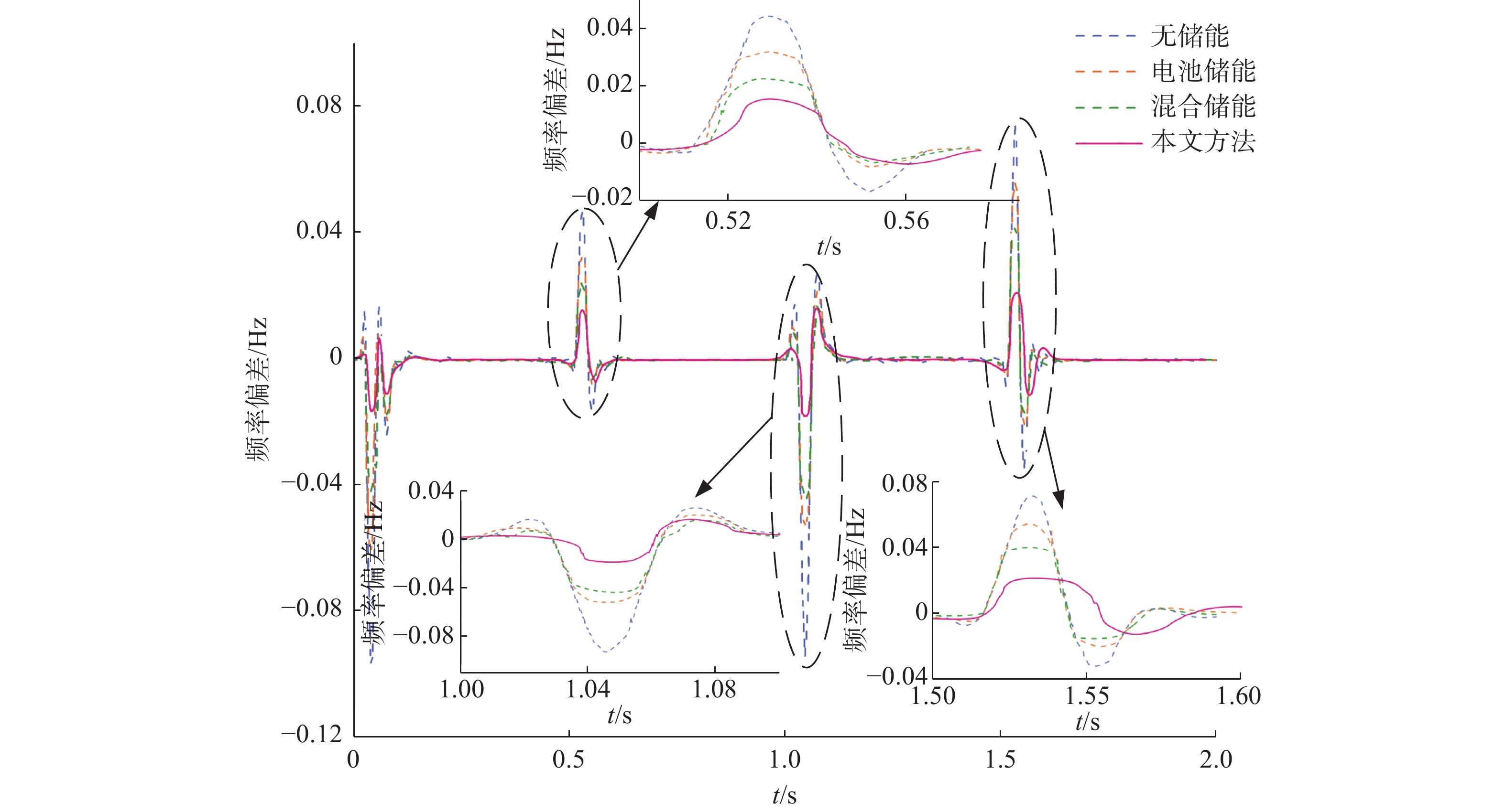
为验证文章采用的方法对光伏并网系统调频优化效果,在无储能、带电池储能、带混合储能以及文章所提方法这4种不同控制策略下,进行了光伏并网的仿真分析。在这里,依次将无储能、电池储能、混合储能、文章所提方法设置为策略1、策略2、策略3、策略4,并对他们的频率偏差进行了仿真比较分析,如图10所示。显然,在不同策略下,光伏并网系统频率在0.5 s、1 s、1.5 s附近产生较明显的频率偏差。在波动的时间范围内,依次将其定义为波动区间1、波动区间2和波动区间3。在不同策略中,频率偏差的波动情况不同。如表3所示,策略1的频率偏差和偏差差值是最大的,即该系统频率波动范围最大,策略2的频率波动情况较策略1有所改善,策略3的频率波动情况又比策略2有进一步的改善。

Figure 10. Changes in system frequency deviation
控制策略 扰动 最大频率偏差/Hz 最大频率偏差差值 策略1 扰动1 0.046 0.063 扰动2 −0.094 0.121 扰动3 0.074 0.108 策略2 扰动1 0.032 0.040 扰动2 −0.053 0.074 扰动3 0.055 0.076 策略3 扰动1 0.024 0.031 扰动2 −0.044 0.061 扰动3 0.041 0.058 策略4 扰动1 0.016 0.024 扰动2 −0.019 0.037 扰动3 0.020 0.035 Table 3. System frequency modulation evaluation index under different control strategies
在3个不同的波动范围中,文章所采用的基于MPC的光-储并网系统的频率波动幅度是最小的。在波动区间1内,与策略1、策略2和策略3相比较,文章所提出的策略在最大频率偏差上分别降低了65.22%、50%和33.33%;在波动区间2内,与策略1、策略2和策略3相比较,文章所提出的策略在最大频率偏差上分别降低了78.14%、64.15%和56.82%;在波动区间3内,与策略1、策略2和策略3相比较,文章所提出的策略在最大频率偏差上分别降低了73%、63.63%和51.21%。综上可得,文章所提出的策略进一步提升了光伏并网系统的频率稳定性。
-
针对大规模高渗透率的新能源并网导致电网频率波动的问题,文章研究了基于MPC的光-储协同调频优化策略,并在MATLAB/Simulink平台上进行了仿真实验,实验结果证明,与其他策略相比,文章策略在光伏并网调频方面具有更优性。基于此,可以得出如下结论:
1)文章采用的混合储能出力较为平滑。在光伏出力波动的时间段内,电池储能能够快速进行低频补偿。同理,超级电容能够在0.5 s、1 s、1.5 s时刻快速进行的高频补偿,从而使系统功率能够快速恢复到平稳状态,提高系统频率稳定性。
2)文章所提出的基于MPC预测控制策略考虑了光储电站有功出力和总发电量等约束条件,以光伏功率偏差、电网电压偏差和系统频率偏差最小为目标,通过滚动优化,进一步优化了光伏并网系统频率的稳定性。
Optimization Strategy for Collaborative Frequency Modulation of PVs-ESs Based on MPC
doi: 10.16516/j.ceec.2024.2.12
- Received Date: 2023-10-17
- Rev Recd Date: 2023-11-14
- Available Online: 2024-03-25
- Publish Date: 2024-03-26
-
Key words:
- collaborative frequency modulation /
- PVs-ESs /
- MPC /
- hybrid energy storage /
- electrical power systems
Abstract:
| Citation: | YAN Xiaoshan, TANG Huiling, WU Jiekang, et al. Optimization strategy for collaborative frequency modulation of pvs-ess based on MPC [J]. Southern energy construction, 2024, 11(2): 125-138 doi: 10.16516/j.ceec.2024.2.12

|

 DownLoad: