• Peer Review
  • Non-profit
  • Global Open Access
  • Green Channel for Rising Stars
Volume 1 Issue 1
Jul.  2020
Turn off MathJax
Article Contents

Jingjing HUANG. Analysis and Discussion on a Maloperation of Transformer Backup Protection Caused by Inrush Current[J]. SOUTHERN ENERGY CONSTRUCTION, 2014, 1(1): 106-110. doi: 10.16516/j.gedi.issn2095-8676.2014.01.020
Citation: Jingjing HUANG. Analysis and Discussion on a Maloperation of Transformer Backup Protection Caused by Inrush Current[J]. SOUTHERN ENERGY CONSTRUCTION, 2014, 1(1): 106-110. doi: 10.16516/j.gedi.issn2095-8676.2014.01.020

Analysis and Discussion on a Maloperation of Transformer Backup Protection Caused by Inrush Current

doi: 10.16516/j.gedi.issn2095-8676.2014.01.020
  • Received Date: 2014-10-01
  • Publish Date: 2014-12-25
  • In order to study the effect of inrush current to the backup protection of transformer, a maloperation of transformer backup protection is presented in this paper, which is caused by inrush current emerged during the no-load switching of the new transformer in a 220 kV substation. The equivalent circuit model of the no-load switching transformer is established which derives the differential equation of the transformer magnetic flux. The mechanism of inrush current and the factors related to amplitude and attenuation are analyzed. Then some conclusions are presented. The theoretical results are verified by the real fault recorder data. According to the slow attenuation of inrush current, some measures are proposed to avoid the maloperation of backup protection, which have been verified in practice.
  • [1] 黄家栋,罗伟强. 采用改进数学形态学识别变压器励磁涌流的新方法 [J]. 中国电机工程学报,2009,29(7):98-105.

    HUANG Jiadong, LUO Weiqiang. New Algorithm to Identify Inrush Current Based on Improved Mathematical Morphology [J]. Proceedings of the CSEE, 2009, 29(7):98-105.
    [2] 马静,王增平,吴颉. 利用基波幅值变化特征快速识别励磁涌流和故障电流 [J]. 电工技术学报,2009, 24(6):166-171.

    MA Jing, WANG Zengping, WU Jie. A Novel Method to Rapidly Identify Inrush Current and Interal Fault Current Based on Variation Characteristic of Fundamental Current Amplitude[J]. Transactions of China Electrotechnical Society, 2009, 24(6):166-171.
    [3] 郑涛,张婕,高旭. 一起特高压变压器的差动保护误动分析及防范措施 [J]. 电力系统自动化,2011, 35(18):92-97.

    ZHENG Tao, ZHANG Jie, GAO Xu. Analysis on a Mal-operation of Differential Protection for Ultra-high Voltage Transformer and Its Countermeasure [J]. Automation of Electric Power Systems. 2011, 35(18):92-97.
    [4] 承文新,刘志超. 变压器差动保护涌流制动原理分析 [J]. 电力系统自动化,2006, 30(11):90-92.

    CHENG Wenxin, LIU Zhichao. Analysis of Inrush Restraint Theory for Transformer Differential Protection[J]. Automation of Electric Power Systems, 2006, 30(11):90-92.
    [5] 金恩淑,刘丽丽,姜龙澈,等. 变压器电流差动保护改进方法[J]. 电力系统自动化,2008, 32(9):47-51.

    JIN Enshu, LIU Lili, JIANG Longzhe, et al. An Improved Method of Transformer Differential Protection [J]. Automation of Electric Power Systems. 2008, 32(9):47-51.
    [6] 赵萍. 一起主变差动保护误动实例分析及对策探讨 [J]. 电力系统自动化,2009, 33(20):104-107.

    ZHAO Ping. Analysis and Countermeasures on a Case of Mal-Operation of Transformer Differential Protection[J]. Automation of Electric Power Systems, 2009, 33(20):104-107.
    [7] 郑涛,曹志辉. 基于模糊逻辑的变压器励磁涌流二次谐波闭锁方案 [J]. 电力系统自动化,2009, 33(2):61-65.

    ZHENG Tao, CAO Zhihui. Scheme for Second Harmonic Block of Magnetizing Inrush Current in Transformers Based on Fuzzy Logic [J]. Automation of Electric Power Systems, 2009, 33(2):61-65.
    [8] 何仰赞,温增银. 电力系统分析[M]. 3版. 武汉:华中科技大学出版社,2002.

    HE Yangzan, WEN Zengyin. Power System Analysis[M].3rd ed.Wuhan: Huazhong University of Science and Technology Press, 2002.
  • 通讯作者: 陈斌, bchen63@163.com
    • 1. 

      沈阳化工大学材料科学与工程学院 沈阳 110142

    1. 本站搜索
    2. 百度学术搜索
    3. 万方数据库搜索
    4. CNKI搜索

Figures(4)  / Tables(2)

Article Metrics

Article views(247) PDF downloads(33) Cited by()

Related

Analysis and Discussion on a Maloperation of Transformer Backup Protection Caused by Inrush Current

doi: 10.16516/j.gedi.issn2095-8676.2014.01.020

Abstract: In order to study the effect of inrush current to the backup protection of transformer, a maloperation of transformer backup protection is presented in this paper, which is caused by inrush current emerged during the no-load switching of the new transformer in a 220 kV substation. The equivalent circuit model of the no-load switching transformer is established which derives the differential equation of the transformer magnetic flux. The mechanism of inrush current and the factors related to amplitude and attenuation are analyzed. Then some conclusions are presented. The theoretical results are verified by the real fault recorder data. According to the slow attenuation of inrush current, some measures are proposed to avoid the maloperation of backup protection, which have been verified in practice.

Jingjing HUANG. Analysis and Discussion on a Maloperation of Transformer Backup Protection Caused by Inrush Current[J]. SOUTHERN ENERGY CONSTRUCTION, 2014, 1(1): 106-110. doi: 10.16516/j.gedi.issn2095-8676.2014.01.020
Citation: Jingjing HUANG. Analysis and Discussion on a Maloperation of Transformer Backup Protection Caused by Inrush Current[J]. SOUTHERN ENERGY CONSTRUCTION, 2014, 1(1): 106-110. doi: 10.16516/j.gedi.issn2095-8676.2014.01.020
  • 变压器作为电力系统的主要设备,其正常运行对电力系统安全稳定至关重要。励磁涌流是影响变压器空载合闸的重要因素。目前的研究主要是关注鉴别励磁涌流的特征以及防止励磁涌流引起差动保护误动[1-7]。这些研究对防止差动保护误动起到很好的效果,并已在电力系统得到广泛应用。而在电力系统实际运行中,在某些系统工况下,产生的励磁涌流幅值大,并且衰减较为缓慢,会对变压器和系统其它设备的后备保护产生影响。由励磁涌流引起变压器后备保护误动作的事故时有发生。而目前对励磁涌流衰减问题的研究与分析的文献还比较少。本文针对近期发生的一起变压器空载充电时后备保护误动案例,进行了理论分析推导,并结合故障录波数据和保护的实际动作情况,分析出误动原因,并提出了一些防范措施。

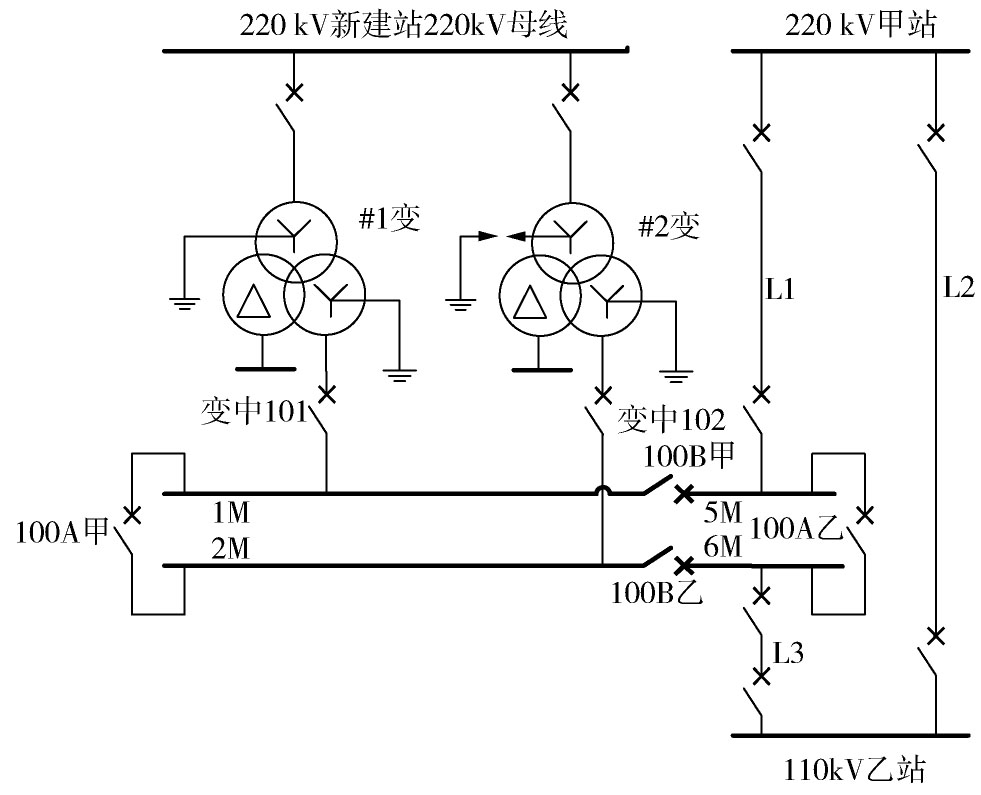
  • 变压器空载充电时的运行方式如图1所示。220 kV某新建变电站,按计划于2013年12月28日晚间,对该站# 1、# 2变压器进行充电试验。因220 kV线路尚未完成建设,不具备从220 kV侧充电的条件,故采用从变压器110 kV侧向变压器充电的方式。

    Figure 1.  The System Operation Mode of a 220 kV Substation

    图1所示,220 kV甲站经110 kV L1线向该新建站的110 kV 5M母线供电。110 kV乙站经110 kV L3线向110 kV 6M供电。并且220 kV甲站与110 kV乙站通过110 kV L2线路相连。L1、L2、L3的线路长度分别为5.410 km、5.034 km、0.778 km。充电时,线路断路器、母联断路器均闭合。

    对# 1变进行了4次充电、# 2变进行了3次充电,涌流情况及保护动作情况,分别如表1表2所示。

    # 1主变充电时刻 涌流 保护动作情况
    涌流峰值/A 半波衰减时间/s
    19:16:50 3 300 0.32
    21:38:11 1 400 0.38
    22:18:19 6 900 0.24 主一保护过流I段t 2时限动作 动作值0.625 A(937.5 A) 动作时间514 ms 方向元件退出 复压元件退出
    主二保护过流I段t 2时限动作 动作值0.607 A(910.5 A) 动作时间505 ms 方向元件退出 复压元件退出
    22:31:36 5 900 0.23 100A甲零序过流I段动作 动作值0.81 A(972 A) 动作时间200 ms    
    100B乙零序过流I段动作 动作值0.81 A(972 A) 动作时间200 ms    

    Table 1.  The Test Results of # 1 Transformer

    # 2主变充电时刻 涌流 保护动作情况
    涌流峰值/A 半波衰减时间/s
    20:18:55 4 300 0.34 100A甲零序过流II段动作 动作值0.39 A(468 A) 动作时间600 ms
    100B乙零序过流II段动作 动作值0.4 A(480 A) 动作时间600 ms
    22:03:39 4 300 0.32 100A甲零序过流II段动作 动作值0.36 A(432 A) 动作时间1 000 ms
    100B乙零序过流II段动作 动作值0.36 A(432 A) 动作时间1 000 ms
    22:27:14 6 700 0.24 主一保护过流I段t 2时限动作 动作值0.625 A(937.5 A) 动作时间505 ms
    主二保护过流I段t 2时限动作 动作值0.611 A(916.5 A) 动作时间507 ms

    Table 2.  The test Results of # 2 Transformer

    # 1主变第1、2次充电时正常。第3、4次充电,后备保护均动作跳闸。从表1可知,励磁涌流幅值很大,远大于保护动作值,半波衰减时间长,且在主变充电时主变后备保护方向和复压闭锁元件未投入,母联/分段保护不经复压闭锁,经延时保护正确动作。

    # 2主变3次充电励磁涌流值都很大,且半波衰减时间长,3次充电后备保护均动作。

  • 为简单起见,下面以主变压器的单相为例,简要分析空充时励磁涌流产生的机理。
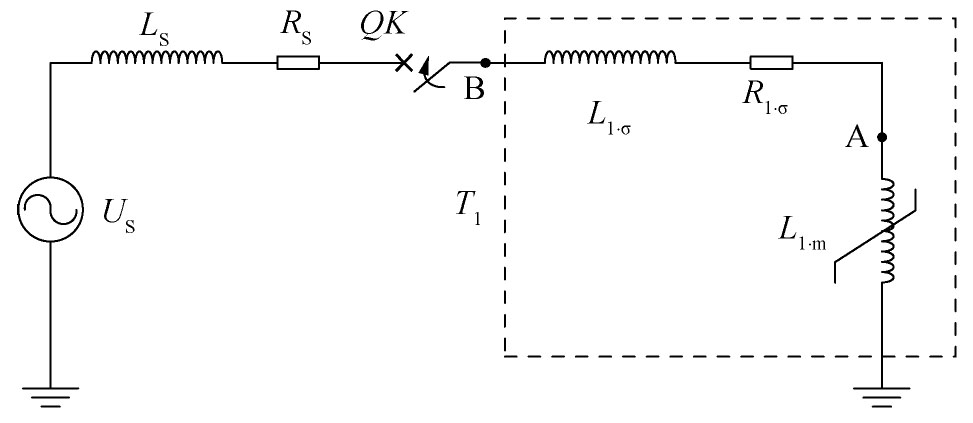
    图2所示为主变单相110 kV侧空充的电路模型,US为等效的110 kV侧无穷大电源,LSRS为110 kV系统等效电感和电阻,QF为主变110 kV侧断路器,L1.σ为变压器一次侧漏感,R1.σ为一次侧串联电阻,等于变压器110 kV侧线圈的直流电阻,L1.m为变压器励磁电感。

    Figure 2.  The Equivalent Model of Single Phase Transformer Charging

    设变压器T1t=0时刻合闸,电压合闸角为α,则原边回路电压方程为:

    ((1))

    其中RRSR1.σ为回路电阻。Φ为原边回路总磁通,满足

    ((2))

    ΦT为变压器铁芯磁通,可等效为励磁电感L1.m产生的磁通。即ΦTL1.mi。实际上,L1.m是一个非线性电感,其值按照变压器励磁曲线计算得到,为了定性分析励磁涌流暂态过程,暂且使用近似直线特性,即把L1.m当成一个线性电感简化处理。将代入微分方程(1),得到以磁链Φ为变量的微分方程:

    ((3))

    解此微分方程得:

    ((4))
    ((5))

    式中,Φm为稳态磁通幅值且满足Φr铁心剩磁通,τ为变压器一次侧空载合闸回路时间常数,φ=arctan(ωL/R)。

    由式(4)可知,变压器的暂态磁链Φ由稳态交流分量和暂态直流分量两部分组成。稳态交流分量的幅值是固定的,若暂态直流分量足够大,则会使变压器铁芯产生较大的偏磁而进入饱和状态,使L1.m急剧减小,产生励磁涌流。

    暂态直流分量的大小与空载合闸时电压初相角、剩磁的大小和方向、变压器空载合闸回路的阻抗角度φ有关。且励磁涌流的衰减的速度取决于时间常数τ,若回路的电感L越大,电阻R越小,则衰减时间越长。

    该新建站在正常运行方式下,由L2与L1线、L3线并列运行供电。忽略系统阻抗和变压器阻抗中的电阻分量[8],令系统电抗和变压器电抗为jXs

    令110 kV线路每公里长度的电阻为R0,电抗为X0。则L2与L1线、L3线并联时的等效阻抗为2.8(R0jX0)。

    则在正常运行方式下,变压器合闸总阻抗为:

    ((6))

    励磁涌流的衰减时间常数为:

    ((7))

    在2014年1月3日进行该站第2次启动时,将L3线新建站侧开关断开为热备用,新建站仅经L1线供电,此时,线路的阻抗值为5.41(R0jX0),变压器合闸合闸总阻抗为:

    励磁涌流的衰减时间常数为:

    ((8))

    比较式(7)和式(8),可知τ′<τ

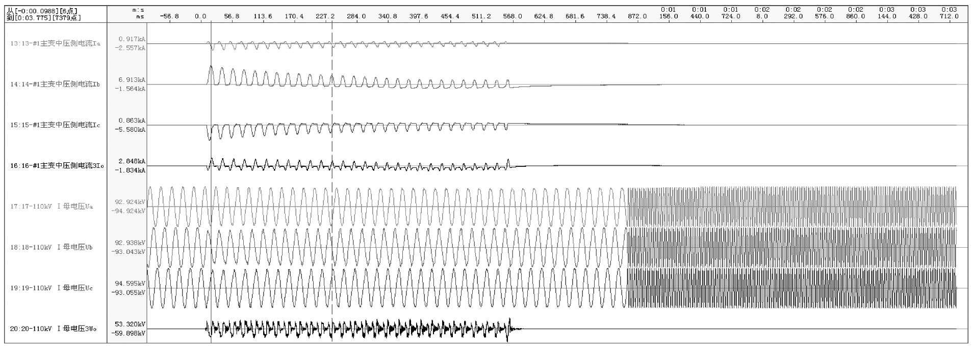
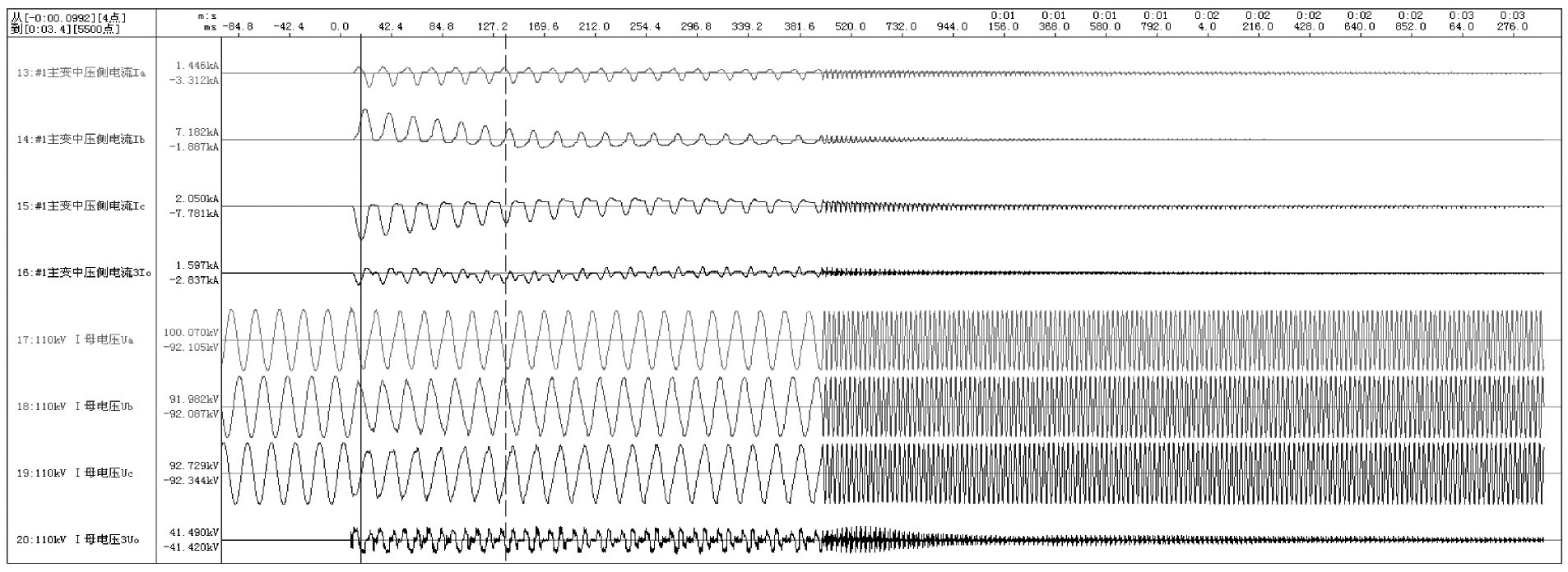
    由此可见,在第2次启动时,时间常数减小,励磁涌流衰减速度明显快于第1次。第1次启动时由L2与L1线、L3线并列运行供电,实际录波波形如图3所示,# 1主变励磁涌流半波衰减时间t1为0.2~0.3 s,第2次启动时,仅经L1线供电,实际录波波形如图4所示,# 1主变励磁涌流的半波衰减时间t2为0.1~0.2 s,t2<t1验证了前面的结论。

    Figure 3.  The Inrush Current of # 1 Transformer Charging(Dec.28,2013)

    Figure 4.  The Inrush Current of # 1 Transformer Charging(Jan.3,2014)

    表1可知,由于励磁涌流幅值很大,远大于保护动作值,当半波衰减时间大于后备保护整定时间且满足复压闭锁条件时,经延时后备保护动作。

  • 针对上述主变启动时,励磁涌流大且励磁涌流衰减缓慢导致后备保护误动作,提出以下防范措施:

    1)在保证保护灵敏度的前提下,在后备保护中增加励磁涌流判别,防止励磁涌流导致的保护误动作。

    2)由于励磁涌流对系统电压影响较小,而发生短路故障时,电压会有明显的下降,可引入电压闭锁元件,有效区分励磁涌流和短路故障。

    3)在变电站主变送电时,合理调整运行方式,应尽量避免来自同一电源侧的两条线路并列运行,以防止励磁涌流衰减过慢。

  • 本文从一起典型的变电站主变充电时后备保护误动作事件出发,根据励磁涌流产生及衰减的原理,透彻分析导致此次涌流大及衰减时间长的原因,并提出了三种切实可行的防范措施。

Reference (8)

Catalog

    /

    DownLoad:  Full-Size Img  PowerPoint
    Return
    Return