• Peer Review
  • Non-profit
  • Global Open Access
  • Green Channel for Rising Stars
Volume 4 Issue 2
Jul.  2020
Turn off MathJax
Article Contents

Xin CHANG, Li XU, Zhenhua WANG, Donghong ZHANG. Mechanical Analysis and Design Suggestions of Steel Tubular Tower with Eccentric Joint[J]. SOUTHERN ENERGY CONSTRUCTION, 2017, 4(2): 90-94. doi: 10.16516/j.gedi.issn2095-8676.2017.02.016
Citation: Xin CHANG, Li XU, Zhenhua WANG, Donghong ZHANG. Mechanical Analysis and Design Suggestions of Steel Tubular Tower with Eccentric Joint[J]. SOUTHERN ENERGY CONSTRUCTION, 2017, 4(2): 90-94. doi: 10.16516/j.gedi.issn2095-8676.2017.02.016

Mechanical Analysis and Design Suggestions of Steel Tubular Tower with Eccentric Joint

doi: 10.16516/j.gedi.issn2095-8676.2017.02.016
  • Received Date: 2017-01-04
  • Publish Date: 2020-07-18
  • The K type connecting plate is used for connecting main member and brace member of steel tubular tower. The centroid of members shall intersect at one point as much as possible. The weight of joint and wind area of tower were increased for the large connecting plate due to small included angle between main member and brace member. The size of the connecting plate will be reduced when using the eccentric joint. The entire finite element model with eccentric joint was employed to study mechanical behavior of main member and brace member. The results shown that mechanical behavior of main member and brace member were less affected by eccentric joint. The recommended design method of steel tubular tower with eccentric joint was proposed and the results can be used as a reference for engineering application and theoretical study.
  • [1] 吴静,邓洪洲,傅俊涛. 输电塔圆钢管相贯节点强度分析 [J]. 特种结构,2006,23(3): 63-65.

    WU J, DENG H Z, FU J T. Strength analysis of steel tubular intersection k-joint for transmission line [J]. Special Structures,2006,23(3): 63-65.
    [2] 高翔,邹相国,王勇. 输电钢管塔相贯节点非线性分析 [J]. 机械设计,2009,26(9): 70-72.

    GAO X, ZOU X G, WANG Y. Nonlinear analysis on intersection node of the steel pipe tower of power transmission [J]. Journal of Machine Design,2009,26(9): 70-72.
    [3] 邓洪洲,黄誉,金晓华. 钢管塔新型内外法兰节点试验研究与有限元分析 [J]. 建筑结构学报,2009,30(5): 140-148.

    DENG H Z, HUANG Y, JIN X H. Experimental research and finite element analysis on a new-type flange joint used in steel tube towers [J]. Journal of Building Structures,2009,30(5): 140-148.
    [4] 鲍侃袁,沈国辉,孙炳楠,等. 高耸钢管塔K型结点极限承载力的试验研究与理论分析 [J]. 工程力学,2008,25(12): 114-122.

    BAO K Y, SHEN G H, SUN B N,et al. Experimental study and theoretical analysis of ultimate strength of steel tubular k-joints of tall tower [J]. Engineering Mechanics,2008,25(12): 114-122.
    [5] 潘峰,应建国. 1 000 kV钢管塔十字插板连接K型节点的非线性分析 [J]. 电力建设,2010,31(12): 38-42.

    PAN F, YING J G. Nonlinear analysis of steel tube tower k-joints with cross flashboard for 1 000 kV UHV lines [J]. Electric Power Construction,2010,31(12): 38-42.
    [6] 电力规划设计标准化技术委员会. 架空送电线路杆塔结构设计技术规定:DL/T 5154-2002 [S]. 北京:中国电力出版社,2002.

    Technical Committee for Standardization of Electric Power Planning and Design.Technical regulation of design for tower and pole structures of overhead transmission line: DL/T 5154-2002 [S]. Beijing:China Electric Power Press,2002.
    [7] 电力规划设计标准化技术委员会. 架空送电线路钢管塔设计技术规定:DL/T 5254-2010 [S]. 北京:中国电力出版社,2010.

    Technical Committee for Standardization of Electric Power Planning and Design. Technical regulation of design for steel tubular tower structures of overhead transmission line: DL/T 5254-2010 [S]. Beijing:China Electric Power Press,2010.
    [8] 中华人民共和国建设部. 钢结构设计规范:GB 50017-2003 [S]. 北京:中国计划出版社,2003.

    Ministry of Construction of the People's Republc of China.. Code for design of concrete structure: GB 50017-2003 [S]. Beijing:China Planning Press,2003.
    [9] 黄誉. 输电线路钢管塔节点强度理论与试验研究 [D]. 上海:同济大学,2010.

    HUANG Y. Studies on steel tubular joints of transmission tower [D]. Shanghai:Tongji University,2010.
    [10] ANSYS, Inc. ANSYS release 11.0 documentation [M]. Canonsburg, PA: ANSYS, Inc., 2007.
  • 通讯作者: 陈斌, bchen63@163.com
    • 1. 

      沈阳化工大学材料科学与工程学院 沈阳 110142

    1. 本站搜索
    2. 百度学术搜索
    3. 万方数据库搜索
    4. CNKI搜索

Figures(5)  / Tables(6)

Article Metrics

Article views(177) PDF downloads(8) Cited by()

Related

Mechanical Analysis and Design Suggestions of Steel Tubular Tower with Eccentric Joint

doi: 10.16516/j.gedi.issn2095-8676.2017.02.016

Abstract: The K type connecting plate is used for connecting main member and brace member of steel tubular tower. The centroid of members shall intersect at one point as much as possible. The weight of joint and wind area of tower were increased for the large connecting plate due to small included angle between main member and brace member. The size of the connecting plate will be reduced when using the eccentric joint. The entire finite element model with eccentric joint was employed to study mechanical behavior of main member and brace member. The results shown that mechanical behavior of main member and brace member were less affected by eccentric joint. The recommended design method of steel tubular tower with eccentric joint was proposed and the results can be used as a reference for engineering application and theoretical study.

Xin CHANG, Li XU, Zhenhua WANG, Donghong ZHANG. Mechanical Analysis and Design Suggestions of Steel Tubular Tower with Eccentric Joint[J]. SOUTHERN ENERGY CONSTRUCTION, 2017, 4(2): 90-94. doi: 10.16516/j.gedi.issn2095-8676.2017.02.016
Citation: Xin CHANG, Li XU, Zhenhua WANG, Donghong ZHANG. Mechanical Analysis and Design Suggestions of Steel Tubular Tower with Eccentric Joint[J]. SOUTHERN ENERGY CONSTRUCTION, 2017, 4(2): 90-94. doi: 10.16516/j.gedi.issn2095-8676.2017.02.016
  • 500 kV东海岛输变电工程位于湛江地区,起点500 kV港城变电站,落点500 kV东海岛变电站,线路经过大约8 km的滨海滩涂地带,设计风速高达37 m/s,风荷载大,普通角钢无法满足风荷载的承载力要求。钢管构件具有体型系数小、截面刚度大、受力性能好的特点,该工程全线采用钢管塔设计。

    钢管塔的杆件连接形式主要包括:相贯[1,2]、法兰[3]、连接板[4]等,其中连接板形式应用最为广泛。规范[6,7]要求钢管形心线尽可能交汇于一点,当钢管塔斜材与主材之间夹角较小时,为了避免杆件之间相碰,其连接板的尺寸相对较大,造成节点重量增加和塔身挡风面积增大。规范规定[7,8]:当斜材端部与主材管壁之间的距离c与节点板厚度t之比大于10 时,需要计算节点板稳定性;当节点板的自由边长度lf与厚度t之比大于60 时,应沿自由边设加劲肋予以加强,这无疑增加了节点的设计难度和构造复杂性。文献[9]对无偏心和负偏心钢管塔节点进行了节点试验和有限元分析,其研究表明无偏心和负偏心两类节点破坏模式相同,其受力性能基本相同,负偏心节点安全可靠,可用于实际工程。

    当斜材偏心后,结构的传力路径会发生变化,目前输电线路行业传统通用的铁塔设计软件暂时还无法考虑偏心节点,因此有必要建立偏心节点的有限元整体模型进行受力分析,研究偏心节点连接对主材以及斜材的受力影响,并给出偏心节点钢管塔的设计建议,为其工程应用和理论研究提供参考。

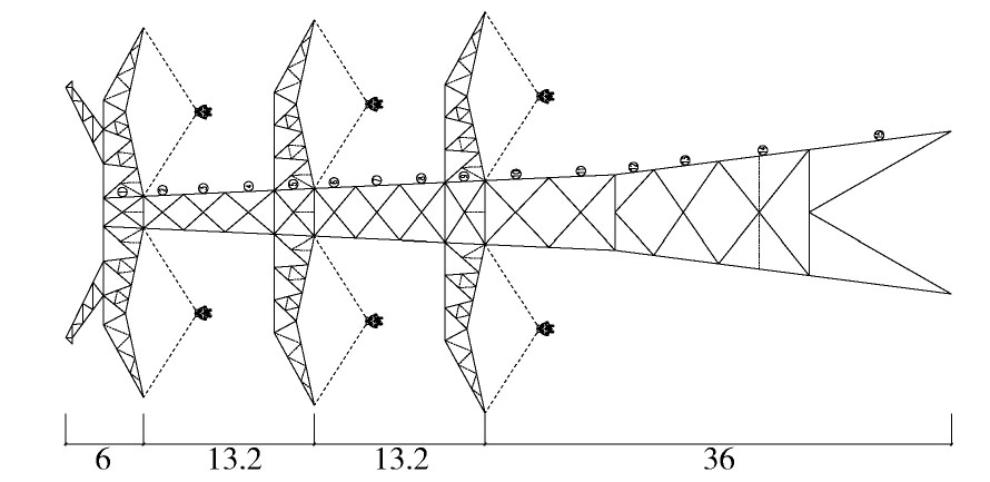
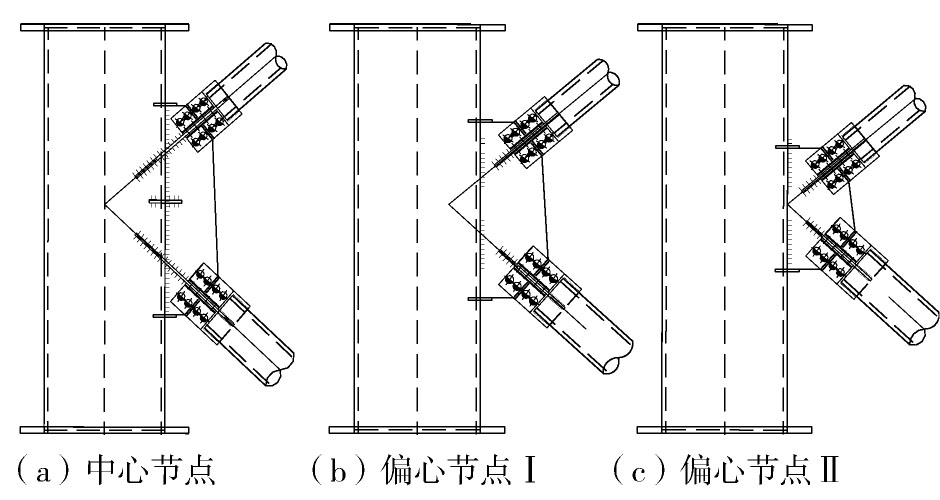
  • 铁塔斜材与主材连接传统方式如图1(a)所示,斜材与主材的重心线相交,此种中心节点的节点板尺寸相对较大,增加了塔重和结构挡风面积;为了减小节点板尺寸,将斜材中心线相交于主材1/4主管径(图1(b))或1/2主管径(图1(c)),此种偏心节点可以有效减小节点板的尺寸,进而可以减小结构自重和结构挡风面积,具有较好的经济意义。为研究偏心节点后铁塔主材与斜材的受力性能,选取一V串钢管直线塔作为研究对象,铁塔全高68.4 m,塔头至塔脚共15段,如图2所示。用ANSYS[10]建立了偏心节点的铁塔有限元模型,主材采用beam4梁单元,斜材采用link8杆单元,斜材内力通过刚性梁单元传递至主材。

    Figure 1.  Connecting type of brace member and main member

    Figure 2.  Single line drawing of the tower

  • 塔身主材的主要控制工况为大风工况,塔身斜材的主要控制工况为断线工况,因此选取90°大风、45°大风和断线工况分析。其本文侧重研究偏心对主材和斜材的影响,对主材和斜材进行稳定计算,塔身主材采用梁单元,按压弯构件计算稳定承载力;塔身斜材采用杆单元,按轴心受压构件计算稳定承载力。

    主材编号M1-M11为变坡以上杆件,M12-M15为变坡以下杆件。表1,表2,表3分别给出了三种工况下中心节点、偏心节点Ⅰ和偏心节点Ⅱ三种模型的塔身主材应力,由表可以看出:偏心节点对变坡以上主材应力影响相对较大,对变坡以下主材应力影响非常小,主要是由于变坡以上主材应力较小,因此引起的杆件应力比变化较大,反之,变坡以下主材应力较大,因此引起的杆件应力比变化较小;偏心越大,其对变坡以上主材应力影响越大,但对变坡以下主材杆件几乎没影响;个别杆件的偏心节点模型的应力与中心节点模型的应力比值较大,主要是由于其中心节点模型的原始应力较小,但其应力增加绝对值并不大。

    主材编号 中心节点 偏心节点Ⅰ 偏心节点Ⅱ
    最大应力σm1/MPa 最大应力σm2/MPa 比值σm2/σm1 最大应力σm3/MPa 比值σm3/σm1
    M1 54 77 1.44 101 1.88
    M2 104 122 1.17 143 1.37
    M3 161 204 1.27 249 1.55
    M4 147 153 1.04 178 1.21
    M5 179 173 0.96 177 0.99
    M6 245 232 0.95 249 1.02
    M7 189 217 1.15 245 1.29
    M8 250 235 0.94 223 0.89
    M9 205 214 1.05 223 1.09
    M10 240 228 0.95 231 0.96
    M11 241 253 1.05 266 1.10
    M12 281 277 0.99 274 0.97
    M13 258 257 1.00 256 0.99
    M14 259 258 1.00 257 0.99
    M15 280 280 1.00 279 1.00

    Table 1.  Stress of main member under 90° wind case

    主材编号 中心节点 偏心节点Ⅰ 偏心节点Ⅱ
    最大应力σm1/MPa 最大应力σm2/MPa 比值σm2/σm1 最大应力σm3/MPa 比值σm3/σm1
    M1 33 52 1.58 71 2.19
    M2 120 140 1.17 164 1.37
    M3 237 261 1.10 294 1.24
    M4 168 172 1.02 192 1.14
    M5 214 225 1.05 235 1.09
    M6 294 281 0.96 282 0.96
    M7 229 250 1.09 278 1.22
    M8 270 264 0.98 257 0.95
    M9 236 246 1.04 255 1.08
    M10 272 261 0.96 249 0.91
    M11 262 274 1.04 286 1.09
    M12 305 301 0.99 298 0.98
    M13 275 274 1.00 274 1.00
    M14 267 267 1.00 268 1.00
    M15 296 296 1.00 295 1.00

    Table 2.  Stress of main member under 45° wind case

    主材编号 中心节点 偏心节点Ⅰ 偏心节点Ⅱ
    最大应力σm1/MPa 最大应力σm2/MPa 比值σm2/σm1 最大应力σm3/MPa 比值σm3/σm1
    M1 20 50 2.47 75 3.73
    M2 118 150 1.27 186 1.58
    M3 125 148 1.18 215 1.73
    M4 73 91 1.26 123 1.70
    M5 111 120 1.08 127 1.15
    M6 130 137 1.06 146 1.12
    M7 83 83 1.00 89 1.07
    M8 84 84 1.00 84 1.00
    M9 81 80 0.99 82 1.02
    M10 79 79 1.01 83 1.06
    M11 68 70 1.02 71 1.04
    M12 73 73 1.00 73 1.00
    M13 56 56 0.99 57 1.01
    M14 58 57 0.99 59 1.02
    M15 64 65 1.02 66 1.03

    Table 3.  Stress of main member under broken wire case

    斜材编号B1-B11为变坡以上杆件,B12-B15为变坡以下杆件。表4,表5,表6分别给出了三种工况下中心节点、偏心节点Ⅰ和偏心节点Ⅱ三种模型的塔身斜材的应力,由表可以看出:不同位置的塔身斜材,其偏心节点模型的应力相比中心节点模型的应力有增大也有减小,但总体上偏心节点引起的塔身斜材的应力变化很小,可以忽略其影响。

    斜材编号 中心节点 偏心节点Ⅰ 偏心节点Ⅱ
    最大应力σb1/MPa 最大应力σb2/MPa 比值σb2/σb1 最大应力σb3/MPa 比值σb3/σb1
    B1 173 171 0.99 171 0.99
    B2 249 250 1.01 251 1.01
    B3 264 257 0.97 251 0.95
    B4 229 226 0.99 221 0.97
    B5 36 31 0.86 27 0.76
    B6 262 261 1.00 260 0.99
    B7 221 210 0.95 200 0.90
    B8 203 199 0.98 195 0.96
    B9 165 155 0.94 145 0.88
    B10 290 284 0.98 276 0.95
    B11 262 260 0.99 258 0.98
    B12 67 61 0.91 55 0.82
    B13 42 41 0.97 40 0.95
    B14 63 63 1.00 63 1.00
    B15 101 102 1.01 103 1.02

    Table 4.  Stress of brace member under 90° wind case

    斜材编号 中心节点 偏心节点Ⅰ 偏心节点Ⅱ
    最大应力σb1/MPa 最大应力σb2/MPa 比值σb2/σb1 最大应力σb3/MPa 比值σb3/σb1
    B1 196 193 0.98 187 0.96
    B2 201 201 1.00 199 0.99
    B3 169 165 0.97 162 0.96
    B4 182 177 0.97 171 0.94
    B5 165 162 0.98 158 0.96
    B6 225 226 1.00 225 1.00
    B7 203 199 0.98 193 0.95
    B8 163 160 0.98 155 0.96
    B9 221 216 0.98 210 0.95
    B10 203 200 0.98 198 0.97
    B11 210 208 0.99 205 0.97
    B12 70 65 0.93 61 0.87
    B13 55 53 0.96 51 0.93
    B14 90 91 1.01 92 1.02
    B15 102 103 1.01 104 1.02

    Table 5.  Stress of brace member under 45° wind case

    斜材编号 中心节点 偏心节点Ⅰ 偏心节点Ⅱ
    最大应力σb1/MPa 最大应力σb2/MPa 比值σb2/σb1 最大应力σb3/MPa 比值σb3/σb1
    B1 138 137 0.99 130 0.94
    B2 211 211 1.00 208 0.99
    B3 253 251 0.99 249 0.98
    B4 223 215 0.96 205 0.92
    B5 203 202 0.99 199 0.98
    B6 154 154 1.00 154 1.00
    B7 125 119 0.95 113 0.91
    B8 161 158 0.98 153 0.95
    B9 78 80 1.02 81 1.03
    B10 78 79 1.01 80 1.03
    B11 83 81 0.97 78 0.94
    B12 90 88 0.98 86 0.96
    B13 112 109 0.97 106 0.94
    B14 113 112 0.99 112 0.99
    B15 98 99 1.01 100 1.02

    Table 6.  Stress of brace member under broken wire case

  • 根据以上有限元计算分析结果以及钢管塔K型节点的连接特点,并结合工程实际应用经验,偏心节点在钢管塔中的应用有以下设计建议:

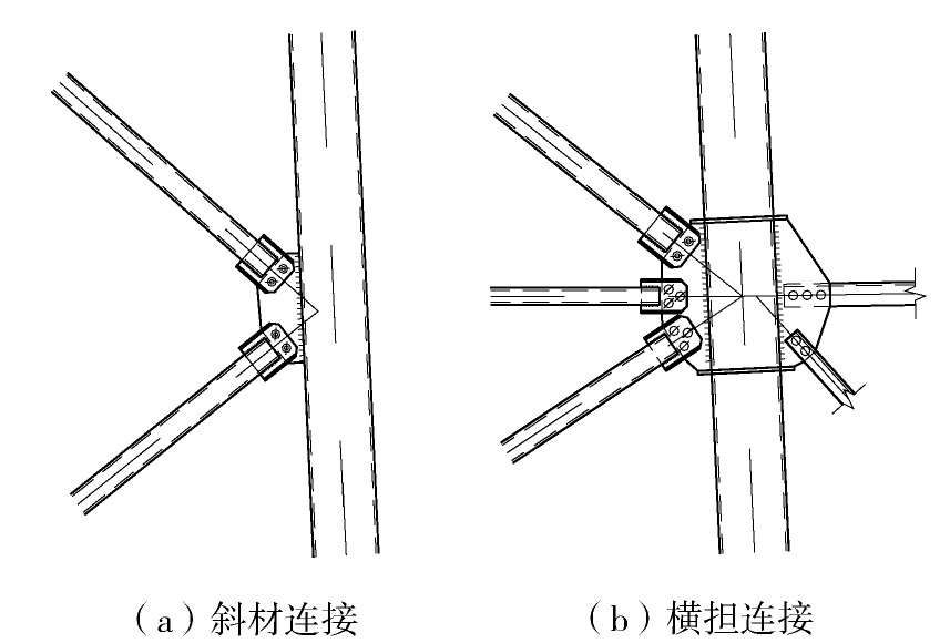
    1)变坡以上斜材采用偏心时,应考虑偏心节点产生的节点弯矩对主材控制应力的影响,建议偏心小于1/4管径或不偏心,偏心大小取决于杆件连接特点,如图3(a)所示,斜材偏心将减小节点板高度;如图3(b)所示,斜材与横担连接处,根据横隔面杆件和斜材角度,建议不偏心。

    Figure 3.  Connecting of brace member and main member above changing slope point

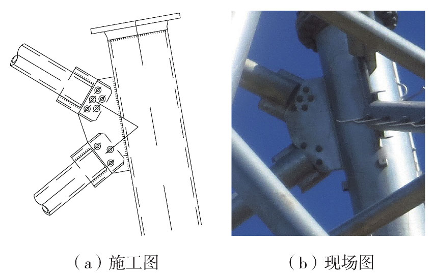
    2)变坡以下塔身斜材与塔身主材连接可采用偏心连接,主材控制应力基本不受影响,建议偏心不超过1/2主管径,图4为工程中采用节点偏心1/4主管径。

    Figure 4.  Connecting of brace member and main member under changing slope point

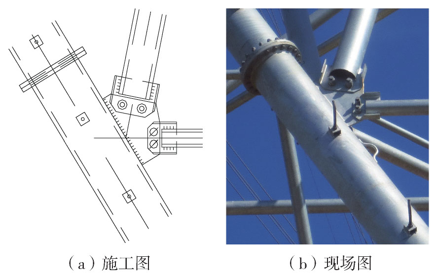
    3)辅助材与塔身主材或塔身斜材连接时,节点偏心不超过1/2主管径,如图5所示。

    Figure 5.  Connecting of auxiliary member and brace member

    4)设计中需控制斜材与水平面的夹角,塔身斜材与水平面的夹角取35°~45°为宜。夹角过大时,节点板的自由边长度lf与厚度t之比可能大于60 ;夹角过小时,节点板宽度可能较大。

    5)塔身斜材或辅助材偏心后,斜材控制应力基本不受影响,可减小节点板尺寸,但需验算节点板焊缝强度是否满足受力需求。

    6)为更好了解铁塔整体受力性能,建议做铁塔真型试验验证偏心节点钢管塔的安全可靠性。

  • 1)相比传统钢管塔无偏心节点的连接方式,采用偏心节点连接可以减小节点板尺寸,达到降低节点板重量和降低塔身风荷载,即可降低铁塔重量,具有一定的经济意义。

    2)变坡以上斜材偏心时,应考虑偏心产生的节点弯矩对主材控制应力的影响;变坡以下斜材偏心时,主材控制应力基本不受影响。

    3)辅助材与塔身主材或塔身斜材连接时,建议节点偏心1/2主管径。塔身斜材或辅助材偏心后,其自身控制应力基本不受影响,但需验算节点板焊缝强度是否满足受力需求。

    4)本文给出的钢管塔偏心节点计算和设计建议,简单易操作,可为工程提供参考。

Reference (10)

Catalog

    /

    DownLoad:  Full-Size Img  PowerPoint
    Return
    Return