

-
近些年全世界都在寻求新能源发展的方向与目标,尤其是欧洲已将海上风电作为新能源发展的主要方向之一[1]。2017年是中国海上风电创记录的一年,中国海上风电新增装机从2016年的0.61 GW增长到1.17 GW,预计到2020年底,我国海上风电装机约达到5 GW。这表明,我国海上风电已正式进入全新阶段,将拥有广阔的市场空间[2]。
与陆上风电相比,海上风况优于陆地,年利用小时长,风速更高,单机能量产出较大。近年来随着海上风电技术的发展,海上风电单机容量越来越大型化,浅海域风电场的建设远远不能满足风能发电的要求,风电场向深海的发展也成为一种必然趋势[3]。深海环境风浪大、地质条件复杂、软土地基分布广厚、水深变化大等恶劣自然条件对风机基础结构挑战巨大[4]。传统的单桩基础在单机容量大、大水深和深厚软基中基本没有设计条件[5];重力式基础遇到软基需要大开挖或地基处理,工程量巨大、不利于环保,且受冲刷严重不适合大水深[6];多桩承台基础施工工序多,海上现浇施工时间长,桩位定位困难,斜桩嵌岩施工难度大[7];多桩导管架基础适合任何水深,水阻力小,整体稳定性好,但水下定位和灌浆的难度较大,全钢结构造价高,目前在国内应用较少,成熟经验不多[8,9]。为了迎对国家海上风电快速发展的趋势,亟需开发新型的海上风电基础结构形式满足大水深和深厚软基的设计需求。
插入式大直径钢圆筒结构是近年来我国引入的新型海工结构,其特殊的结构型式和空间形态使其具有整体稳定性好、整体预制安装施工快速、对地基土要求不高等特点,只要底部插入一定硬度的持力层满足整体稳定性即可,适用于软基或土质变化较大的深海区域,在未来海洋工程中的应用前景广阔[10]。但其受力模式复杂,受力特性与整体稳定性因其空间形态、内部回填料物理力学指标、外荷载作用方式等不同而有较大差异。其应用目前在国际上也处于起步阶段,设计经验有限,仅日本的OCDI规范有关于插入式钢圆筒的设计规程,但OCDI仅针对埋深较浅且地基为砂土等特定条件下的钢圆筒计算,深埋插入式钢圆筒计算理论完全不同于传统结构型式,因此目前多采用数值模拟手段进行研究分析[11]。因此本文以某海上风电工程基础设计为算例,以PLAXIS 3D大型有限元软件为平台,对一种新型大直径钢圆筒组合导管架风机基础结构进行空间三维弹塑性数值模型分析研究,采用合理可行的本构类型以及简化形式模拟风机基础的整体稳定性,考虑钢圆筒与土体之间的共同作用,分析风机基础的内力与位移,再用ANSYS软件建实体模型计算极限荷载工况下各构件的应力,分析结果为今后新型海上风电基础形式的开发与研究提供参考依据。
HTML
-
某海上风电场示范项目,在受台风影响显著的海域试验5 MW大功率海上风力发电机组,探索风力发电机组基础新技术,为后续海上风电发展积累技术经验。风机安装轮毂高度90 m,工程等级为Ⅱ级,风电机组地基基础设计等级为Ⅰ级,相应结构安全等级为一级。场址内海域水深多大于20 m,地质条件和波浪条件如表1、表2所示。项目虽推荐高桩承台为风机基础结构,但鉴于示范风场区域软土分布广、持力层埋深变化大、风大浪大等恶劣自然环境条件导致承台受到的波浪浮托力和波浪力很大,桩基的水平力和拔桩力增大,设计桩长与实际桩长难以一致,增加海上打桩及现浇承台的施工难度,无法有效控制工期,因此需要深入探究新型海上风机基础结构替代方案的可能性。
土层名称 湿容重ρ/(kN·m-3) 压缩模量Es/MPa 承载力特征值f允/kPa 快剪 预制桩(钢管桩) 冲(钻)孔桩 抗拔系数λ 凝聚力c/kPa 内摩擦角φ/(°) 桩的极限侧阻力标准值qsik/kPa 桩的极限端阻力标准值qpk/MPa 桩的极限侧阻力标准值qsik/kPa 桩的极限端阻力标准值qpk/MPa ①淤泥 17.1 2.2 40~50 9 1.5 20 — 18 — 0.5 ②粉细砂 18.0 5.5 110~130 — 19 40 — 30 — 0.5 ③粉质粘土 19.5 4.5 110~130 25 12 50 — 45 — 0.6 ④中粗砂 18.5 7.0 150~180 — 22.5 70 5.0 55 1.2 0.6 ⑤泥质中细砂 18.5 4.5 150~170 — 21 60 — 48 — 0.5 ⑥粉质粘土 19.5 4.5 110~130 25 12 65 — 50 — 0.7 ⑦淤泥 18.2 2.2 50~60 11 2 30 — 25 — 0.5 ⑧泥质中粗砂 18.5 5.0 200~230 — 22.5 75 5.5 60 1.2 0.6 ⑨全风化岩体 19.5 6.0 220~250 12 23 90 — 80 — 0.7 ⑩散体状强风化岩体 21.5 10.0 250~300 14.5 27 120 9.0 100 3.0 0.6 Table 1.
Physical and mechanical indexes of each main soil layer in the project site 水深/m 平均波高 


平均周期 


平均波长 


H1%/m H4%/m H5%/m H13%/m 21.2 3.99 10.1 125.21 8.44 7.3 7.06 6.06 Table 2.
Design wave elements one time in 50 years
-
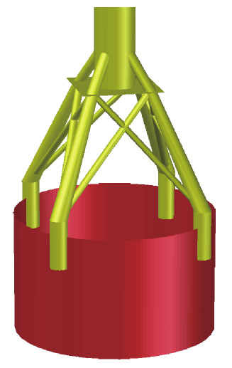
大直径钢圆筒组合导管架结构如图1所示,钢圆筒直径25 m,入土深度根据岩面高度的不同在15~30 m不等,上部构件是主要尺寸为直径1.5~2.2 m厚30 mm的钢管,出于大直径钢圆筒组合导管架结构自身的空间受力特性以及与筒内、筒外地基土体相互作用的复杂性,须以整体空间三维有限元模型才能真实合理地模拟各工况下上部风机荷载、波浪力等对新型基础结构的稳定性影响[12]。

Figure 1. 3D figure of the foundation structure with large-diameter steel cylinder combined jacket for offshore wind turbine
-
PLAXIS 3D是由荷兰PLAXIS B.V.公司推出的大型通用三维岩土有限元计算软件,现在已广泛应用于各种复杂岩土工程项目的数值分析中。以PLAXIS 3D为平台,以一个大直径钢圆筒基础及一组上部钢构件为模拟对象,模拟钢圆筒基础与土体之间的相互作用、筒身变形、筒体与上部构件力的传递以及上部构件的受力等,分析在极限工况以及正常使用工况下筒形基础的稳定性。
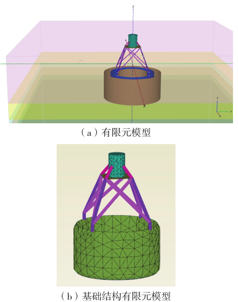
有限元模型如图2所示,为满足三维有限元的计算精度要求,土体计算范围在深度和长度方向相应扩大到一组风电基础计算区域的3~5倍。为了能较实际地模拟钢圆筒-地基土之间的相互作用,对土体采用实体单元模拟,对大直径钢圆筒结构采用板单元模拟,筒体与土体之间设置接触面单元,PLAXIS 3D中界面单元采用Goodman接触面单元考虑接触面变形的非线性特征,假定接触面上的法向应力和剪应力与法向相对位移和切向相对位移之间无交叉影响,模拟不同材料之间的相互滑移、脱离等力学现象。上部导管架钢构件采用梁单元模拟,法兰面以及塔筒采用板单元模拟。

Figure 2. Spatial 3D finite element model of the foundation structure with large-diameter steel cylinder combined jacket for offshore wind turbine
PLAXIS软件中的土体硬化模型Hardening soil model(HS)能够考虑土体刚度随应力状态的变化,其弹性部分采用了合理的双刚度,即加/卸载模量分别定义,且考虑了土体模量随应力增加而增大的特性[13]。塑性部分采用了非相关联流动法则和各向同性的硬化准则,可较好地描述曲线形式的应力应变关系和土体的剪胀性。本次分析软粘土、粉细砂和泥质砂层采用土体硬化HS本构模型,中粗砂层和岩体采用摩尔-库伦本构模型。
-
1)永久荷载:基础及其构件自重以及风机荷载竖向分项力等。风机各主要部分质量:轮毂质量43 t,叶片质量48 t(3片),发电机质量140 t,机舱质量45 t。塔筒总质量456 t。
2)风机荷载:风机基础通常按照风机厂家提供的极端荷载、正常运行荷载和疲劳荷载设计计算。作用在塔筒底部的风机荷载值根据风机制造厂商提供机型参数资料如表3所示。
工况名称 Fx/MN Fy/kN Fz/MN Mx/(MN· m) My/(MN· m) Mz/(MN· m) 正常运行荷载 1.049 9 -18.2 -7.347 4.910 6 83.459 2.721 2 极端荷载(无安全系数) -1.177 9 -136.5 -7.099 6 4.725 7 -126.667 3 -3.430 7 疲劳荷载 0.386 109 0.196 9.203 22.952 3.826 Table 3.
The load value acting on the bottom of the tower barrel 3)波浪力:根据海洋水文成果(表2),作用在风机基础结构上波浪力按港工相关规范计算。
4)水流荷载:流速按均匀分布考虑,平均流速大小为1.2 m/s,水流阻力系数Cw取0.73。
5)基础风荷载:按照50年一遇最大风速50 m/s计算风压,风荷载计算中根据结构实际情况确定对应的风压高度变化系数、风荷载体型系数和风振系数。
6)荷载分项系数与工况组合:基础结构安全等级为一级、二级的结构重要性系数分别为1.1和1.0,计算荷载组合如下:
(1)极端荷载工况计算内力时:1.2×永久荷载+1.5×极端风机荷载+1.5×50年一遇波浪力+1.5×水流力+1.4×基础风荷载。
(2)极端荷载工况稳定性分析时:1.0×永久荷载+1.0×极端风机荷载+1.0×50年一遇波浪力+1.0×水流力+1.0×基础风荷载。
(3)正常使用工况稳定性分析时:1.0×永久荷载+1.0×正常风机荷载+1.0×50年一遇波浪力+1.0×水流力+1.0×基础风荷载。
-
模型的位移边界条件:四个侧面约束其法向位移,底面约束其三个方向的位移;排水边界条件:底面及四个侧面均为不排水边界,顶面为排水边界。
2.1 空间三维有限元模型与土体本构模型
2.2 荷载条件
2.3 边界条件
-
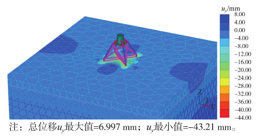
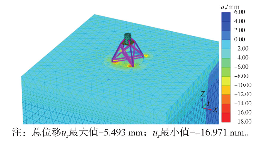
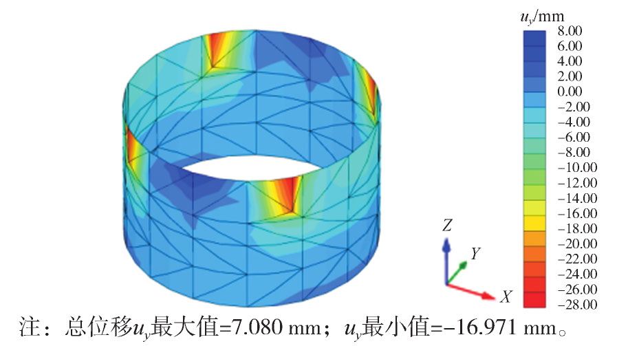
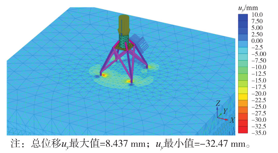
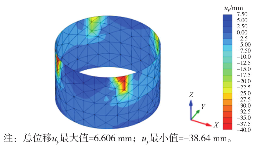
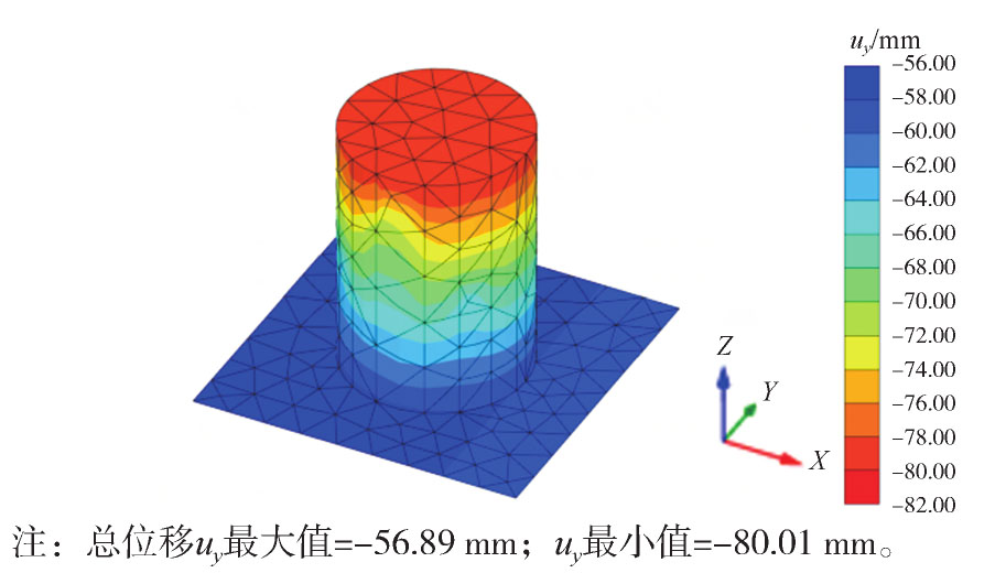
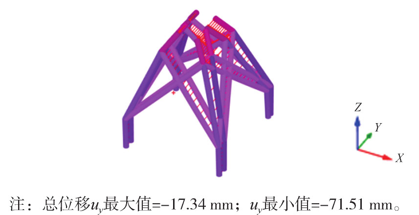
图3,图4,图5,图6,图7,图8分别为大直径钢圆筒组合导管架海上风电基础结构整体位移云图和各构件变位、内力云图,三维弹塑性有限元模型强度折减法算出的整体稳定安全系数为2.033,满足整体稳定要求。极端荷载工况下进行结构稳定性分析时土体强度没有进行折减。

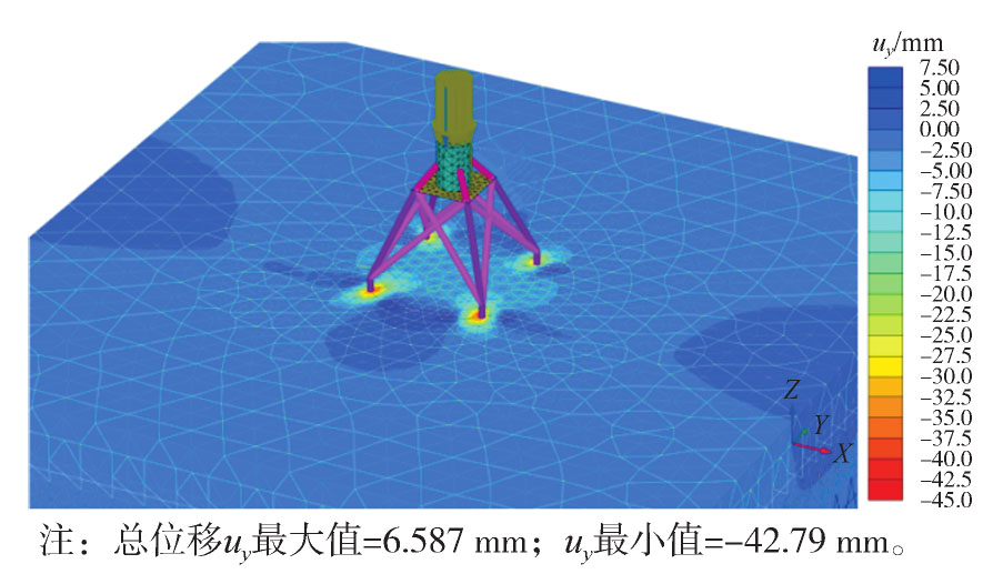
Figure 3. Horizontal displacement of soil under extreme load conditions

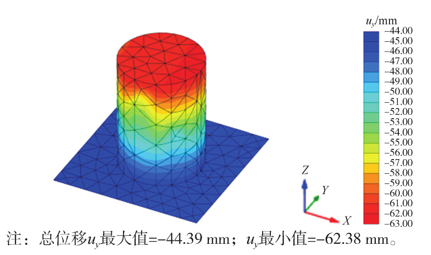
Figure 4. Soil settlement-deformation under extreme load conditions

Figure 5. Displacement of steel cylinder structure under extreme load conditions

Figure 6. Horizontal displacement of the flange and tower drum under extreme load conditions

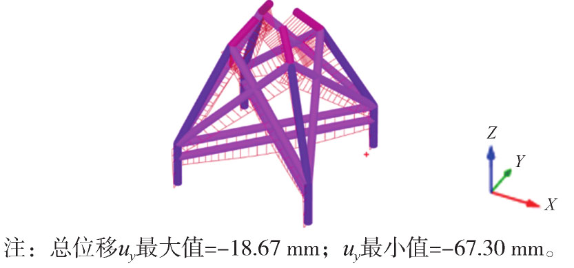
Figure 7. Horizontal displacement of the upper jacket under extreme load conditions

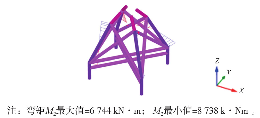
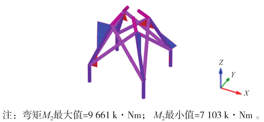
Figure 8. Structural internal force of the upper jacket under extreme load conditions
-
图9,图10,图11,图12,图13,图14分别为大直径钢圆筒组合导管架海上风电基础结构整体位移云图和各构件变位、内力云图,三维弹塑性有限元模型强度折减法算出的整体稳定安全系数为1.981,满足整体稳定要求。正常使用工况下考虑土体循环荷载下疲劳,泥面下10 m以上土体参数乘系数0.33,10~20 m土体参数乘系数0.66,因此算出来的位移和内力基本与极限工况下稳定性计算结果相近,略偏大于极限工况。

Figure 9. Horizontal displacement of soil under normal load conditions

Figure 10. Soil settlement-deformation under normal load conditions

Figure 11. Displacement of steel cylinder structure under normal load conditions

Figure 12. Horizontal displacement of the flange and tower drum under normal load conditions

Figure 13. Horizontal displacement of the upper jacket under normal load conditions

Figure 14. Structural internal force of the upper jacket under normal load conditions
从分析结果来看当轮毂高度为90 m时,大直径钢圆筒组合导管架海上风机基础沉降≤100 mm,正常运行工况基础顶面(塔筒底部)的最大倾斜率为tan θ≤4×10⁻³,极限运行工况基础顶面(塔筒底部)的最大倾斜率为tanθ≤8.7×10⁻³(即θ≤0.25°),结构满足变形要求;模型中部分构件内力偏大,超过允许值,但是由于PLAXIS 3D中构件采用了梁单元和板单元进行模拟,并不能反映各构件及连接处的真实应力,因此用大型通用结构有限元软件ANSYS建实体模型计算极限荷载工况下各构件的应力。
3.1 极限荷载工况下模型稳定性计算结果
3.2 正常使用工况下模型稳定性计算结果
-
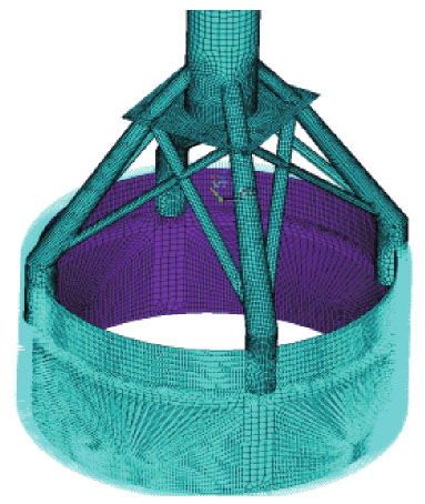
底部钢圆筒直径25 m,高15 m,顶部6 m高度范围内壁厚50 mm,剩余区域钢圆筒壁厚30 mm;上部杆件直径从2.2 m到1.0 m不等,连接杆壁厚50 mm。通过有限元软件ANSYS对风机基础结构内力进行了计算。有限元模型中采用壳单元SHELL43模拟基础结构部分。结构与地基土的相互作用根据m法计算原理,采用线性弹簧单元COMBIN14模拟。有限元计算模型如图15所示。

Figure 15. Internal force analysis and calculation model of the foundation structure with large-diameter steel cylinder combined jacket for offshore wind turbine
-
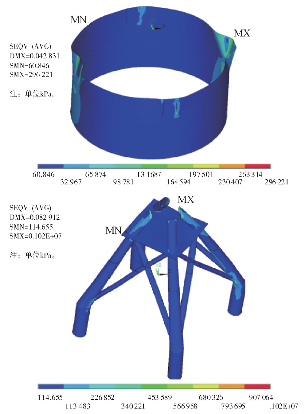
通过计算,得到结构各部内力如图16所示。从结构内力计算结果看,钢圆筒上MISES应力最大值出现在上部杆件与大圆筒的连接处,最大应力值为296.2 MPa;上部杆件MISES应力最大值出现在杆件与塔筒的连接处,因为模型采用了弹性模型,应力值无法通过塑性区的扩散而减小,局部应力集中,最大应力值为1.02 GPa,模型的强度不满足要求,需要进行局部构造加强。

Figure 16. MISES stress distribution of the foundation structure with large-diameter steel cylinder combined jacket for offshore wind turbine
4.1 ANSYS有限元模型
4.2 内力计算结果
-
1)通过PLAXIS 3D空间三维弹塑性有限元建模分析结果表明:大直径钢圆筒组合导管架海上风机基础结构方案整体稳定性较好,沉降和水平位移均符合规范要求。
2)由于软土地基深厚,地基承载力较弱,法兰和塔筒底部的位移最大达到8 cm,建议在筒内、筒外增加一定置换率的水泥土搅拌桩或是挤密砂桩,进行小范围的土体加固后即可控制位移。
3)通过ANSYS软件三维实体建模分析大直径钢圆筒组合导管架海上风机基础结构内力结果表明,在上部导管架结构和钢圆筒相连接处有小部分区域应力集中,通过增加接触面积可以降低局部应力。
4)在结构内力计算结果中,法兰与塔筒底部有很大的局部应力集中点,可通过内部增加纵横肋板进行结构应力增强。
关于局部构造措施需要通过施工和设计计算分析共同探讨解决,关于建造和施工是此新型风机基础结构下一步工作内容的重点。

 DownLoad: