• Peer Review
  • Non-profit
  • Global Open Access
  • Green Channel for Rising Stars
Volume 5 Issue 4
Jul.  2020
Turn off MathJax
Article Contents

Fuquan HU, Pengfei LI, Zheng HE. Buckling Impact Analysis of Cylinderial Shells with Opening and Reinforcement Under Axial Compression[J]. SOUTHERN ENERGY CONSTRUCTION, 2018, 5(4): 60-65. doi: 10.16516/j.gedi.issn2095-8676.2018.04.009
Citation: Fuquan HU, Pengfei LI, Zheng HE. Buckling Impact Analysis of Cylinderial Shells with Opening and Reinforcement Under Axial Compression[J]. SOUTHERN ENERGY CONSTRUCTION, 2018, 5(4): 60-65. doi: 10.16516/j.gedi.issn2095-8676.2018.04.009

Buckling Impact Analysis of Cylinderial Shells with Opening and Reinforcement Under Axial Compression

doi: 10.16516/j.gedi.issn2095-8676.2018.04.009
  • Received Date: 2017-08-24
  • Rev Recd Date: 2017-10-17
  • Publish Date: 2018-12-25
  •   [Introduction]  The early buckling theory of cylindrical shells under axial compression has a great deviation from the experimental results, there are many factors that lead to differences, the initial geometrical defect is the main factor that produces the difference.  [Method]  In this paper, a special axial compression buckling test platform was used to scan the three-dimensional actual topography of the shell by using a laser displacement sensor, and the axial compression buckling test was carried out by the hydraulic device.  [Results]  The results show that the critical load of axial buckling of cylindrical shells is reduced by opening holes, and the buckling load of the cylindrical shell is improved by inserting a circular tube in the opening hole. Based on the measured data of shell topography, a finite element model is established, and the nonlinear buckling finite element analysis of cylindrical shells, cylindrical shells with openings and reinforcement is carried out by Abaqus.  [Conclusion]  The law of simulation is consistent with the experiment, the axial load of the shell is increased firstly and then decreased, the critical load of the axial compressive buckling of the cylindrical shell with opening is the least, the critical load of the cylindrical shell with the reinforcement is the second larger, the buckling critical load of the cylindrical shell without openings is the largest. The critical load simulation values of different shells are compared with the experimental values, in which the minimum relative error is only 13.8%. This method can be used to predict the critical buckling load of the shell, and it is of reference value to the buckling design of the shell.
  • [1] 赵阳,滕锦光. 轴压圆柱钢薄壳稳定设计综述 [J]. 工程力学,2003,20(6):116-126.

    ZHAO Y,TENG J G. Stability design of axially compressed thin steel cylindrial shells [J]. Engineering Mechanics,2003,20(6):116-126.
    [2] 祝恩淳,MANDAL P,CALLADINE C R. 轴压圆柱薄壳的屈曲分析.工程土木工程学报 [J]. 2001,34(3):18-28.

    ZHU E C,MANDAL P,CALLADINE C R. Analysis of buckling of thin cylindrical shells under axial compression [J]. China Civil Engineering Journal,2001,34(3):18-28.
    [3] HUTCHINSON J W,BUDIANSKY B. Dynamic buckling estimates [J]. AIAA Journal,1966,4(3):525-530.
    [4] LOCKHART D F. Dynamic buckling of a damped externally pressurized imperfect cylindrical shell [J]. Journal of Applied Mechanics,1979,46(2):372-376.
    [5] LOCKHART D F. Postbucklingdynamic behavior of periodically supported imperfect shells [J]. International Journal of Non-Linear Mechanics,1982,17(3):165-174.
    [6] LOCKHART D F,AMAZIGO J C. Dynamic buckling of externally pressurized imperfect cylindrical shells [J]. Journal of Applied Mechanics,1975,42(2):316-320.
    [7] LEE D S. Nonlinear dynamic buckling of orthotropic cylindrical shells subjected to rapidly applied loads [J]. Journal of Engineering Mathematics,2000,38(2):141-154.
    [8] KIM S E,KIM C S. Buckling strength of the cylindrical shell and tank subjected to axially compressive loads [J]. Thin-walled Structures,2002,40(4):329-353.
    [9] BLACHUT J. Buckling of axially compressed cylinders with imperfect length. Computer and Structures [J]. 2010,88(5-6):365-374.
    [10] TENNYSON C R. A note on the classical buckling load of circular cylindrical shells under axial compression [J]. AIAA Journal,1963,1(2):475.
    [11] TENNYSON R. Buckling modes of circular cylindrical shells under axial compression [J]. AIAA Journal,1969,7(8):1481-1487.
    [12] MANDAL P,CALLADINE C. Buckling of thin cylindrical shells under axial compression [J]. International Journal of Solids and Structures,2000,37(33):4509-4525.
    [13] HORNUNG U,SAAL H. Buckling Loads of tank shells with imperfections [J]. International Journal of Non-linear Mechanics,2002,37(4):605-621.
    [14] 王绍杰. 钢骨混凝土倒T型梁受力性能的研究 [J]. 工程力学,2003,12(增刊1):652-655.

    WANG S J. Research on the performance of T type steel reinforced concrete beams [J]. Engineering Mechanics,2003,12(Supp.1):652-655.
    [15] 陈丽敏,陈思作. 轴压圆柱壳的局部稳定数值分析与试验研究 [J]. 工业建筑,2005,35(10):69-72.

    CHEN L M,CHEN S Z. Numerical analysis and experimental study on local stabiity of cylindrical shell under axial loads [J]. Industrial Construction,2005,35(10):69-72.
    [16] 宋晓飞,郑小华,陈立飞. 接管壁厚度变化对圆柱壳开孔接管应力集中系数的影响 [J]. 山东化工,2013,42(5):122-124.

    SONG X F,ZHENG X H,CHEN L F. The influence of the wall thickness on the stress concentration factor of the nozzle of the cylindrical shell [J]. Shandong Chemical Industry,2013,42(5):122-124.
    [17] 李玉坤,何茂林,段冠. 大型油罐罐壁开孔补强应力分析 [J]. 油气田地面工程,2009,28(9):27-29.

    LI Y K,HE M L,DUAN G. Stress analysis of reinforcement for opening in large oil tank wall [J]. Oil and Gas Field Surface Engineering,2009,28(9):27-29.
    [18] 管凤阶. 大型钢制焊接储罐设计 [J]. 油气田地面工程,2004,23(1):38-39.

    GUAN F J. Design of large steel welded tank [J]. Oil and Gas Field Surface Engineering,2004,23(1):38-39.
    [19] 李玉坤,孙文红,李春,等. 大型立式储罐罐壁开孔补强应力分析 [J]. 压力容器,2012,29(10):237-240.

    LI Y K,SUN W H,LI C,et al. Stress analysis of reinforcement for openings in large vertical storage tanks′ skin [J]. Pressure Vessel,2012,29(10):237-240.
    [20] 李晓蒙,何铮. 核电厂非能动安全壳冷却系统储水箱的振动特性分析 [J]. 南方能源建设,2015,2(4):102-106.

    LI X M,HE Z. Dynamic characteristic analysis of the passive containment cooling system water tank of nuclear power plants [J]. Southern Energy Construction,2015,2(4):102-106.
    [21] 李晓蒙. 钢制安全壳的抗震可靠性计算研究 [J]. 南方能源建设,2016,3(3):79-84.

    LI X M. Study on the seismic reliability of steel containment [J]. Southern Energy Construction,2016,3(3):79-84.
    [22] ZHAO Y,TENG J G. Buckling experiments on steel silo transition junctions I: experimental results [J]. Journal of Constructional Steel Research,2004,60(12):1783-1801.
  • 通讯作者: 陈斌, bchen63@163.com
    • 1. 

      沈阳化工大学材料科学与工程学院 沈阳 110142

    1. 本站搜索
    2. 百度学术搜索
    3. 万方数据库搜索
    4. CNKI搜索

Figures(10)  / Tables(1)

Article Metrics

Article views(228) PDF downloads(12) Cited by()

Related

Buckling Impact Analysis of Cylinderial Shells with Opening and Reinforcement Under Axial Compression

doi: 10.16516/j.gedi.issn2095-8676.2018.04.009

Abstract:   [Introduction]  The early buckling theory of cylindrical shells under axial compression has a great deviation from the experimental results, there are many factors that lead to differences, the initial geometrical defect is the main factor that produces the difference.  [Method]  In this paper, a special axial compression buckling test platform was used to scan the three-dimensional actual topography of the shell by using a laser displacement sensor, and the axial compression buckling test was carried out by the hydraulic device.  [Results]  The results show that the critical load of axial buckling of cylindrical shells is reduced by opening holes, and the buckling load of the cylindrical shell is improved by inserting a circular tube in the opening hole. Based on the measured data of shell topography, a finite element model is established, and the nonlinear buckling finite element analysis of cylindrical shells, cylindrical shells with openings and reinforcement is carried out by Abaqus.  [Conclusion]  The law of simulation is consistent with the experiment, the axial load of the shell is increased firstly and then decreased, the critical load of the axial compressive buckling of the cylindrical shell with opening is the least, the critical load of the cylindrical shell with the reinforcement is the second larger, the buckling critical load of the cylindrical shell without openings is the largest. The critical load simulation values of different shells are compared with the experimental values, in which the minimum relative error is only 13.8%. This method can be used to predict the critical buckling load of the shell, and it is of reference value to the buckling design of the shell.

Fuquan HU, Pengfei LI, Zheng HE. Buckling Impact Analysis of Cylinderial Shells with Opening and Reinforcement Under Axial Compression[J]. SOUTHERN ENERGY CONSTRUCTION, 2018, 5(4): 60-65. doi: 10.16516/j.gedi.issn2095-8676.2018.04.009
Citation: Fuquan HU, Pengfei LI, Zheng HE. Buckling Impact Analysis of Cylinderial Shells with Opening and Reinforcement Under Axial Compression[J]. SOUTHERN ENERGY CONSTRUCTION, 2018, 5(4): 60-65. doi: 10.16516/j.gedi.issn2095-8676.2018.04.009
  • 圆柱壳在工业及许多领域都有广泛的应用,轴压圆柱壳的屈曲问题一直是壳体稳定研究中最为活跃的课题之一[1,2]。Hutchinson、Lockhart、Doo-Sung lee等许多学者[3,4,5,6,7,8,9,10,11,12,13]对圆柱壳屈曲进行了研究。早期的轴压圆柱壳和均匀外压薄球壳的试验临界压力,只有经典线性理论预值的1/5~1/2,并且试验结果离散性很大,轴压屈曲在理论值与试验之间常常存在一个不被人接受的大“误差”[14,15]。各国学者进行了大量的研究试图解释轴压圆柱壳试验值与理论解之间的巨大差异,广为接受的结论:产生该差异的根本原因在于壳体中存在初始几何缺陷[1]

    实际工程设计通常会在圆柱壳上开各种孔,造成了几何结构不连续,不仅加大了开孔边缘的应力集中,而且削弱了壳体结构强度,降低了壳体的承载力[16,17,18]。通常会采用补强的方法提高承载力,补强就是在开孔的周围增加因开孔被削弱的金属量,降低孔周围局部区域的应力,由于应力集中只发生在孔的附近,在几倍孔径以外,应力几乎不受孔的影响[19]

    安全壳[20,21]是压水堆的关键设备,是反应堆的最后一道安全屏障,其内层钢制安全壳是一种典型的薄壁压力容器,体积大、厚度薄,包括上、下封头与圆柱壳段,其中有许多开孔、接管、贯穿件等。本文以安全壳的圆柱壳段为研究模型,对开孔和补强的圆柱壳进行轴压屈曲试验和非线性有限元分析。缩比实验的设计与实现有助于获得合适的有限元模型。近年来,钢制壳体的屈曲试验得到了广泛的开展[22],但试验模型较小,与安全壳的径厚比相差甚远,亦缺少人造局部缺陷和补强等因素。

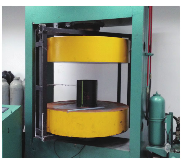
  • 试验采用浙江大学的轴压屈曲试验专用平台,平台由具有中心孔的固定工作台和活动工作台组成,活动工作台与液压装置相连,用于压缩试验件,如图1所示。测试仪器主要有称重传感器、激光位移传感器、DH5932数据采集记录分析系统、双/单向应变片等。

    Figure 1.  Photo of test platform

  • 试验件材料均为B340钢,直径均为1 000 mm,高均为600 mm,厚均为1.2 mm,如图2所示。开孔圆柱壳的开孔直径为150 mm,孔中心在圆柱壳高300 mm处。含补强件圆柱壳的补强件(圆管)内径为150 mm,厚为3.5 mm,长为50 mm,补强件中心在圆柱壳高300 mm处。壳体上下边均用类似于法兰的带槽环形钢环固定,以增加壳体稳定性,便于运输及轴压试验。

    Figure 2.  Photo of experiment models

  • 1)试验件几何形貌测量:轴压屈曲试验前,对试验件的几何形貌进行测量。测量方法:把激光位移传感器调到合适的位置固定在屈曲平台的旋转框架上,通过步进电机带动旋转框架绕试验件做圆周运动,多次测量得到试验件外围形貌数据。

    2)轴压屈曲试验:几何形貌扫描后在试验件外表面布置轴向或环向应变片,测量轴压屈曲过程中的各测点应变变化情况。轴压屈曲试验的轴向压力由液压装置提供,轴压数据由称重传感器得到。轴压屈曲过程中同步采集轴压和应变数据。

  • 试验得到圆柱壳、开孔圆柱壳、含补强件圆柱壳的轴向压力随时间变化关系如图3所示。轴压曲线先增大后减小。轴压峰值分别为57.46 t、45.47 t、55.66 t,约为149.4 MPa、118.3 MPa、144.8 MPa。

    Figure 3.  The axial pressure curve of different cylindrical shells

    由此可知,开孔圆柱壳屈曲临界载荷最小,含补强件的圆柱壳次之,未开孔的圆柱壳临界载荷最大。说明开孔降低了壳体屈曲临界载荷,补强提高了壳体屈曲临界载荷。

    屈曲后的圆柱壳试件、开孔圆柱壳试件、含补强件圆柱壳试件,分别如图4(a)图4(b)图4(c)所示,圆柱壳和开孔圆柱壳屈形状均呈菱形。

    Figure 4.  The buckling photo of different cylindrical shells

    测得圆柱壳上排四个测点的轴向应变随时间变化关系如图5所示。

    Figure 5.  Strain curve of the cylindrical shell

    压应变随轴压增大而增大,屈曲后应变发生突变,之后表现为拉应变。

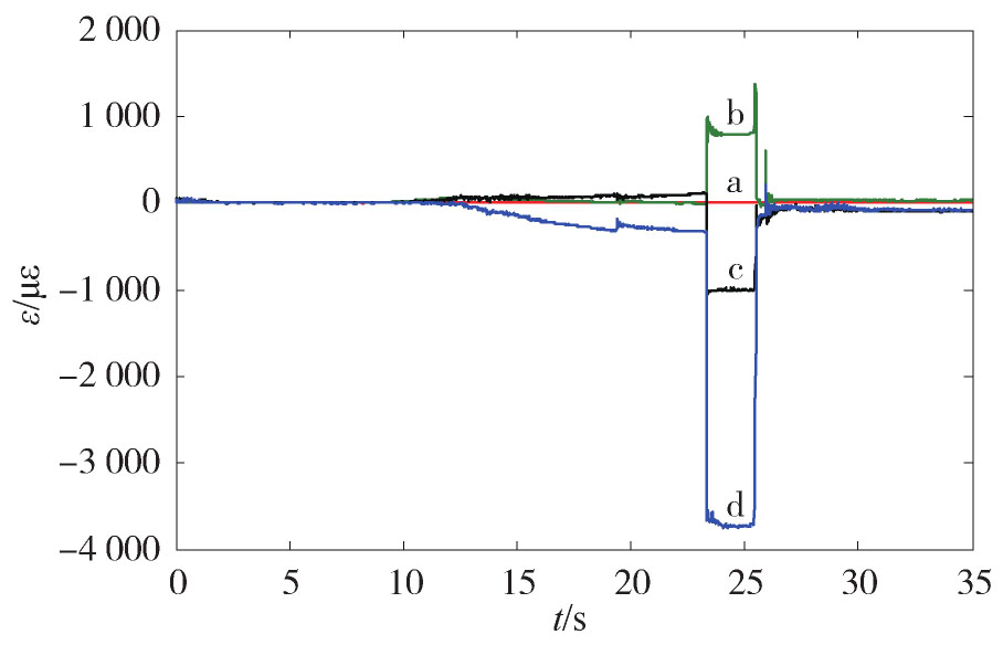
    测得开孔圆柱壳孔上边测点和孔中心高度左边测点的轴向及环向应变随时间变化曲线如图6所示。其中应变片1测孔上边测点的轴向应变,应变片2测孔上边测点的环向应变,应变片3测孔左边测点的轴向应变,应变片4测孔左边测点的环向应变。屈曲后各测点处应变出现了突变(应变片1除外),孔上边测点轴向应变片1应变变化不明显,因为下方是圆孔,轴向无支撑反力,但环向应变片2应变变化很明显。孔左边测点轴向应变片3和环向应变片4变化规律刚开始不一样,屈曲后出现突变,变化规律一致,但环向应变比轴向应变大,开孔改变了壳体应力分布。孔附近发生了明显屈曲。

    Figure 6.  Strain curve of the cylindrical shell with opening

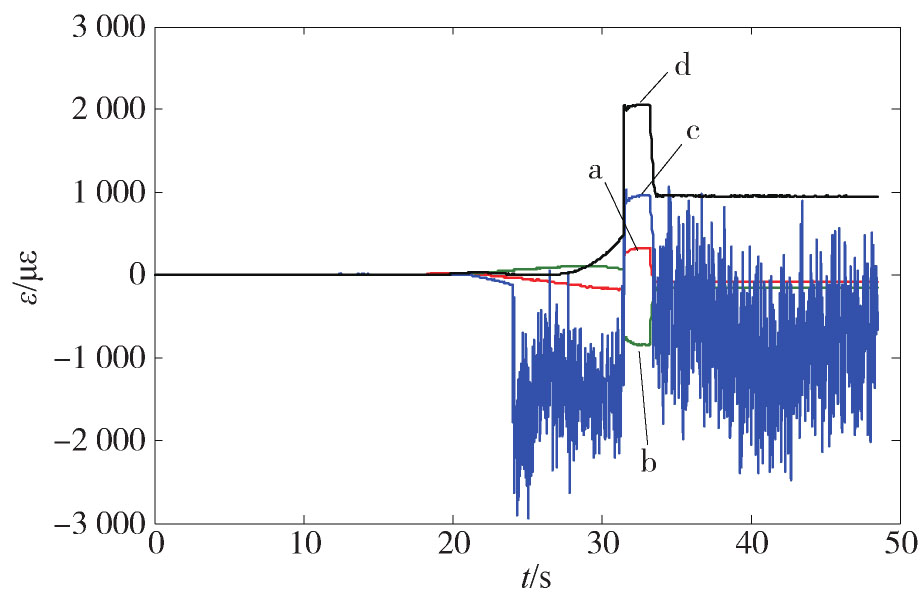
    测得补强件中心高度左边测点和上边测点的轴向与环向应变随时间变化曲线如图7所示。其中应变片3读数不理想,可能出现了松动。屈曲后应变出现了突变,与开孔圆柱壳应变变化不同,补强后改变了应力分布。

    Figure 7.  Strain curve of the cylindrical shell with reinforcement

  • 利用几何形貌测量数据建立有限元模型,本文利用Abaqus进行模拟分析,采用非线性稳定算法,通过施加人工阻尼来计算壳体轴压屈曲临界载荷,其中边界条件为圆柱壳下端面节点固支,限制上端面节点除轴向平动自由度以外的所有自由度。载荷通过定义带参考点控制的离散刚体来模拟压头,刚体与圆柱壳上端面之间定义接触实现轴向载荷传递,并通过参考点的反作用力来获取轴压屈曲临界载荷。

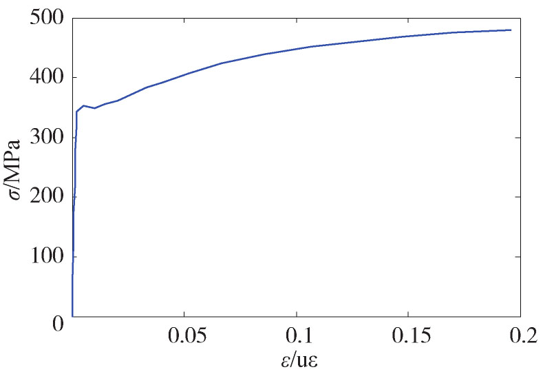
    通过拉伸试验获取材料的真实数据,得到的应力-应变曲线如图8所示。试验得到弹性模量E= 201.5 GPa,σy=355.7 MPa。

    Figure 8.  The stress-strain curve of B340 steel

    利用Abaqus进行非线性分析要用到材料的塑性特性,可使用以下关系计算塑性应变:

    式中:εpl为塑性应变;εreal为真实应变;E为弹性模量。

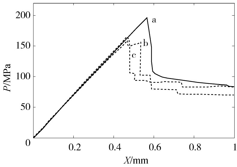
    模拟得到圆柱壳、开孔圆柱壳、含补强件圆柱壳的轴向压力与轴向位移变化关系如图9所示,轴压曲线先增大后减小。轴压峰值分别为195.4 MPa、158.4 MPa、164.8 MPa。

    Figure 9.  Relationship between axial stress and axial displacement

    由此可知,开孔圆柱壳屈曲临界载荷最小,含补强件的圆柱壳次之,未开孔的圆柱壳临界载荷最大。

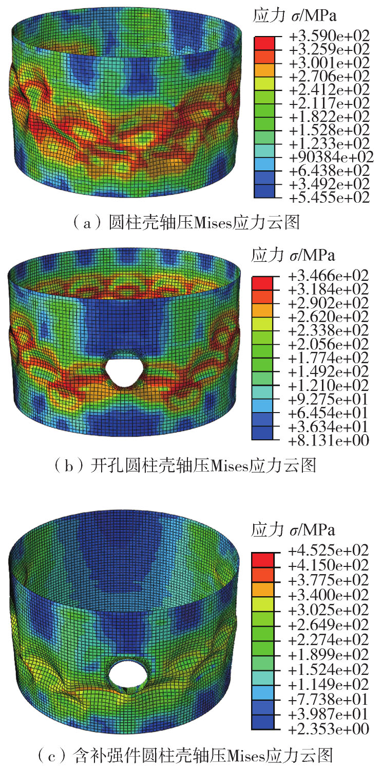
    圆柱壳、开孔圆柱壳和含补强件圆柱壳轴压屈曲Mises应力云图,分别如图10(a)、(b)、(c)所示,壳体发生了明显屈曲。

    Figure 10.  The mises stress nephogram of cylindrical shells

  • 对前面所述的各试验结果与模拟结果进行比较可知,试验与模拟得到的轴向压力均先增大后减小。轴压圆柱壳具有很强的非线性,从而导致圆柱壳在达到峰值荷载后承载力急剧下降,轴压圆柱壳的后屈曲性质是不稳定的,且很小的几何缺陷就会极大地降低其承载力[2]。不同壳体屈曲临界载荷值如表1所示。试验与模拟均是临界载荷值开孔圆柱壳最小,含补强件圆柱壳次之,圆柱壳最大。说明开孔降低了圆柱壳屈曲临界载荷,通过补强可以提高其屈曲临界载荷。

    类型 模拟值/MPa 试验值/MPa 相对误差/%
    圆柱壳 195.4 149.4 30.8
    开孔圆柱壳 158.4 118.3 33.9
    含补强件圆柱壳 164.8 144.8 13.8

    Table 1.  Comparison between simulation and test

    圆柱壳轴压屈曲临界载荷试验值与模拟值偏差30.8%,开孔圆柱壳轴压屈曲临界载荷试验值与模拟值偏差33.9%,含补强件圆柱壳轴压屈曲临界载荷试验值与模拟值偏差13.8%。试验结果比模拟结果小,可能的原因有以下几种:(1)由于圆柱壳试验件通过焊接而成,有一条竖向焊缝的影响,采用这类工艺制作完成的圆柱壳主要存在非对称的初始缺陷[1]以及材料本身缺陷;(2)壳体不直度造成荷载偏心。

  • 本文利用轴压屈曲试验平台进行了圆柱壳、开孔圆柱壳、含补强件圆柱壳轴压屈曲试验,试验结果表明:轴压屈曲临界载荷开孔圆柱壳最小,含补强件圆柱壳次之,圆柱壳最大,与模拟结果规律一致。圆柱壳开孔导致轴压临界载荷下降,可通过补强方法提高临界载荷。可为壳体屈曲设计分析提供参考价值。

Reference (22)

Catalog

    /

    DownLoad:  Full-Size Img  PowerPoint
    Return
    Return