• Peer Review
  • Non-profit
  • Global Open Access
  • Green Channel for Rising Stars
Volume 5 Issue 4
Jul.  2020
Turn off MathJax
Article Contents

Hao ZHANG, Wei ZHANG, Lijuan LU, Guojun TIAN. Research on the Engineering Application of Prefabricated Optical Cable in Standard Distribution Substation[J]. SOUTHERN ENERGY CONSTRUCTION, 2018, 5(4): 117-123. doi: 10.16516/j.gedi.issn2095-8676.2018.04.018
Citation: Hao ZHANG, Wei ZHANG, Lijuan LU, Guojun TIAN. Research on the Engineering Application of Prefabricated Optical Cable in Standard Distribution Substation[J]. SOUTHERN ENERGY CONSTRUCTION, 2018, 5(4): 117-123. doi: 10.16516/j.gedi.issn2095-8676.2018.04.018

Research on the Engineering Application of Prefabricated Optical Cable in Standard Distribution Substation

doi: 10.16516/j.gedi.issn2095-8676.2018.04.018
  • Received Date: 2017-12-14
  • Rev Recd Date: 2018-06-23
  • Publish Date: 2018-12-25
  •   [Introduction]  In order to realize standardized application and engineering popularization of prefabricated optical cable in standard distribution substation, it is necessary to study the project application scheme and engineering implementation problems of prefabricated optical cable.  [Method]  Based on the engineering application and demand of prefabricated optical cable in standard distribution substation, this paper compared the engineering application schemes with the structural type, optical cable type and prefabrication mode of prefabricated optical cable, it also studied some common problems and its solutions such as laying, attenuation control and residual length control.  [Results]  This paper unifies the structural type, optical cable type and prefabrication mode of prefabricated optical cable, solves the problems of cable laying, attenuation control and redundancy control length. It can shorten the construction period and save the investment, improve the applicability and economy of prefabricated optical cable in standard distribution substation.  [Conclusion]  Combining with the results of this paper, the standard distribution substation can choose the applicable project application scheme and project implementation scheme according the project scale and equipment layout and realize the modular installation and wiring of the whole station optical cable.
  • [1] State Grid Corporation of China. Technical guide for construction of standard delivery smart substation:Q/GDW 11152—2014 [S]. Beijing:China Electric Power Press,2014.
    [2] 高美金,傅旭华. 标准配送式变电站的特点与建设 [J]. 浙江电力,2014,33(3):31-34+62.

    GAO M J,FU X H. Characters and construction of standard distribution-based substations [J]. Zhejiang Electric Power,2014,33(3):31-34+62.
    [3] 朱秀琴,黄卫平. 智能变电站预制光缆应用方案研究 [J]. 能源与环境,2016(4):26-27+31.

    ZHU X Q,HUANG W P. Research on the application of prefabricated optical cable for smart substation [J]. Energy and Environment,2016(4):26-27+31.
    [4] State Grid Corporation of China. The technical specification for prefabricated optic cable in smart substation:Q/GDW 11155—2014 [S]. Beijing:China Electric Power Press,2014.
    [5] 张维,张浩,鲁丽娟,等. 智能交流变电站预制光缆针脚定义应用研究 [J]. 南方能源建设,2016,3(增刊1):116-121.

    ZHANG W,ZHANG H,LU L J,et al. Research on the application of the pin definition of prefabricated optical cable in smart substation [J]. Southern Energy Construction,2016,3(Supp.1):116-121.
    [6] 宋璇坤,闫培丽,吴蕾,等. 能变电站试点工程关键技术综述 [J]. 电力建设,2013,34(7):10-16.

    SONG X K,YAN P L,WU L,et al. Review of key technology for smart substation pilot projects [J]. China Electric Power,2013,34(7):10-16.
    [7] 苏麟,石慧,王爱民,等. 预制光缆在智能变电站应用技术研究 [J]. 中国电业(技术版),2014(9):64-67.

    SU L,SHI H,WANG A M,et al. Research on application technology of prefabricated optical cable in smart substation [J]. China Electric Power (Technical Version),2014(9):64-67.
    [8] 王丹,贾云辉,保玉玮. 智能变电站光缆两端预制方法的探讨 [J]. 通讯世界,2014(5):62-63.

    WANG D,JIA Y H,BAO Y W. Discussion on double side prefabrication method of optical cable in smart substation [J]. Telecom World,2014(5):62-63.
    [9] 高升. 预制式光缆在智能变电站的应用研究 [J]. 福建建设科技,2015(1):67-68.

    GAO S. Prefabricated optical fiber cable application research in smart substation [J]. Fujian Construction Technology,2015(1):67-68.
    [10] 丁腾波,李慧. 基于预制光缆的智能变电站户外组网方案 [J]. 电力建设,2013,34(2):50-54.

    Ding T B,LI H. Outdoor network scheme of smart substation based on prefab optical fiber cable [J]. Electric Power Construction,2013,34(2):50-54.
  • 通讯作者: 陈斌, bchen63@163.com
    • 1. 

      沈阳化工大学材料科学与工程学院 沈阳 110142

    1. 本站搜索
    2. 百度学术搜索
    3. 万方数据库搜索
    4. CNKI搜索

Figures(5)  / Tables(3)

Article Metrics

Article views(236) PDF downloads(15) Cited by()

Related

Research on the Engineering Application of Prefabricated Optical Cable in Standard Distribution Substation

doi: 10.16516/j.gedi.issn2095-8676.2018.04.018

Abstract:   [Introduction]  In order to realize standardized application and engineering popularization of prefabricated optical cable in standard distribution substation, it is necessary to study the project application scheme and engineering implementation problems of prefabricated optical cable.  [Method]  Based on the engineering application and demand of prefabricated optical cable in standard distribution substation, this paper compared the engineering application schemes with the structural type, optical cable type and prefabrication mode of prefabricated optical cable, it also studied some common problems and its solutions such as laying, attenuation control and residual length control.  [Results]  This paper unifies the structural type, optical cable type and prefabrication mode of prefabricated optical cable, solves the problems of cable laying, attenuation control and redundancy control length. It can shorten the construction period and save the investment, improve the applicability and economy of prefabricated optical cable in standard distribution substation.  [Conclusion]  Combining with the results of this paper, the standard distribution substation can choose the applicable project application scheme and project implementation scheme according the project scale and equipment layout and realize the modular installation and wiring of the whole station optical cable.

Hao ZHANG, Wei ZHANG, Lijuan LU, Guojun TIAN. Research on the Engineering Application of Prefabricated Optical Cable in Standard Distribution Substation[J]. SOUTHERN ENERGY CONSTRUCTION, 2018, 5(4): 117-123. doi: 10.16516/j.gedi.issn2095-8676.2018.04.018
Citation: Hao ZHANG, Wei ZHANG, Lijuan LU, Guojun TIAN. Research on the Engineering Application of Prefabricated Optical Cable in Standard Distribution Substation[J]. SOUTHERN ENERGY CONSTRUCTION, 2018, 5(4): 117-123. doi: 10.16516/j.gedi.issn2095-8676.2018.04.018
  • 标准配送式变电站采用模块化、标准化、工厂化生产,是未来变电站发展的新方向。预制光缆作为实现二次设备间模块化、标准化连接的重要手段,有效提高了标准配送式变电站现场光缆接线的质量与效率,在标准配送式变电站内得以广泛应用,但同时存在工程应用方案众多、工程实施问题较多等情况。本论文结合标准配送式变电站预制光缆的工程应用现状及需求,结合预制光缆的结构型式、光缆类型、预制方式等因素对预制光缆的工程应用方案进行研究并给出标准化应用方案,同时对工程实施中的常见问题进行分析研究并提出解决方案,有助于实现预制光缆的标准化应用与工程推广。

  • 标准配送式变电站采用面向间隔与功能的模块化设计原则,形成“预制舱式二次组合设备+预制式组合二次设备+预制式智能控制柜”的模块化设计方案[1]。标准配送式变电站站内二次设备模块主要包括预制舱式二次组合设备、预制式智能控制柜、预制式组合二次设备,其中公用二次设备采用模块化二次组合设备,布置于装配式建筑物内;各电压等级及主变间隔二次设备采用预制舱式二次组合设备,布置于配电装置场地;合并单元、智能终端等二次设备选用预制式智能控制柜,与汇控柜一体化布置于配电装置场地[2]

    按照标准配送式变电站二次设备模块化设计方案,站内装置之间的光缆连接可分为以下几类:

  • 1)预制式智能控制柜至预制舱式二次组合设备及预制式组合二次设备的光缆连接,包括各智能终端、合并单元至保护装置和对时装置的光缆均采用预制光缆。

    2)预制舱式二次组合设备至预制式组合二次设备的光缆连接,包括对时主机、网络分析与故障录波主机至各二次设备预制舱内相应系统子机等光缆均采用预制光缆。

    3)预制式智能控制柜间的光缆连接,包括母线PT合并单元至各间隔合并单元的光缆均采用预制光缆。

  • 1)预制舱式二次组合设备内二次设备间的光缆均采用预制光缆。

    2)预制式组合二次设备各二次设备模块间的光缆均采用预制光缆。

  • 按结构型式划分,预制光缆包括连接器型和分支器型预制光缆两种[3,4]

    连接器型预制光缆由插头/插座、连接光缆、防护材料等组成,可分为插座组件与插头组件,插座组件一端与插头组件连接,另一端与设备连接。

    由于连接器型预制光缆的插接衰减与连接器尺寸随芯数增多逐步增大,目前在工程中应用的连接器预制光缆主要包括4、8、12芯三种,单端损耗为0.25~0.75 dB,24芯预制光缆应用较少[5]

    分支器型预制光缆组件由连接光缆、分支器、防护材料等部分组成,分支器可实现预制光缆的无断点的分支与连接,并可集成较多芯数。分支器预制光缆芯数从4至24芯均有工程应用。

  • 按连接光缆加强材料类型划分,预制光缆可分为金属结构和非金属结构预制光缆。金属结构预制光缆采用涂塑铝带或涂塑钢带作为加强部件,但由于涂塑铝带或涂塑钢带较硬,现场施工困难。非金属结构预制光缆增强构件采用玻璃纤维纱,现场施工方便。但由于非金属结构光缆自身没有金属铠装保护,光缆防护能力大幅降低。为便于现场光缆敷设,建议选取非金属结构光缆,并采用全封闭式光缆专用槽盒,以达到增强光缆防护目的。

  • 按预制方式划分,预制光缆可分为双端预制和单端预制光缆[6,7]

    双端预制光缆指光缆的两端均采用预制接口,现场施工免熔接,可实现光缆连接“即插即用”,但由于双端预制光缆长度现场无法调节,因此对于光缆长度的精确度要求很高。对于双端均不具备良好熔接环境的预制光缆,建议采用双端预制光缆。

    单端预制光缆采用一端采用预制接口,一端采用现场熔接方式连接,因此单端预制光缆长度现场可调节。对于其中一端具备良好熔接环境的预制光缆,可采用单端预制光缆。如场地端至主控室之间的预制光缆,由于控制室端熔接环境好,场地端熔接环境恶劣,建议采用控制室端熔接、场地端预制的单端预制光缆[8,9]

    双端预制光缆与单端预制光缆的优缺点比较如表1所示。

    比较内容 双端预制光缆 单端预制光缆
    施工量 现场仅需连接插头,无光缆熔接工作,施工工艺简单。 现场需对光缆进行单端熔接,施工工艺较复杂。
    备用芯 备用芯无法共用。一般按照2芯备用1芯或1芯备用1芯原则预留备用芯。 备用芯可通过跳线连接共用。一般按照每根光缆预留2~4芯原则预留备用芯。
    长度控制 光缆长度不能调整,光缆长度需精确控制,需现场测量并对光缆余长进行处理。 光缆长度可现场调整,光缆预留足够长度即可。

    Table 1.  Double-end prefabricated optical cable and single-end prefabricated optical cable comparison table

  • 预制光缆工程应用选型相关因素众多,主要因素如下:

    1)工程施工因素

    与常规光缆应用方案相比,预制光缆可大大降低甚至取消现场的光缆熔接及检测工作,实现工程施工时光缆连接“即插即用”,减少现场工作量,提高施工效率。故预制光缆设计选型时,应要求减少现场光缆熔接、安装及敷设工作设备,提高施工效率[10]

    2)通路损耗因素

    光缆的损耗直接影响到光缆回路的通信质量,故预制光缆设计选型时,应综合考虑预制光缆的结构及敷设方案,尽量降低预制光缆的损耗。

    3)运行可靠性因素

    预制光缆工作可靠性影响到光缆回路通信的稳定性,故预制光缆设计选型时,需要求尽量减少额外插接点、熔接点及转接点等风险点,提高运行可靠性。

  • 经过上述技术及经济方案比较及选型因素分析,总结预制光缆应用方案如下:

    1)对预制光缆传输衰耗要求较高的工程应用,建议采用分支器型预制光缆;对施工效率及标准设计要求较高的工程应用,建议采用连接器型预制光缆。

    2)全站预制光缆采用非金属加强型铠装光缆并采用全封闭式专用光缆槽盒进行敷设。

    3)对于预制光缆长度较短的工程应用,由于预制光缆长度可精准控制,推荐采用双端预制光缆;对于控制室与场地端(含二次预制舱及智能控制柜)间的预制光缆,由于控制室端熔接环境好,推荐采用单端预制光缆;对于场地端间的预制光缆,由于双端均不具备良好熔接环境的预制光缆,建议采用双端预制光缆。

    4)预制光缆应选用具备标准化预制接口及插接工艺的连接器,连接器应方便接续并具备良好的密封性能;根据设计方案,制定标准规格的光缆并预先工厂化加工。

  • 良好的工程实施是实现预制光缆连接“即插即用”与光缆通信安全可靠的前提。现阶段预制光缆的工程实施存在敷设不规范、光缆衰减过大及光缆预制控制困难等问题,对上述问题开展研究并提出解决方案,是保障良好工程实施的重要手段。

  • 1)敷缆准备:光缆槽盒安放就位并预留接口,光缆槽盒的拐角及接口处不应有飞边、毛刺。

    2)根据预制光缆的编号对照光缆清册确定光缆的起点和终点进行敷设。

    3)预制光缆两端由密封帽或密封套管保护,敷设时不能打开,敷设到柜内,安装时再打开密封帽或密封套管并找到对应的安装位置固定。

    4)敷设时应特别注意对分支器及终端连接器的保护,先用封口袋把尾纤和终端连接器封起来再进行穿槽盒、进屏柜等工作。

    5)光缆、尾缆余长应就近于屏柜内盘起、扎紧后放置于屏柜周边光缆槽盒内;盘缆时弯曲半径不应小于10 cm,盘起后仍然应保留足够长的光缆,以方便光缆拉到柜内固定板位置。

  • 预制光缆及槽盒应在光缆测量长度前确定安装路径,确保光缆测量路径与光缆槽盒路径一致,由于光缆槽盒安装往往受限于电缆桥架,光缆槽盒的路径确定应经业主、设计、施工单位共同确认。

  • 为保证预制光缆敷设工艺,预制光缆敷设时应要求厂家现场测量,并做好敷设、安装、整理工作,保证光缆路径规范、编码统一、标示一致。

  • 应优先安装电缆桥架,然后安装光缆槽盒,最后测量预制光缆长度。现场可在电缆敷设并接线完成后,再敷设预制光缆。

  • 预制光缆应留有适当的余量,在余缆盘绕时盘径应均匀一致、捆扎牢固,放置在主槽盒与分支槽盒接合处,并做到整齐、统一。

  • 预制光缆拐角处弯曲半径应大于等于光缆最小弯曲半径;直线段应有扎带扎紧;预制光缆穿管或进柜时,应先将连接器用自封袋封起来,防止连接器防尘帽敷设时脱落,飞尘弄脏插芯截面;用于拖拽的铁丝前端捏180°弯钩以防止滑脱,拖拽时应防止预制光缆在管道内或屏柜下面打结。

    预制光缆敷设时不可踩踏,与电缆有交叉时应采用电缆在下、光缆在上的走线方式以免压断光缆。

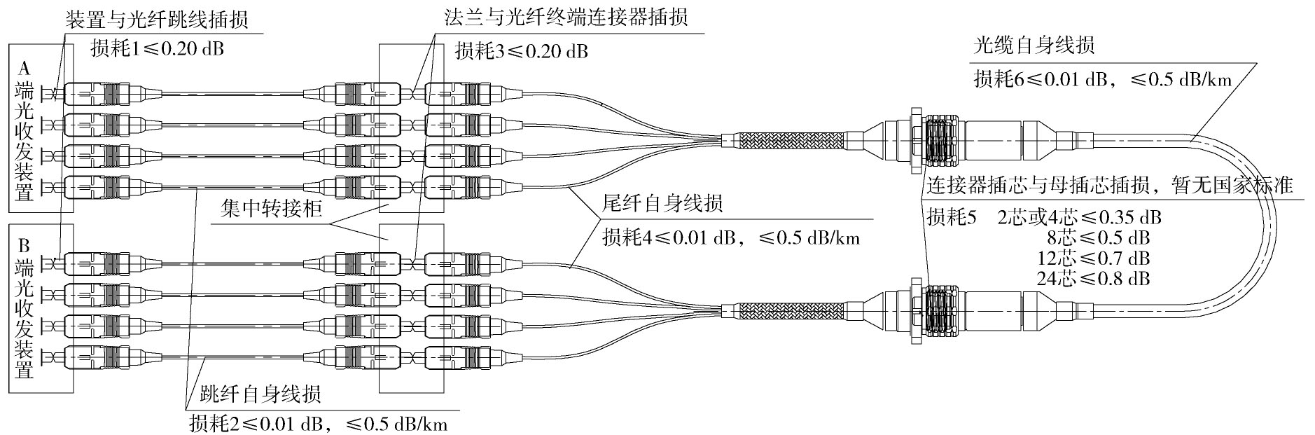
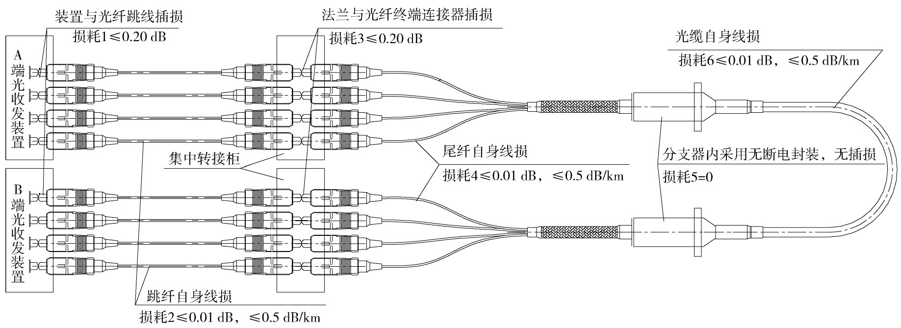
  • 预制光缆衰减与结构型式和连接方式有关。预制光缆按结构型式可分为分支式预制光缆及对插式连接器预制光缆,按连接方案可分为直接连接装置方案和通过柜内跳线转接连接装置方案。以工程常见的通过跳线转接的连接方式为例,预制光缆链路插接损耗值如图1图2所示。

    Figure 1.  The schematic diagram of the insertion loss of non-direct branching type prefabricated optical cable

    Figure 2.  The schematic diagram of the insertion loss of non-direct connection type prefabricated optical cable

    通过图1图2几种光缆的连接方式可知,光路除光缆自身光纤损耗外,需额外增加插接点、熔接点、转接点的损耗。具体插入损耗如表2表3所示。

    光缆形式 分支器型预制光缆 对插式连接器型预制光缆
    预制芯数/芯 12 12
    断点数量/个 4 6
    插入损耗/dB 0.2+0.2+0.2+0.2=0.8 0.2+0.2+0.7+0.7+0.2+0.2=2.2

    Table 2.  Prefabricated optical cable insertion loss comparison table

    项目 参数  
    光纤类型 A1b(62.5/125 μm)多模 B1.3(9/125 μm)单模
    光纤衰减系数 ≤3.5 dB/km@850 nm ≤0.5 dB/km@1 310 nm
    ≤1.5 dB/km@1 300 nm ≤0.4 dB/km@1 550 nm
    带宽 ≥200 MHz·km@850 nm
    ≥500 MHz·km@1 300 nm

    Table 3.  Optical cable attenuation coefficient table

    通过以上对比可知:

    1)预制光缆采用两头终端连接器与装置设备直连方案时,分支式预制光缆损耗只与光纤本身固有损耗有关,对插式连接器预制光缆损耗除光纤本身固有损耗外,还与连接器的插接损耗有关。

    2)直连装置方案比转接方案损耗要低,每转接一次,链路损耗增加0.2 dB。

    3)对插式连接器型预制光缆比分支器型预制光缆损耗要大,且芯数越多,损耗越大。

    结合上述预制光缆衰减控制对比结果,给出预制光缆工程应用方案如下:

    1)对于要求集中转接的预制光缆连接,建议采用对插式连接器型预制光缆,否则可采用分支器型预制光缆。

    2)对于直接连接或者柜内跳线转接次数较少的预制光缆连接,建议采用对插式连接器型预制光缆,对于转接次数较多或者对衰减要求较高的预制光缆连接,建议采用分支器型预制光缆。

    3)对于芯数不大于12芯的预制光缆连接,建议采用对插式连接器型预制光缆,对于芯数大于12芯的预制光缆连接,建议采用分支器型预制光缆。

  • 预制光缆敷设时应预留适当的余量,且需精确控制预留长度。若预留长度不够,则需退回厂家重新加工及发货,对工程工期造成延误;若预留长度过长,给柜内盘线困难,且影响舱内光缆敷设、整齐、美观。因此,如何有效控制预制光缆余长在工程实施时非常重要。

    预制光缆余长控制问题主要体现在室外至室内或预制舱之间的预制光缆长度控制,解决方案如下:首先,确定预制光缆长度计算原则,精准控制预制光缆长度;其次,通过预制光缆余长分散至各自屏柜或设置迂回井放置,实现预制光缆余长收纳。

    预制光缆余长主要来自于双端预制光缆,对于单端预制光缆,冗余较长光缆可进行现场裁剪,无需考虑收纳空间。预制光缆可分为分散配线方式和预制舱内集中配线方式。

    预制光缆采用分散配线方式时,由于预制光缆分散至各个屏柜,单个屏柜的预制光缆根数不多,可选择预制舱内屏柜或户外机柜其中一端进行盘整,直接将光缆余长就近于屏柜盘起,扎紧,就近放置于屏柜周边光缆槽盒内或屏柜底下方,也可通过柜内固定板高低根据现场实际情况进行适当调整,满足光缆余长的要求。

    预制光缆采用预制舱内集中配线方式时,由于集中转屏柜的预制光缆根数较多,若直接将光缆余长收纳在屏柜周边光缆槽盒内或集中转屏柜下方,对空间要求较大,且日后检修、维护困难。针对该问题的余长收纳方案有两种:

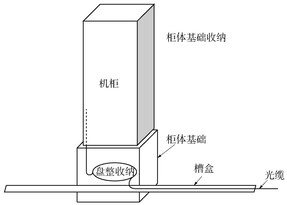
    方案一:对于预制光缆通过预制舱内集中转屏柜至户外控制柜的情况,可在户外机柜基础内部设置收纳空间对预制光缆余长进行盘整收纳,收纳方案如图3所示。但该方案仅适用于一侧为户外控制柜的预制光缆敷设,不适用于室与室或舱与舱之间的预制光缆余长的收纳。

    Figure 3.  The schematic diagram of outdoor control cabinet optical fiber cable residual length acceptance

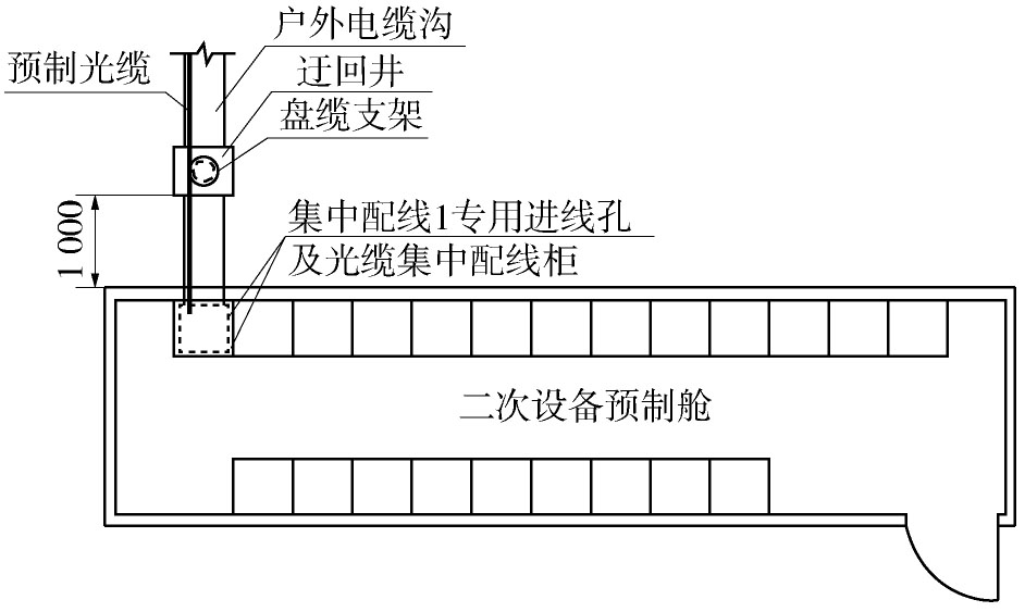
    方案二:在预制舱外电缆沟入口距离端部约1米处设置方形的迂回井,并在迂回井中间设置盘缆支架,用于收纳预制光缆余长。站内电缆沟贯穿预制舱底部,且舱两端的底部各设1个500×500 mm的进线孔,便于舱内外光缆接线。施工图设计时通过光、电缆敷设分层布置图明确线缆敷设顺序及位置,减少光缆冗余长度,实现整体光、电缆布置。采用预制舱外电缆沟设置方形的迂回井方案时,可有效控制光缆的余长,且便于日后预制光缆调整、检修、维护。本方案适用于各种配线方式时的预制光缆余长收纳,并可与方案一结合使用。具体方案如图4图5所示。

    Figure 4.  The layout schematic diagram of cable ditch detours well

    Figure 5.  The section schematic diagram of cable ditch detours well

  • 标准配送式变电站采用模块化、标准化、工厂化生产,是未来变电站发展的新方向。随着标准配送式变电站建设模式在电网工程应用的不断推广,国内对变电站模块化建设技术的研究和应用日益增加。预制光缆作为实现二次设备间模块化、标准化连接的重要手段,有效提高了标准配送式变电站现场光缆接线的质量与效率,在标准配送式变电站内得以广泛应用,但同时存在工程应用方案众多、工程实施问题较多等情况。本论文结合标准配送式变电站预制光缆的工程应用方案现状及需求,结合预制光缆的结构型式、连接光缆、预制方式等因素对预制光缆的工程应用方案进行研究并给出标准化应用方案,同时对工程实施中的常见问题进行分析研究并提出解决方案,有助于实现预制光缆的标准化应用与工程推广。后期工程应用时,可结合本文的研究成果,根据标准配送式变电站的工程规模与设备布置选择适用的工程应用方案和工程实施方案,实现全站光缆的现场模块化安装与接线。

Reference (10)

Catalog

    /

    DownLoad:  Full-Size Img  PowerPoint
    Return
    Return