• Peer Review
  • Non-profit
  • Global Open Access
  • Green Channel for Rising Stars
Volume 6 Issue 1
Jul.  2020
Turn off MathJax
Article Contents

Zhiping LI. Change Analysis of Inverter′s Electrical Values During HVDC Blocking[J]. SOUTHERN ENERGY CONSTRUCTION, 2019, 6(1): 98-103. doi: 10.16516/j.gedi.issn2095-8676.2019.01.017
Citation: Zhiping LI. Change Analysis of Inverter′s Electrical Values During HVDC Blocking[J]. SOUTHERN ENERGY CONSTRUCTION, 2019, 6(1): 98-103. doi: 10.16516/j.gedi.issn2095-8676.2019.01.017

Change Analysis of Inverter′s Electrical Values During HVDC Blocking

doi: 10.16516/j.gedi.issn2095-8676.2019.01.017
  • Received Date: 2018-07-13
  • Rev Recd Date: 2018-11-07
  • Publish Date: 2020-07-11
  •   [Introduction]  The system commission of HVDC is used to verify the overall performance of the project. It is necessary to analyze the recorded data of the electric values collected during commissioning in order to obtain the conclusion.  [Method]  Some recorded figure were not easy to understand. The converter circuit needed to be analyzed to understand the mechanism. This type of analysis method was demonstrated by analyzing typical electric quantity recorded figure.The voltage and current values change greatly when the recorded wave was triggered, which was related to the complex change of the trigger angle caused by the control. During this period, the single valve intermittent conduction, the two valve intermittent conduction, and the valve commutation conduction generated continuous current.Using circuit theory and power electronics technology to analyze the state of the inverter, it was found that inverter was an AC-DC hybrid circuit during the single-valve intermittent conduction, regardless of leakage current of the shut-off valve, the DC voltage was constant.  [Result]  Based on the theoretical results, analyze the inverter side electric quantity recording wave when a low-voltage valve group of a UHV project is blocked, can be concluded that if the applied DC voltage is greater than the average DC voltage of the inverter, under the supplemental pulse mechanism a continuous current occur.  [Conclusion]  The process of voltage and current in the recording wave is well explained, and the necessity and correctness of the control behavior are verified. It can be used as reference for HVDC project commission analysis and provide support for commission conclusions.
  • [1] 浙江大学直流输电编写组. 直流输电 [M]. 北京:中国电力出版社,1982.

    Zhejiang University DC Transmission Writing Group. Direct current transmission [M]. Beijing:China Electric Power Press,1982.
    [2] 赵畹君. 高压直流输电工程技术 [M]. 北京:中国电力出版社,2004.

    ZHAO W J. High-voltage direct current transmission engineering technology [M]. Beijing:China Electric Power Press,2004.
    [3] 中华人民共和国国家质量监督检验检疫总局,中国国家标准化管理委员会. 高压直流输电晶闸管阀设计导则:GB/Z 30424—2013 [S]. 北京:中国计划出报社,2013.

    General Administration of Quality Supervision, Inspection and Quarantine of the People′s Republic of China, China National Standardization Administration Committee. Design guidelines for high-voltage DC transmission thyristor valves: GB/Z 30424—2013 [S]. Beijing:China Planning Press,2013.
    [4] 汤广福. 电力系统电力电子及其试验技术 [M]. 北京:中国电力出版社,2015.

    TANG G F.Power system power electronics and its test technology [M]. Beijing:China Electric Power Press,2015.
    [5] 刘杰,张静,曹均正,等. 直流输电换流阀阻尼系统特性研究 [J]. 中国电机工程学报,2012,32(30): 16-22+5.

    LIU J, ZHANG J, CAO J Z, et al. Research on characteristics of damping system of DC transmission converter valve [J]. Proceeding of the CESS,2012,32(30): 16-22+5.
    [6] 岳珂,孙玮,刘隆晨,等. 载流子寿命与高压晶闸管反向恢复特性的关系 [J]. 高电压技术,2017,43(12): 3944-3949.

    QIU K, SUN W, LIU L C,et al. Correlation between carrier lifetime and reverse recovery characteristics of high power thyristors [J]. High Voltage Engineering,2017,43(12): 3944-3949.
    [7] 郭焕,汤广福,于海玉,等. 高压直流输电晶闸管阀开通的电流应力分析 [J]. 中国电机工程学报,2011,31(15): 1-7.

    GUO H, TANG G F, YU H Y,et al. Analysis of turn-on current stress on HVDC thyristor valve [J]. Proceeding of the CESS,2011,31(15): 1-7.
    [8] 郭焕,温家良,汤广福,等. 高压直流输电晶闸管阀关断的电压应力分析 [J]. 中国电机工程学报,2010,30(12): 1-6.

    GUO H, WEN J L, TANG G F,et al. Analysis of turn-off voltage stress on HVDC thyristo valve [J]. Proceeding of the CESS,2010,30(12): 1-6.
    [9] 汤广福,贺之渊,邓占锋. 基于器件物理特性的晶闸管阀串联机制系统化研究 [J]. 中国电机工程学报,2006,26(12): 39-44.

    TANG G F, HE Z Y, DENG Z F. Systematic study on valves series mechanism based on devices physical properties [J]. Proceeding of the CESS,2006,26(12): 39-44.
    [10] 姚斌,施世鸿,陈荔. ±1 100 kV特高压直流换流站直流场导体的电磁计算与设计选型 [J]. 南方能源建设,2016,3(4): 37-41.

    YAO B, SHI S H, CHEN L. Electromagnetic environment calculation and design of ±1 100 kV DC conductor in UHVDC converter station [J]. Southern Energy Construction,2016,3(4): 37-41.
    [11] 李志平. 高压直流输电系统解锁过程的原理分析 [J]. 南方电网技术,2016,10(4): 284.

    LI Z P. Principle analysis of deblocking process of HVDC transmission system [J]. Southern Power System Technology [J]. 2016,10(4): 284.
    [12] 李志平.高压直流开路电压建立过程分析 [J]. 南方电网技术,2014,8(3): 37-41.

    LI Z P. Analysis of the establishment process of high voltage DC open circuit voltage [J]. Southern Power System Technology [J]. 2014,8(3): 37-41.
    [13] 李泰,荆雪记,孔令凯,等. 高压直流输电系统开路试验原理分析与工程建议 [J]. 电力系统保护与控制,2015,43(11): 134-141.

    LI T, JING X J, KONG L K,et al. Principle analysis and engineering suggestions for open circuit test of HVDC transmission system [J]. Power System Protection and Control,2015,43(11): 134-141.
    [14] 李侠,陈干. 高压直流输电开路试验中换流阀设备保护的探讨 [J]. 高压电器,2012,48(3): 86-89.

    LI X, CHEN G. Discussion on protection of converter valve equipment in open circuit test of HVDC transmission [J]. High Voltage Apparatus,2012,48(3): 86-89.
    [15] 李少华,刘涛,苏匀,等. ±800 kV特高压直流输电系统解锁/闭锁研究 [J]. 电力系统保护与控制,2010,38(6): 84-87.

    LI S H, LIU T, SU Y,et al. Research on de-bocking/blocking operation in ±800 kV UHVDC transmission system [J]. Power System Protection and Control,2010,38(6): 84-87.
    [16] 霍鹏飞,王国功,刘敏,等. 向上±800 kV特高压直流输电工程的直流保护闭锁策励略 [J]. 电力系统保护与控制,2011,39(9): 137-139+144.

    HUO P F, WANG G G, LIU M,et al. DC protection lock strategy for Xiangjiaba-Shanghai ±800 kV UHV DC transmission project [J]. Power System Protection and Control,2011,39(9): 137-139+144.
  • 通讯作者: 陈斌, bchen63@163.com
    • 1. 

      沈阳化工大学材料科学与工程学院 沈阳 110142

    1. 本站搜索
    2. 百度学术搜索
    3. 万方数据库搜索
    4. CNKI搜索

Figures(5)  / Tables(2)

Article Metrics

Article views(239) PDF downloads(23) Cited by()

Related

Change Analysis of Inverter′s Electrical Values During HVDC Blocking

doi: 10.16516/j.gedi.issn2095-8676.2019.01.017

Abstract:   [Introduction]  The system commission of HVDC is used to verify the overall performance of the project. It is necessary to analyze the recorded data of the electric values collected during commissioning in order to obtain the conclusion.  [Method]  Some recorded figure were not easy to understand. The converter circuit needed to be analyzed to understand the mechanism. This type of analysis method was demonstrated by analyzing typical electric quantity recorded figure.The voltage and current values change greatly when the recorded wave was triggered, which was related to the complex change of the trigger angle caused by the control. During this period, the single valve intermittent conduction, the two valve intermittent conduction, and the valve commutation conduction generated continuous current.Using circuit theory and power electronics technology to analyze the state of the inverter, it was found that inverter was an AC-DC hybrid circuit during the single-valve intermittent conduction, regardless of leakage current of the shut-off valve, the DC voltage was constant.  [Result]  Based on the theoretical results, analyze the inverter side electric quantity recording wave when a low-voltage valve group of a UHV project is blocked, can be concluded that if the applied DC voltage is greater than the average DC voltage of the inverter, under the supplemental pulse mechanism a continuous current occur.  [Conclusion]  The process of voltage and current in the recording wave is well explained, and the necessity and correctness of the control behavior are verified. It can be used as reference for HVDC project commission analysis and provide support for commission conclusions.

Zhiping LI. Change Analysis of Inverter′s Electrical Values During HVDC Blocking[J]. SOUTHERN ENERGY CONSTRUCTION, 2019, 6(1): 98-103. doi: 10.16516/j.gedi.issn2095-8676.2019.01.017
Citation: Zhiping LI. Change Analysis of Inverter′s Electrical Values During HVDC Blocking[J]. SOUTHERN ENERGY CONSTRUCTION, 2019, 6(1): 98-103. doi: 10.16516/j.gedi.issn2095-8676.2019.01.017
  • 高压直流输电工程的系统调试是工程建设的最后一个环节,用于验证工程项目的整体性能及接入电网系统的适应性。试验项目包含投运后可能会出现的运行接线方式,也人为的设置一些故障的试验项目,目的都是先行检验。调试的成果之一是收集电气量录波,通过对其分析得出试验结论。

    触发录波时通常高压直流的电压电流值急剧变化,和控制导致的触发角复杂变化相关联,期间出现换流器单阀间歇导通、两阀间歇导通、阀换相导通产生连续电流的情况。文献[1,2,3]是基于连续电流工况的原理分析。文献[4,5,6,7,8,9,10]主要对阀及组件的暂态过程进行分析,未对阀通断转换的条件进行分析。国内对于前两种情况所做的理论分析工作呈现空白状态。需要运用电路理论和电力电子技术对换流器的电路进行分析。本文以某一特高压工程单个低端阀组闭锁时的逆变侧电气量录波图为例,首先对此过程中形成的特殊电路进行理论上的分析,利用分析的结论来解释录波图的电气量变化的机理。

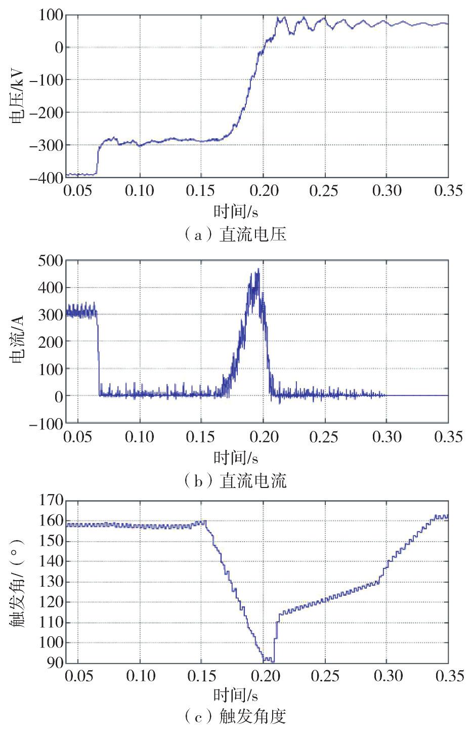
  • 逆变侧闭锁时的电气量录波图如图1所示,其过程可分为五个阶段。第一阶段,电流由运行值降为零,电压由-400 kV变为-290 kV,触发角157°不变,过程时间几个毫秒;第二阶段,有间歇性小电流,电压保持-290 kV,触发角157°不变,延续时间100 ms;第三阶段,电流由零上升到将近500 A再降为零,电压由-290 kV变为零又升到反向的几十千伏,触发角复杂变化,先稳定后移相减少到90°;第四阶段有间歇性小电流,电压从几十千伏到接近一百千伏波动,触发角由90°又移相增加164°,延续时间近100 ms。第五阶段电流为零,电压稳定在几十千伏,触发角164°,延续时间很长。

    Figure 1.  Recording of electric quantity when the inverter is deblocked

    为了解释上述现象,需对换流器电路进行研究,特别是换流器单阀间歇导通的工作状态,并结合阀组补脉冲功能,以揭示其中机理。上述的过程出现了逆变侧十二脉动桥外加电容性质直流电压的电路,触发角先稳定后移相减少到90°又移相增加,以此为例进行理论分析。

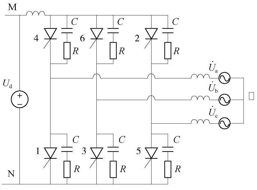
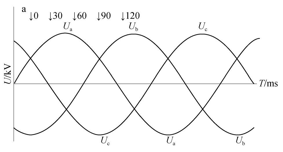
  • 以逆变侧六脉动桥外加直流电压为例进行分析[11,12,13,14,15,16],所加电压极性和运行时相同,即换流器共阳极为正共阴极为负,如图2所示。交流电压波形如图3所示。

    Figure 2.  Inverter side six-pulse bridge connect DC voltage

    Figure 3.  AC voltage waveform

    假设三相交流电源平衡,其中性点为零电位参考,外加直流电压为Ud。用电路理论的叠加原理分析可得,在阀被触发前,桥阀共阴极电位为:

    ((1))

    共阳极电位为:

    ((2))

    如果触发角为α,设定A相阀1为第一个触发阀,触发时其阳极电位即为A相电源电压:

    ((3))

    式中:Eφ为电源相电压有效值。

    阀1阴极电位为-0.5Ud,这时阀1导通的条件为阳极电位大于阴极电位,否则阀不导通。

    如果触发角α小于160°,外加一定的直流电压,比如Ud=(0.5~1)Eφ,使阀1出现正向偏置,这时阀1会导通。产生电流路径为:换流变A相电源经阀1至外加直流电源至阀2、4、6的RC回路,再经换流变A、B、C相电源回到中性点。这个过渡过程待RC回路的电容充电完成后结束,同时阀1截止,时间大约为RC回路时间常数的3倍,3τ=3RC=150 μS,相当于2.7°电角度。这时N,M点电位:

    ((4))

    式中:δ0=2.7°。

    ((5))

    不考虑RC回路的电容上的电荷经截止的阀放电,则N,M点电位将保持到阀2触发之前时刻。

    类似分析,经过60°电角度相应的时间,阀2触发导通,随后截止,这时M,N点电位改变:

    ((6))
    ((7))

    N点电位改变可能会使阀1产生补脉冲导通。阀基电子设备对于电流不连续工况设计了补脉冲功能,在控制脉冲信号的有效窗口时间内,通常相当于120°电角度的时间,阀截止后又检测到有正向偏置电压,则按一定规则再发点火脉冲。

    阀1产生补脉冲导通的条件是有正向偏置电压,即:

    ((8))

    或:

    ((9))

    阀2触发瞬间:

    ((10))

    如果阀2触发导通尚未截止阀1即产生补脉冲导通,那么就出现两阀导通的工况。

    如果两阀导通的工况能延续到阀3触发和阀1换相,则出现连续电流。需要的条件是外加直流电压大于逆变侧换流器的直流平均电压,不考虑换相损失的值为:

    ((11))

    现有的教材专著有详述。

    可以运用上面的结论分析一种特殊的情况,即出口端短路。相应Ud=0,如果触发角α<120°则Uca<0,满足Ud>Uca,那么就出现两阀导通的工况。如果触发角α小于90°则UI<0,满足Ud>UI,则出现连续电流。

    对于十二脉动换流器这方面过程和六脉动换流器有较大的差异,同样可用电路理论的叠加原理分析,所得结论类似。

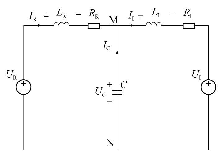
  • 第一阶段由整流侧移相引起,可用一个简化的电路分析,如图4所示。电路中间的电容为整流逆变站间电容的综合,包含直流滤波器电容和线路电容,以这个电容为界将直流系统分为整流和逆变两部分。正常运行时整流和逆变的电流相等,三个电压值接近。闭锁后整流侧移相,UR变小后变负,LR两端电压变负,数值可达直流电压的两倍,而LI两端电压变负,数值为电容电压的变化值。可知整流电流急剧减少而逆变电流缓慢减少,差值部分由电容放电补充。整流电流先到零其阀先截止,逆变电流后到零阀后截止,电容停止放电,电压保持,这是录波第一阶段电压由-400 kV变为-290 kV的原因。

    Figure 4.  Simplified circuit of HVDC system

    第二阶段可应用上节的结论进行分析。此时系统电压为532 kV,换流变抽头为5,每个档位变比1.25%,额定变比525/161.2 kV,可以计算出换流变的阀侧空载电压154 kV。由直流电压-290 kV除以2得到六脉动桥出口对应的直流电压为145 kV。

    按照上节推导,触发角157°,阀2触发时:

    ((12))
    ((13))

    Ud=145 kV>Uca=131 kV出现两阀导通的工况。逆变侧换流器的直流平均电压:

    ((14))
    ((15))

    大于六脉动桥出口所加的直流电压,不出现连续电流,只是出现两阀间歇导通的工况。相应波形图上呈现间歇性电流而外加电压不变。

    第三阶段电流由零上升到将近500 A再降为零,电压由-290 kV变为0 kV又升到反向几十千伏,触发角开始移相减少到90°又移相增加到164°。

    由录波图选取需要的电气量填入表1,又按公式(16)计算触发角α下的逆变直流平均电压:

    时间点/s 六脉动Ud/kV 直流电流Id/A 触发角α/(°) 六脉动UI计算值/kV 备注
    0.155 142.0 20.4 154.0 188.40 没有连续电流
    0.167 140.0 67.0 138.3 155.20 没有连续电流
    0.175 127.8 73.7 125.2 119.80 有连续电流
    0.180 114.0 146.8 120.7 107.80 有连续电流
    0.185 91.0 241.3 113.3 83.75 有连续电流
    0.190 49.8 442.3 106.0 59.60 有连续电流
    0.193 37.8 429.9 103.0 49.10 有连续电流
    0.196 9.0 462.3 97.3 29.60 有连续电流
    0.200 -2.2 330.0 91.0 1.64 有连续电流
    0.207 -13.0 77.0 90.4 0.00 有连续电流
    0.208 -19.0 3.4 90.5 0.00 没有连续电流

    Table 1.  Electrical quantity when the inverter side is locked Tab.1

    ((16))

    填入表1,阀侧空载交流线电压为:

    ((17))

    根据换流变的参数算出:

    ((18))

    移相开始时触发角α减少,UI减少而Ud不变。当Ud>UI时出现连续电流,外加电压Ud因电容放电而下降,随着触发角α减少UI也减少,但在电流上升过程中保持Ud>UI,是因为回路中有平波电抗和换流变短路电抗,电流的增量取决于Ud-UI的值,如表1的3~5行所示。随着电流增大Ud下降加快,这时UI随着触发角α减少也下降加快,如表1的6~8行所示,电流值很大而变化不大。因为控制移相触发角α到90°就不再减少,使这个进程发生转折,这时,UI=0电压Ud因电容放电而下降,随时间延续Ud-UI变负而且数值加大,电流下降速度加快,直至电流为零后换流器截止。由波形图及表1可见,触发角α到91°电流急剧下降。

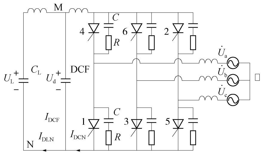
    换流器截止后进入闭锁过程的第四阶段,如图5所示,类似开路试验的工况。如果触发角α保持90°则会产生很高的开路电压,为避免这样需要移相增加触发角α。这阶段有间歇性小电流,电压从几十千伏到一百千伏波动,触发角上升,延续时间100 ms以上。

    Figure 5.  Fourth stage circuit

    计算:

    ((19))
    ((20))

    计算值如表2所示。

    时间点/s 六脉动Ud/kV 直流电流IdCN/A 直流电流IdLN/A 触发角α/(°) Uca计算值/kV Ua计算值/kV 备注
    0.209 -17.0 6.240 -23.80 102.10 -66.90 93.30 间歇性
    两阀导通
    0.210 -29.0 -5.000 -45.10 102.10 -66.90 93.30 间歇性
    两阀导通
    0.213 -39.2 46.800 40.80 114.10 -22.70 73.70 单阀导通
    0.217 -46.2 1.600 20.80 115.60 -16.70 71.00 单阀导通
    0.220 -28.6 27.300 46.90 116.30 -14.00 69.76 单阀导通
    0.225 —20.7 -6.640 -9.16 115.60 -16.70 71.00 单阀导通
    0.230 -38.5 17.300 -5.90 118.20 -6.84 66.25 单阀导通
    0.233 -45.1 -2.800 -10.10 118.50 -5.69 65.70 单阀导通
    0.240 -25.0 1.550 0.58 120.15 0.00 62.87 单阀导通
    0.300 -37.1 -0.001 -3.98 137.10 - 28.07 单阀导通
    0.310 -37.1 0.000 -3.40 144.10 - 12.90 没阀导通

    Table 2.  Electrical quantity when the inverter side is locked Tab.2

    根据Ud>Uca判断是否有间歇性两阀导通,根据 判断是否有间歇性单阀导通。间歇性两阀导通时直流电压反极性快速上升,即幅值上升,单阀间歇性导通直流电压也反极性上升。而第五、六第九测点时刻直流电压反极性下降,即幅值下降,分析是因为直流线路电流震荡导致直流滤波器充放电而产生。按照正常运行的电流方向有IDfIdLN-IdCN为直流滤波器充电电流,其值为正则直流电压上升,反极性直流电压幅值相应减少;为负则直流电压下降,反极性直流电压幅值相应上升。

  • 对逆变侧阀组闭锁时的电气量变化分析后得到结论如下:第一阶段,电流由运行值降为零,电压幅值也下降,是两换流站间的直流滤波器电容及线路电容经逆变侧放电至阀截止时刻,剩余电荷呈现的电压。第二阶段,阀间歇性导通产生小电流,剩余电荷维持稳定的电压。第三阶段,从大触发角开始移相减少过程中,换流器的直流平均电压减少到小于外加电压时,出现阀导通的连续电流使电容放电,外加电压下降,电流的增量正比于两个直流电压之差,各量相互影响使电流由零上升到将近500 A再降为零,电压变为零又升到反向的几十千伏。第四阶段,类似开路电压试验工况,阀间歇性导通产生小电流,叠加线路震荡电流使电压从几十千伏到接近一百千伏波动,为避免出现过大的开路电压,触发角由90°又移相增加到164°。最后电流为零,电压稳定在几十千伏,阀有触发没有开通。

    由此很好地解释了电压电流量变化过程,验证了控制行为的必要性和正确性。可为直流工程调试录波分析做参考,为调试下结论提供支持。

Reference (16)

Catalog

    /

    DownLoad:  Full-Size Img  PowerPoint
    Return
    Return