• Peer Review
  • Non-profit
  • Global Open Access
  • Green Channel for Rising Stars
Volume 6 Issue 4
Jul.  2020
Turn off MathJax
Article Contents

LI Qiang, CAI Rujin, LIU Yu. Research and Application of By-pass Control System for 700 MW Unit[J]. SOUTHERN ENERGY CONSTRUCTION, 2019, 6(4): 54-58. doi: 10.16516/j.gedi.issn2095-8676.2019.04.008
Citation: LI Qiang, CAI Rujin, LIU Yu. Research and Application of By-pass Control System for 700 MW Unit[J]. SOUTHERN ENERGY CONSTRUCTION, 2019, 6(4): 54-58. doi: 10.16516/j.gedi.issn2095-8676.2019.04.008

Research and Application of By-pass Control System for 700 MW Unit

doi: 10.16516/j.gedi.issn2095-8676.2019.04.008
  • Received Date: 2019-07-19
  • Rev Recd Date: 2019-08-06
  • Publish Date: 2020-07-11
  •   [Introduction]  The by-pass system of Zhuhai Power Station is designed by BTG company whose upgrade plan has been the prime focus of our group, since its function control by electric element using analog signal which leads to low reliability and regulation performance.  [Method]  In this investigation we measured the localize redundancy control method which was using a innovative structure mixed with XDC800B and ATOS, including the Xinhua DCS/DEH control system XDC800, the high and low pressure turbine by-pass valves and their spray control valves are controlled by xSV valve control card of XDC800 system and ATOS digital power amplifier card.In order to further improve the stability of by-pass control system, the undisturbed automatic switching function of high and low pressure by-pass valves and their spray control valves is realized by using self-developed redundant switching control board.  [Result]  The results shows that the function of new system is completely identical with the original imported equipment which also achieving higher data control precision and make the unit runs more stable, while the requirements of unit start and shutdown, pressure control and FCB function under complex operating conditions are fully meet.  [Conclusion]  Thus, we demonstrate the feasibility of the localize redundancy control method, and this this is a successful project suits to Zhuhai Power Station with small construction area, short period and high economic benefit; This work provides some guidance for further study on by-pass system upgrade in the field of power generation.
  • [1] 赖加良. 珠海发电厂2×700 MW机组旁路系统介绍 [J]. 湖南电力,2002(5):54-56.

    LAI J L. Zhuahai power station 2×700 MW unit by-pass system introduction [J]. Hunan Power,2002(5):54-56.
    [2] 吴家凯,黄涛. FCB功能火电机组辅机选型技术研究 [J]. 南方能源建设,2018,5(1):59-62.

    WU J K,HUANG T. The Research on selection technology of auxiliary equipment for thermal power station with FCB function [J]. South China Energy Construction,2018,5(1):59-62.
    [3] 屈晓强. 600 MW火电机组汽轮机旁路系统存在问题分析 [J]. 中国高新区,2017(24):134-135.

    QU X Q.The analysis of problems in steam turbine by-pass system of 600 MW thermal power unit [J]. China High-tech Zone,2017(24):134-135.
    [4] 柳明,任杰. 火力发电厂汽轮发电机旁路及运行方式探究 [J]. 现代工业经济和信息化,2017,7(17):61-62+67.

    LIU M,REN J. The Research on steam turbine by-pass system of thermal power unit and its operation mode [J]. Modern Industrial Economy and Informatization,2017,7(17):61-62+67.
    [5] 周磊,党少佳,郭瑞君,等. 汽轮机旁路温度控制系统的优化 [J].内蒙古电力技术,2019,37(1):46-51.

    ZHOU L,DANG S J,GUO R J,et al,The Optimization of temperature control for steam turbine by-pass system [J]. The Inner Mongolia Power,2019,37(1):46-51.
  • 通讯作者: 陈斌, bchen63@163.com
    • 1. 

      沈阳化工大学材料科学与工程学院 沈阳 110142

    1. 本站搜索
    2. 百度学术搜索
    3. 万方数据库搜索
    4. CNKI搜索

Figures(5)  / Tables(4)

Article Metrics

Article views(200) PDF downloads(19) Cited by()

Related

Research and Application of By-pass Control System for 700 MW Unit

doi: 10.16516/j.gedi.issn2095-8676.2019.04.008

Abstract:   [Introduction]  The by-pass system of Zhuhai Power Station is designed by BTG company whose upgrade plan has been the prime focus of our group, since its function control by electric element using analog signal which leads to low reliability and regulation performance.  [Method]  In this investigation we measured the localize redundancy control method which was using a innovative structure mixed with XDC800B and ATOS, including the Xinhua DCS/DEH control system XDC800, the high and low pressure turbine by-pass valves and their spray control valves are controlled by xSV valve control card of XDC800 system and ATOS digital power amplifier card.In order to further improve the stability of by-pass control system, the undisturbed automatic switching function of high and low pressure by-pass valves and their spray control valves is realized by using self-developed redundant switching control board.  [Result]  The results shows that the function of new system is completely identical with the original imported equipment which also achieving higher data control precision and make the unit runs more stable, while the requirements of unit start and shutdown, pressure control and FCB function under complex operating conditions are fully meet.  [Conclusion]  Thus, we demonstrate the feasibility of the localize redundancy control method, and this this is a successful project suits to Zhuhai Power Station with small construction area, short period and high economic benefit; This work provides some guidance for further study on by-pass system upgrade in the field of power generation.

LI Qiang, CAI Rujin, LIU Yu. Research and Application of By-pass Control System for 700 MW Unit[J]. SOUTHERN ENERGY CONSTRUCTION, 2019, 6(4): 54-58. doi: 10.16516/j.gedi.issn2095-8676.2019.04.008
Citation: LI Qiang, CAI Rujin, LIU Yu. Research and Application of By-pass Control System for 700 MW Unit[J]. SOUTHERN ENERGY CONSTRUCTION, 2019, 6(4): 54-58. doi: 10.16516/j.gedi.issn2095-8676.2019.04.008
  • 珠海发电厂一期工程2×700 MW机组设有由瑞典BTG公司生产的高、低压2级串联旁路系统,容量为40%BMCR。高压旁路只有1路,低压旁路采用2路并列运行。高压旁路为过热器出口蒸汽经减温减压后到再热器进口;低压旁路为再热器出口蒸汽经减温减压后去凝汽器。高旁和低旁都是由控制油站、储能系统、旁路控制系统、ATOS比例阀和快开快关阀等组成。其中高压旁路包括1个压力调节阀,1个减温水调节阀和1个减温水截止阀。每一路低压旁路包括1个压力调节阀和1个减温水调节阀,2路低旁共用1套控制油站[1]

    旁路控制系统是该厂的自动电厂控制系统(APC)的一个子系统,它由BTG公司自行设计的伺服放大驱动卡件PCS系统构成。PCS系统为阀门定位系统,主要功能是通过比较APC系统的阀门指令和LVDT反馈信号,将信号差值通过伺服放大转换为比例阀所需要的电流[2],通过比例积分的算法对阀位进行精准控制,同时配合底板上的继电器回路,进行旁路阀的快关、快开保护。

  • 目前使用的PCS系统是由BTG公司自主设计,还属于模拟量电路,其控制卡件与模拟量功放卡均集中在同一块底板上。此系统的所有功能均由模拟量的电气元件实现,所以可靠性、易调节性和直观程度都较低,现场进行调整时,要使用两4~20 mA信号发生器模拟指令和反馈,用万用表测量偏差和输出信号,反复进行调校,才能够达到控制要求,调整结果完全由操作人员的经验决定,无法进行有效检测,不利于现场维护[3]。BTG公司被CCI公司收购后,PCS系统的关键部件阀门控制伺服卡已停产,备件及服务已不能满足电厂机组正常运行的需求。

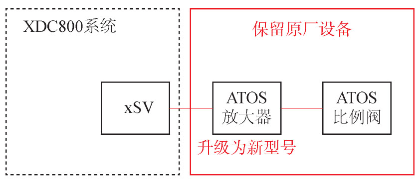
  • 1)根据设备维护经验,就地ATOS比例阀、ATOS快开快关阀等旁路机柜之外的原有设备属于通用设备,相比专用设备具有故障率低、价格便宜等优势,应维持该部分设备不变,仅对现场控制系统实施整体更换。新控制系统将采用冗余控制,进一步提高旁路控制系统的安全性及稳定性。

    根据原机柜涵盖的功能范围和内容,实现系统整体替换,实现并保留原有油站的硬按钮启停操作和状态指示灯监视模式。

    2)旁路控制系统机柜输入电源配置应维持两路电源供电(一路为220 VAC、一路为110 VDC),各类电源及高选模块全部采用导轨式安装。

    3)控制系统部分使用阀门控制卡及ATOS的功放卡来控制旁路系统的比例阀。旁路比例阀控制配置为冗余控制方式,即两块阀门控制卡的输出信号,经伺服端子板分别输出到各自的功放端子板,两路功放端子板输出信号接入冗余切换板,一路功放卡输出,另一路功放卡热备用,发生故障时可以迅速完成冗余切换,提高控制的可靠性[4]

    4)快开快关功能设计应与原控制系统一致,确保快开/快关动作时,比例阀输出相应的全开/全关信号。

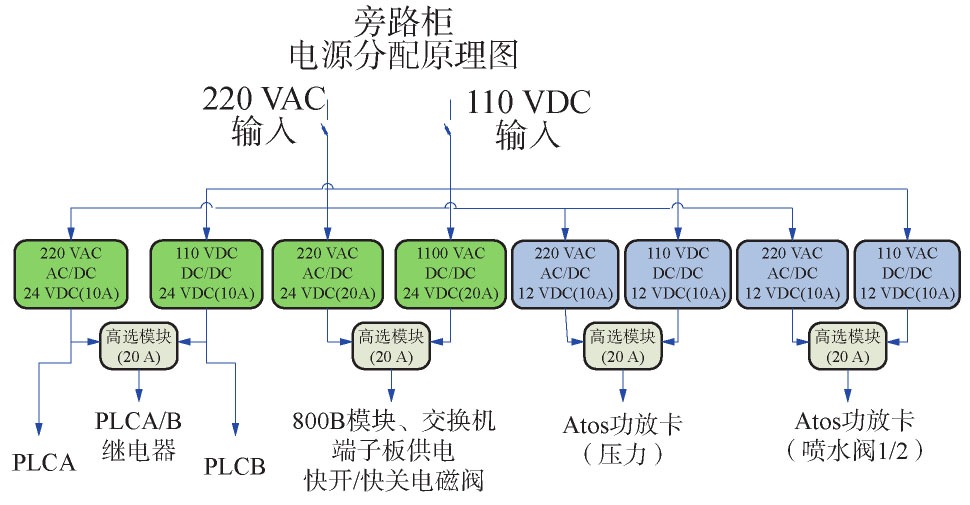
  • 根据原有系统特点,机柜输入电源一路为220 VAC、一路为110 VDC,分别经过AC/DC和DC/DC转换并经过高选后变为BTG伺服模件、快关阀的24 VDC电源。新系统将结合原有系统的特点和800B+ATOS混搭结构的新特点,采取如下电源配置方式,各类电源及高选模块全部采用导轨式安装。电源配置的基本原则为:800B电源与PLC电源完全独立、ATOS功放卡单独12 VDC电源供电、800B与快关电磁阀共用24 VDC电源。每类电源冗余配置,高选输出。新系统电源分配原理图如图1所示:

    Figure 1.  Power distribution diagram of new system

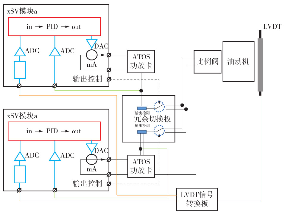
  • 控制系统部分使用新华DCS/DEH系统XDC800,使用系统集成的xSV阀门控制卡控制各个阀门,阀门线圈的驱动部分由新ATOS数字型功放卡进行控制。混搭控制原理图如图2所示。

    Figure 2.  Schematic diagram of mixed control

    新华冗余xSV阀门控制模块可实现1个伺服阀/比例阀的位置闭环控制,支持单/双路位置反馈信号冗余配置,具有快关/快开输出逻辑。xSV目前支持0~20 mA、±10 mA、±20 mA的驱动输出信号。新型ATOS数字放大器支持2.7 A电流驱动输出,可实现双向偏置、增益、斜波、震颤等设置,符合原有ATOS比例阀驱动要求。

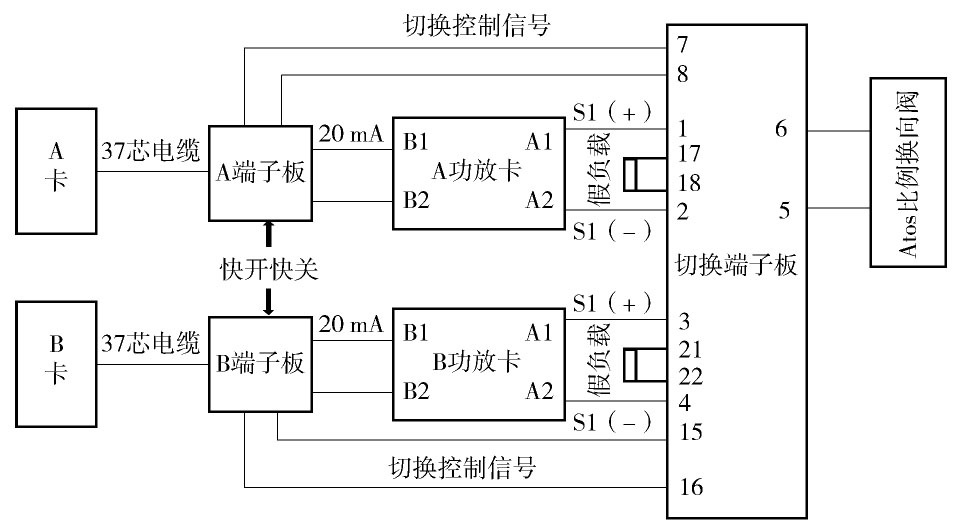
  • 冗余伺服阀控制模块通过切换端子板实现两套独立的伺服阀控制模块配合ATOS功放卡对同一个阀门进行位置闭环控制。互为冗余的伺服阀控制模块间通过冗余电缆实现状态的监控和数据交换。系统结构图如图3所示:

    Figure 3.  System structure diagram

    1)功能描述

    控制系统部分使用新华DCS/DEH系统XDC800,使用系统集成的xSV阀门控制卡控制各个阀门。两块xSV模块的输出信号,经伺服端子板分别输出到各自的ATOS功放端子板,两路ATOS功放端子板输出信号接入新研制的冗余切换板,切换后的大电流信号输出至比例阀,以开大或关小旁路阀门。冗余xSV模块设计为LVDT或mA作为阀门反馈信号,mA电流作为伺服阀控制输出。伺服阀控制信号并联输出,发生故障时可以迅速完成冗余切换,提高控制的可靠性[5]

    2)伺服控制部分的工作原理框图如图4所示。

    Figure 4.  Operating principle block diagram of servo control

    A卡(阀门卡)和A端子板(阀门端子板)以及A功放卡组成一组独立的控制环节;B卡(阀门卡)和B端子板(阀门端子板)以及B功放卡组成另一组冗余的控制环节;配合后端的切换端子板及比例阀,构成完整回路。

    当回路A通道输出控制处于允许模式时,回路B的输出控制就会处于开路模式,即任一时刻,只有一块xSV模块处于实际控制状态,另一块为热备份状态(采样阀门反馈信号并计算)。xSV模块输出通道带有输出电流检测和控制电路,实时监测输出电流的状态,并相应的联锁控制其输出。当模块a监测到故障时,就会释放输出控制权,此时模块b在检测到外部无输出后,会自动取得输出控制权(输出控制闭合),此时设备控制信号由回路A转移到回路B,实现前端两套控制环节的冗余切换。

    冗余通道的切换时间小于5 ms。一般伺服阀的快关时间在100 ms~300 ms之间,不考虑电液系统的延迟,理论上的最大扰动为5/100=5%。

    阀门卡通过阀门端子板接收快开快关信号、DCS开度指令信号、阀门反馈信号等,在内嵌的CPU中完成逻辑的PID计算,输出正负20 mA的控制电流,经过功放卡放大到正负2.7 A电流驱动比例阀。

    冗余阀门卡的切换逻辑包括:

    1)ADC硬件坏。

    2)DCS指令信号坏(超量程、断线)。

    3)阀门反馈信号坏(超量程、断线)。

    4)阀门端子板上第二路DI开路(端子3/19)。

    5)功放卡报警(端子7/23)。

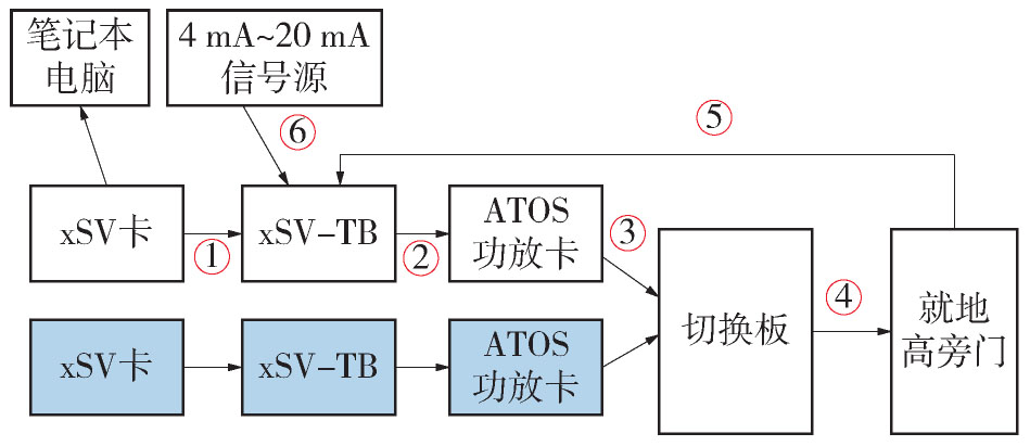
  • 为进一步验证新旁路控制系统的可行性及可靠性。需对由阀门卡(xSV)+端子板(xSV-TB)+ATOS功放卡+冗余切换板组成的旁路伺服控制部分进行测试,测试用旁路伺服控制部分系统框图如图5所示:

    Figure 5.  By-pass servo control system block diagram

    电缆和信号线连接说明表如表1所示:

    名称 描述或说明
    37芯预制电缆 实现阀门卡和端子板之间的互联
    正负20 mA指令信号 用于驱动ATOS功放卡的指令
    0~2.8 A/双电流 驱动电磁线圈电流,切换板的输入
    0~2.8 A/双电流 驱动电磁线圈电流,切换板的输出,到就地
    阀门反馈4~20 mA信号 就地实际开度反馈
    阀门指令4~20 mA信号 DCS系统阀门指令信号

    Table 1.  Instruction for connection of cables and signal lines

  • 根据原旁路控制系统阀门经验数据,预先设置功放卡的零位偏置电流为1.1 A,满位电流为2.8 A。阀门卡的放大倍数设置为6倍。通过DCS系统发送4 mA~20 mA全行程测试5个点,具体数据如表2所示:

    指令/(mA·V-1) 上行反馈 下行反馈 上下行偏差
    V % V %
    4/1 1.11 0 1.11 0 0
    8/2 2.01 23.5 2.01 23.5 0
    12/3 3.01 49.61 3.01 49.61 0
    16/4 3.99 75.2 4.01 75.72 0.52
    20/5 4.94 100 4.94 100 0

    Table 2.  Table of valve travel test

  • 通过DCS系统直接强制全开、全关信号,快开及快关信号,记录行程时间及输出电流如表3所示:

    测试项目 全行程时间在/s 快开/快关/s 输出电流/A
    指令4→20 mA 25 2 2.8
    指令20→4 mA 28 3 -2.8

    Table 3.  Table of switching time test

  • 为保证系统运行的可靠性及冗余切换功能的正确性,进行了相应的功能测试,具体测试内容如表4所示:

    测试项目 切换板输出 备注或措施
    断线位置① 故障卡切除 阀门保持
    断线位置② 未发生切换 阀门保持
    断线位置③ 0 阀门保持
    断线位置④ 0 阀门保持
    拔掉阀门卡 0 阀门保持
    停系统电源 0 阀门保持
    系统重新上电 功放卡上电瞬间有尖峰电流 阀门略有波动(5%范围内)

    Table 4.  Table of fault test

    通过以上测试可知,新华DCS/DEH系统XDC800与ATOS功放卡能够完美匹配,对比测试所得数据与原控制系统数据保持一致,且能够实现冗余自动无扰切换控制功能。

  • 本项目首创旁路控制系统的“XDC800B+ATOS混搭结构”,成功实现对旁路阀、快开、快关阀的控制及无扰自动切换功能。该系统的应用显著提升了旁路控制系统的安全性、稳定性及经济性。其关键技术及主要创新点在于:

    1)采用“XDC800B+ATOS混搭结构”,即上海新华DCS/DEH系统XDC800与电厂原有ATOS伺服卡进行匹配,实现对旁路阀门的控制。由于此结构在国内尚无应用先例,需对两个分属不同厂家的产品进行信号匹配,对XDC800系统的xSV阀门控制卡进行软硬件改造,以满足两个产品的信号互联,故障报警等功能。

    2)开发冗余控制功能,利用xSV阀门控制卡已有的双输入输出功能,研制了冗余切换端子板,实现了自动无扰切换,避免因单侧设备故障,而影响机组安全稳定运行。使旁路控制系统运行更安全稳定。

  • 珠海发电厂旁路控制系统升级采用了“XDC 800B+ATOS混搭结构”的全新模式,并通过研发自制冗余切换板,实现了高低旁路控制阀及减温水控制阀在单路控制设备故障时的无扰自动切换功能,彻底解决了珠海发电厂原旁路控制系统故障率高、关键部件停产及运行维护复杂等问题。此次旁路控制系统的升级改造大幅提升了珠海发电厂旁路控制系统的国产化率,升级改造成本相对常规进口升级改造方案大大降低,且具有设备改动范围小,施工工期短,经济效益好,安全系数大幅提升等优势。“XDC800B+ATOS混搭结构”旁路控制系统在珠海发电厂的各项相关试验中的数据与原瑞典BTG公司自主设计的旁路控制系统保持一致,完全符合珠海发电厂主汽压力、再热蒸汽压力及复杂工况下FCB等控制要求。本次改造准备充分,过程顺利,是一次切合珠海发电厂生产实际的成功改造,具有一定的借鉴与推广价值。

Reference (5)

Catalog

    /

    DownLoad:  Full-Size Img  PowerPoint
    Return
    Return