

-
海上荷载形式复杂,对于海上风力发电机来说,灌浆连接段主要承受轴力和弯矩的共同作用[1]。随着风力发电的迅速发展,风力发电机的功率越来越大,越来越有必要对灌浆连接段在压-弯作用下的受力性能进行考察[2]。灌浆连接段结构复杂,分析各结构参数对灌浆连接段受力性能的影响,对保证其正常工作及指导设计具有重要意义。
对于灌浆连接段的结构力学性能,学者们从径向刚度k、灌浆料强度fcu、剪力键布置、灌浆连接段长径比L/Dp等方面做了诸多研究。在径向刚度方面,英国学者Billington[3]最早给出了灌浆连接段径向刚度k的定量表达式,并提出灌浆连接段的承载力随着径向刚度k的提高而提高;Harwood[4]发现径向刚度k对于有剪力键灌浆连接段承载力的影响程度大于无剪力键灌浆连接段。在灌浆料强度方面,Billington和Lewis[3]发现,灌浆连接段的等效粘结强度fbu与灌浆材料立方体抗压强度fcu的平方根成正比,但实际中提高浆体强度对无剪力键灌浆连接段承载力提高贡献很小。在剪力键布置方面,Billington[3]提出灌浆连接段的轴向承载力Pu与剪力键高距比h/s为线性相关关系;Krahl和Karsan[5]发现剪力键的间距s对灌浆连接段的破坏模式有影响;Forsyth[6]等学者提出,剪力键高距比h/s存在最优值,为0.075,且该值与径向刚度k密切相关;Boswell[7]对比分析了不同剪力键形状对灌浆连接段的极限粘结强度fbu的影响,发现三角形剪力键略优于半圆形剪力键和矩形剪力键,但优势并不明显。在灌浆连接段长径比L/Dp方面,Billington[3]发现,随着灌浆连接段长度的增大,在小尺寸构件承受轴压荷载情况下,其轴向极限承载力呈现出先增高后降低的趋势。
为研究灌浆连接段的受力性能,Tziavos[8]提出了灌浆连接段的数值模型建立方式:本构模型方面采用混凝土损伤塑性模型,考虑材料的非线性性能,并对膨胀角等关键参数进行定值;相互作用界面模拟采用库伦摩擦模型,摩擦系数μ取0.4,并且该验证模型计算结果与之前试验结果较为吻合;同时,为分析剪力键关键区域的开裂破坏,在该区域进行了网格的细化。结合上述三种方法,可以对灌浆连接段进行较好的数值建模及模拟。Tziavos同时应用该模型进行了参数分析,数值分析的结果显示,增加剪力键数量,对灌浆连接段的受力性能会产生有利的影响,而增加剪力键高距比却不一定会对灌浆连接段的受力性能产生有利影响。同时,为研究轴力对灌浆连接段受弯性能的影响,陈涛[9]等设计静力压-弯承载力试验,发现灌浆连接段破坏模式为底部外钢管鼓屈,并发现在轴压比增大时,压-弯试件最大水平承载力减小,延性也会减小。
本文通过数值分析的方法,对在压——弯情况下结构参数对灌浆连接段性能的影响展开分析:主要从荷载——位移曲线、接触压力和应力状态分析三方面出发,分析了灌浆层厚度tg、剪力键高距比h/s和灌浆连接段长径比L/Dp对这三方面性能的影响,并得出相关结论,为科研工作提供依据,为设计工作提供指导。
HTML
-
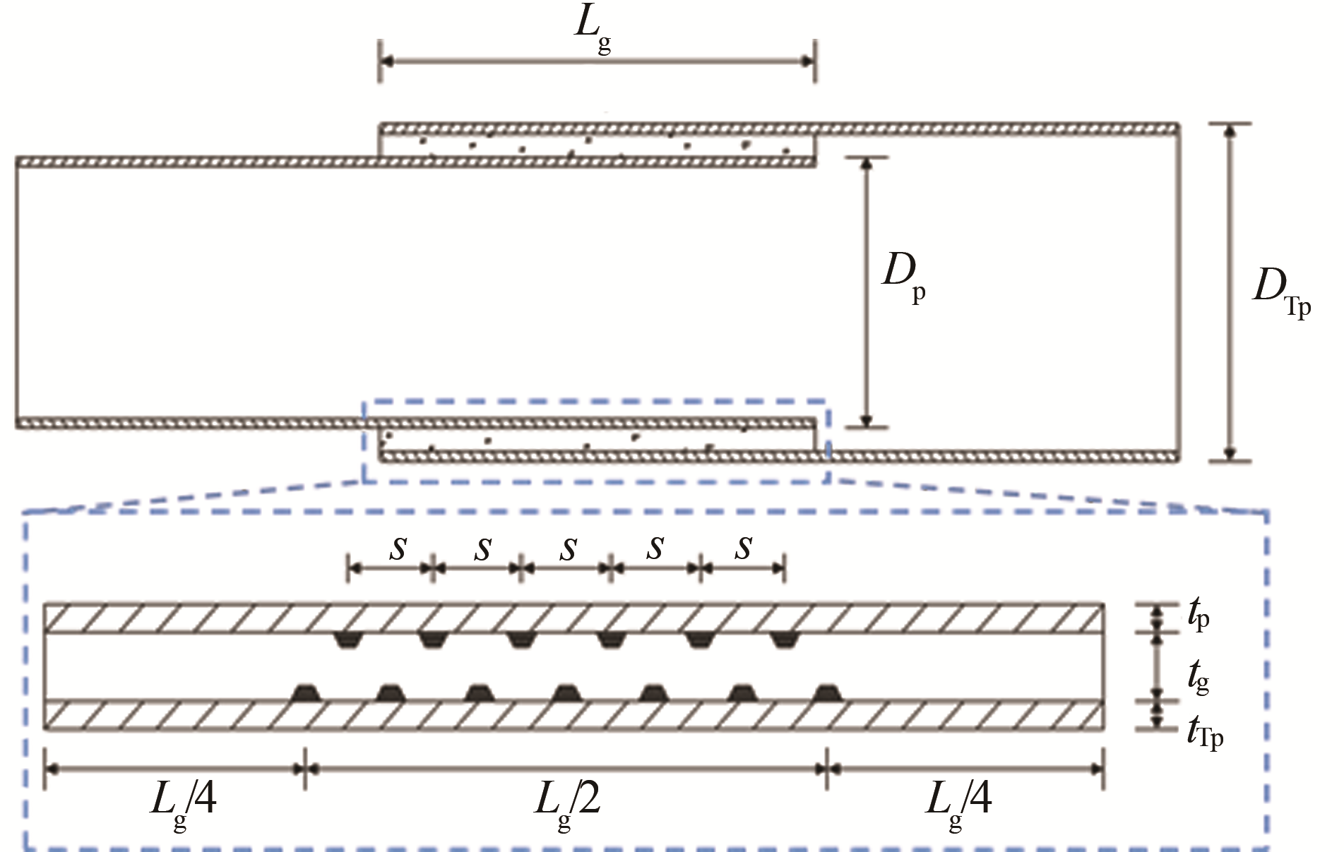
数值模型设计共考虑了三种参数,分别是灌浆层厚度tg(试件编号为GW-1~GW-4),灌浆连接段剪力键高距比h/s(试件编号为SW-1~SW-4),灌浆连接段长径比Lg/Dp(试件编号为LW-1~LW-4)。灌浆连接段数值分析的尺寸设计如表1所示,尺寸布置如图1所示。

Figure 1. Dimensions of the specimens of the grouted connections
试件编号 内钢管 外钢管 灌浆材料 灌浆连接段 剪力键 剪力键 长径比Lg/ Dp 高距比h/s 外径Dp/mm 厚度tp/mm 外径DTp/mm 厚度tTp/mm 厚度tg/mm 全长Lg/mm 高度h/mm 间距s/mm GW-1 5 500 92 5 800 62 88 8 250 16 600 1.5 0.027 GW-2 5 460 108 GW-3 5 420 128 GW-4 5 380 148 SW-1 5 500 92 5 800 62 88 8 250 16 400 1.5 0.040 SW-2 600 0.027 SW-3 800 0.020 SW-4 1 000 0.016 LW-1 5 500 92 5 800 62 88 6 600 16 600 1.2 0.027 LW-2 7 700 1.4 LW-3 8 800 1.6 LW-4 9 900 1.8 Table 1.
Numerical parameter design scheme of grouted connections -
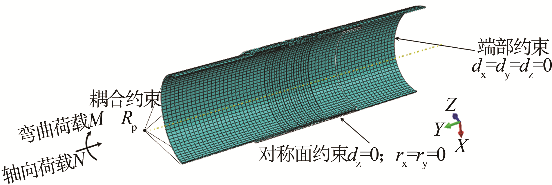
灌浆连接段数值模型与网格划分如图2所示。通过建立对称面约束的方式将模型简化为半模型,提高计算效率。本构关系方面,钢材采用两折线模型,灌浆料采用混凝土塑性损伤(CDP)模型[10]。建模方式采用分离体式建模,通过接触关系来定义钢管与灌浆料之间的相互作用,法向上定义为硬接触[11],切向上则采用库伦摩擦的方式进行定义[12]。在外钢管端部施加固定约束,并在内钢管端部定义参考点Rp,在参考点与内钢管顶面之间定义耦合约束,从而获得所需数据。

Figure 2. The numerical model and mesh of the grouted connections
数值模型的加载方式为先施加轴力到设定值,再施加弯矩。
1.1 数值模型参数设计
1.2 数值模型建立
-
本小节给出了各灌浆连接段试件在给定轴压比(n=0.036)情况下的弯矩-转角曲线,通过数据处理,得到的M-θ曲线反映了灌浆连接段整体的受力情况。
-
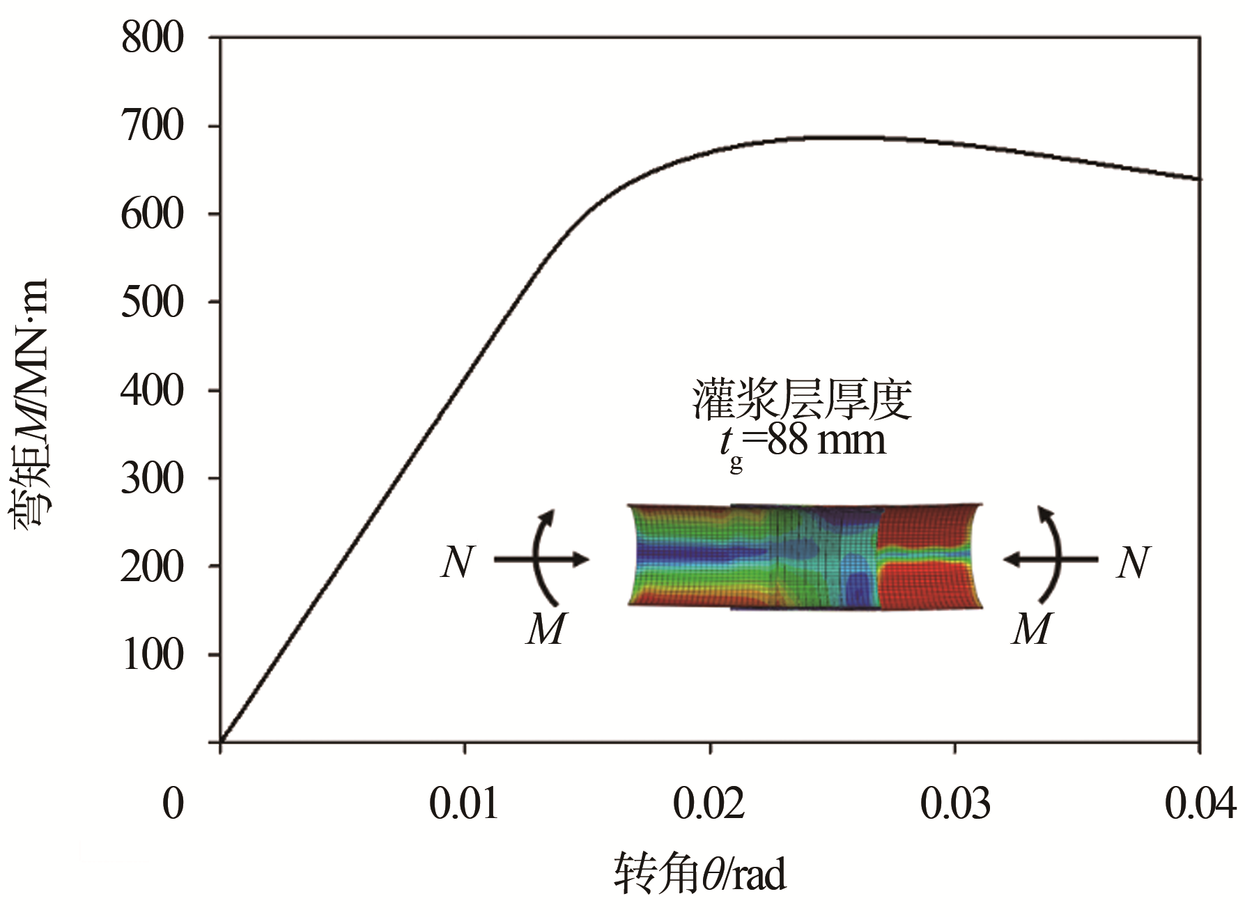
以GW-1为例,观察其M-θ曲线,如图3。曲线出现了明显的线性段和塑形段,表明灌浆连接段试件在轴力和弯矩共同作用下仍具有良好的延性。

Figure 3. Effect of grout thickness of GW-1 tg on M-θ curve
由表2可知,灌浆层厚度从88 mm增加到148 mm,灌浆连接段的极限抗弯承载力从687.3×10³ kN·m增加到747.3×10³ kN·m,提升了约8.7%。从工程实际应用的角度来看,灌浆料用量增加了近60%,但是抗弯承载力提升的比例却不到10%。因此,通过增加灌浆层厚度tg来提升抗弯承载力是非常不经济的做法。
试件编号 灌浆厚度tg /mm 峰值荷载My / (MN·m) 初始刚度 /(MN·m·rad-1) GW-1 88 687.3 41.3 GW-2 108 708.9 42.1 GW-3 128 725.9 42.3 GW-4 148 747.3 41.3 Table 2.
Analysis of key points and stiffness of M-θ curve of GW test piece in grouted connections 由于上部结构风机机组容量的增加,目前灌浆连接段存在大直径化的趋势,即灌浆连接段逐渐向薄壁结构靠拢。但是,由表2,计算结果显示GW-1~GW-4试件的M-θ曲线的初始刚度没有明显变化,灌浆层厚度tg的变化对灌浆连接段整体的抗弯刚度无明显影响。
-
在本次数值分析中,剪力键布置符合DNV-ST-0126规范的要求,并以此为前提增加剪力键的间距,剪力键的对数相应减少。由表3,灌浆连接段剪力键高距比h/s的变化对于灌浆连接段的极限承载力My和初始刚度均没有明显影响,这表明是目前现有的规范对于海上风机灌浆连接段的设计是非常保守的。
试件编号 剪力键高距比h/s 峰值荷载My / (MN·m) 初始刚度 /(MN·m·rad-1) SW-1 0.040 707.5 43.2 SW-2 0.027 712.2 42.2 SW-3 0.020 714.2 41.9 SW-4 0.016 710.0 41.1 Table 3.
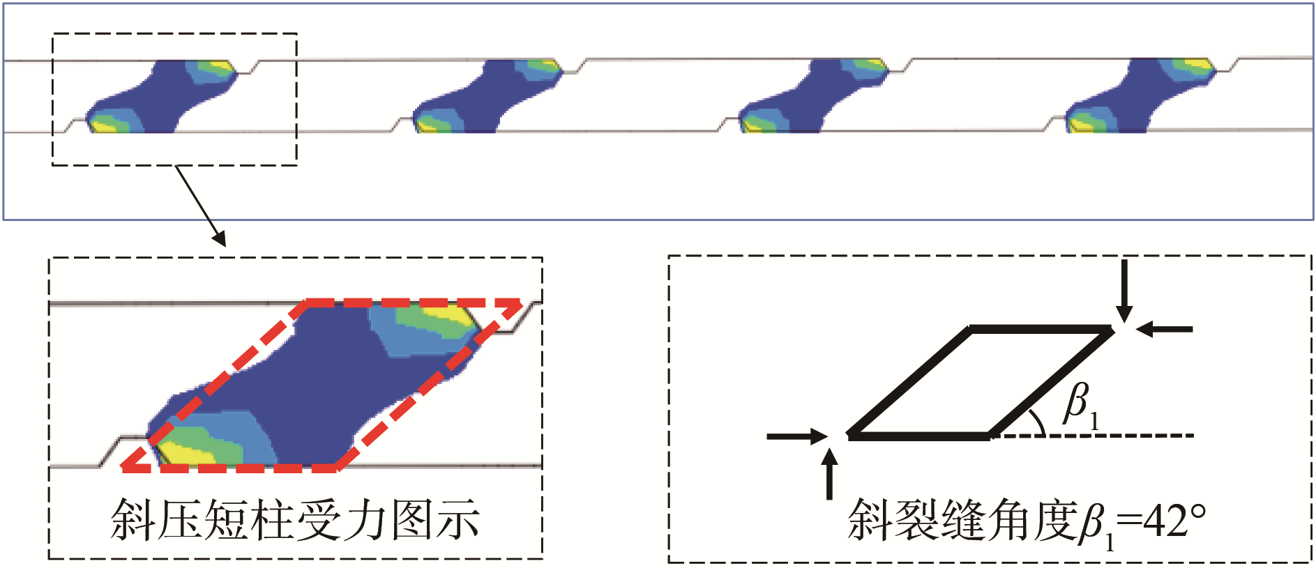
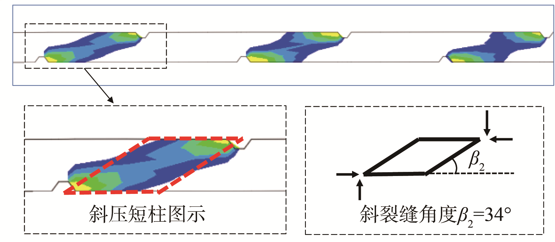
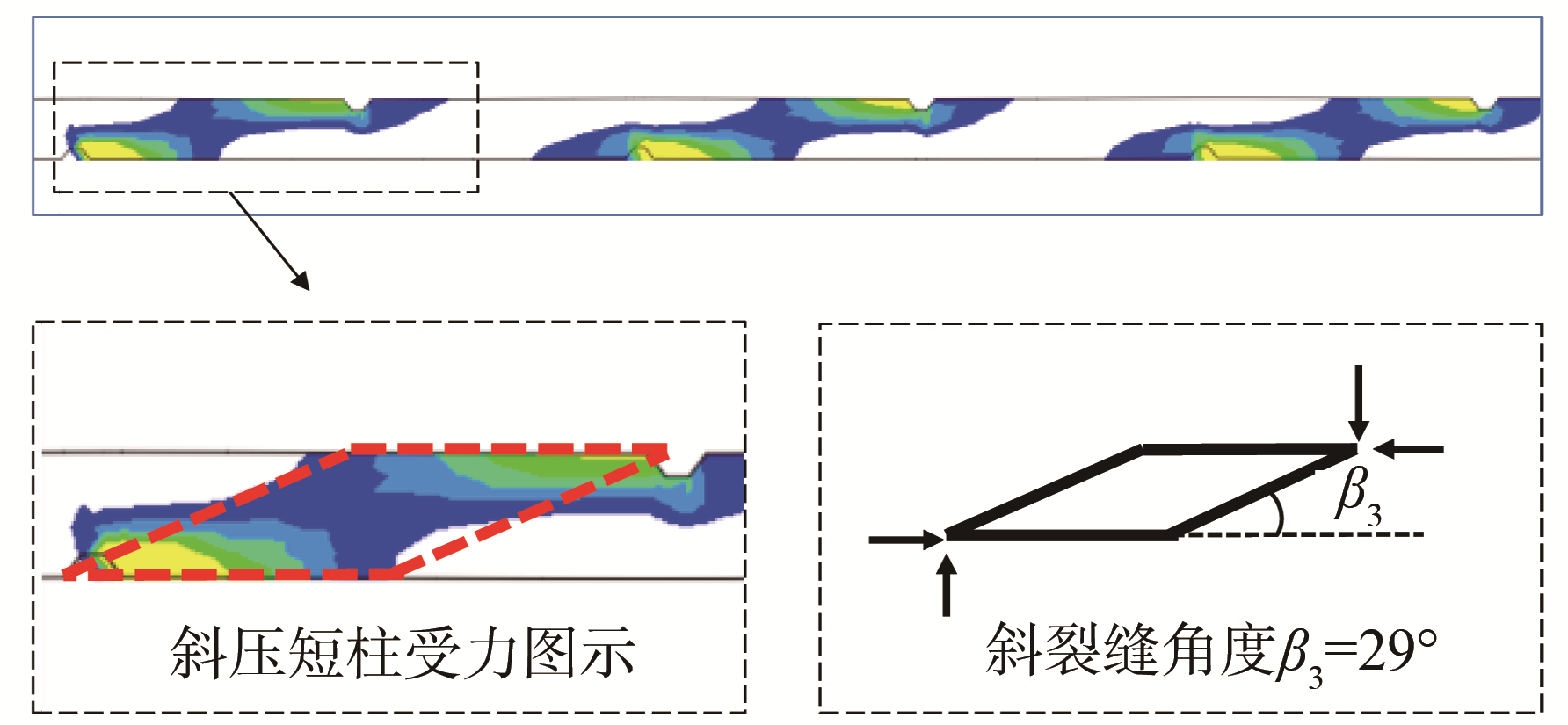
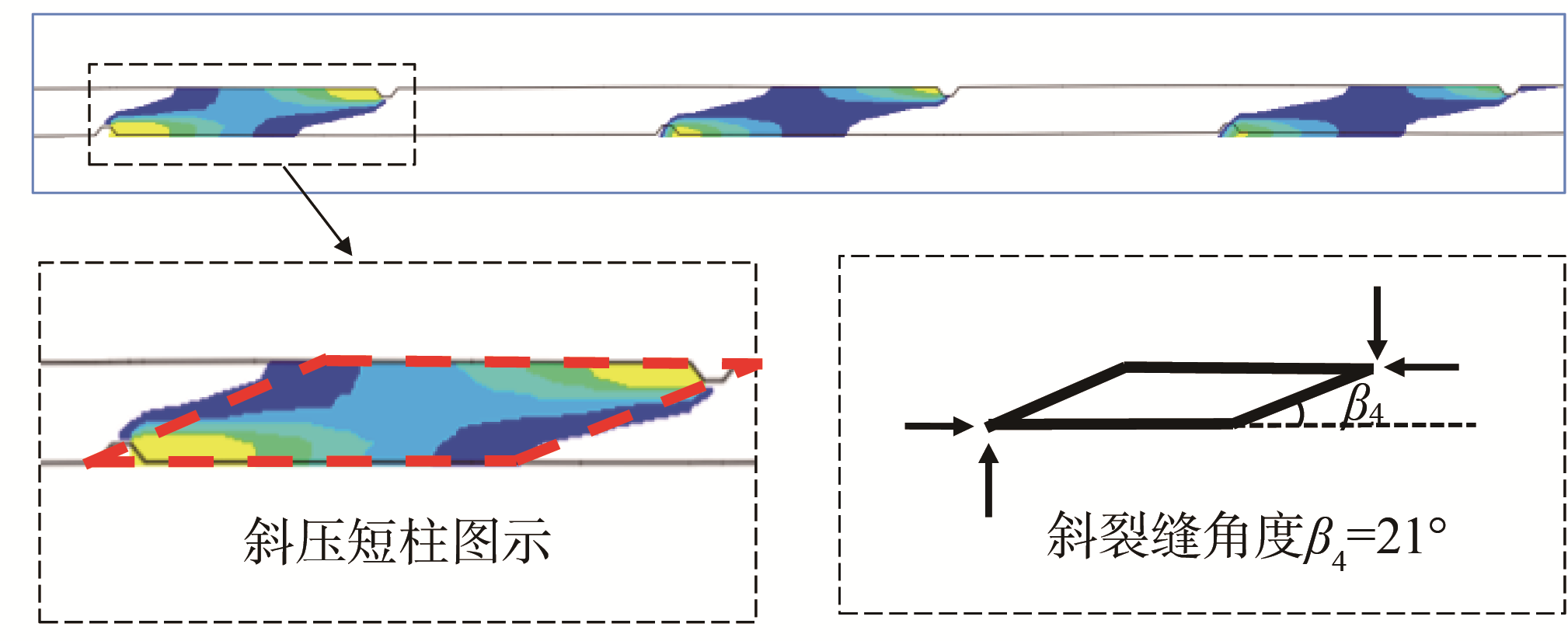
Analysis of key points and stiffness of M-θ curve of SW test piece in grouted connections 另一方面,剪力键高距比h/s对弯矩的传递机制有非常大的影响。灌浆层在剪力键之间的斜压短柱是传递压弯荷载的一个重要途径。如,受力斜压短柱与水平线的夹角和h/s之间存在明显的相关关系。在实际受力中,灌浆层裂缝的开展就是沿着斜压短柱的边缘线不断延伸,直到贯穿整个灌浆层。因此,受力斜压短柱与水平线的夹角也是灌浆连接段灌浆层开裂的斜裂缝角度。如图4所示,随着剪力键间距的不断增加,对应的灌浆层斜裂缝的角度越来越小。剪力键间距从400 mm增加到800 mm,对应的斜裂缝角度从42°减小到21°。

Figure 4. Influence of shear key Space on diagonal compression struts

Figure 4. Influence of shear key Space on diagonal compression struts

Figure 4. Influence of shear key Space on diagonal compression struts

Figure 4. Influence of shear key Space on diagonal compression struts
-
由表4可知,随着长径比L/Dp的增加,抗弯承载力不断提升。当长径比的值从1.2增加到1.8时,灌浆连接段的极限抗弯承载力My从615.1 MN·m增加到746.2 MN·m,提升了约21%,接触应力在长度增加的情况下得以充分发挥。同时可以发现,灌浆连接段长径比L/Dp的增加对于M-θ曲线的初始刚度和切线刚度也存在一定程度的影响。随着长径比L/Dp的增加,灌浆连接段整体的抗弯刚度有所提升。
试件编号 长径比L/Dp 峰值荷载My /(MN·m) 初始刚度 /(MN·m·rad-1) LW-1 1.2 615.1 33.1 LW-2 1.4 671.2 36.7 LW-3 1.6 706.2 39.8 LW-4 1.8 746.2 40.3 Table 4.
Analysis of key points and stiffness of M-θ curve of LW test piece in grouted connections
2.1 灌浆层厚度tg对M-θ曲线的影响
2.2 剪力键高距比h/s对M-θ曲线的影响
2.3 长径比L/Dp对M-θ曲线的影响
-
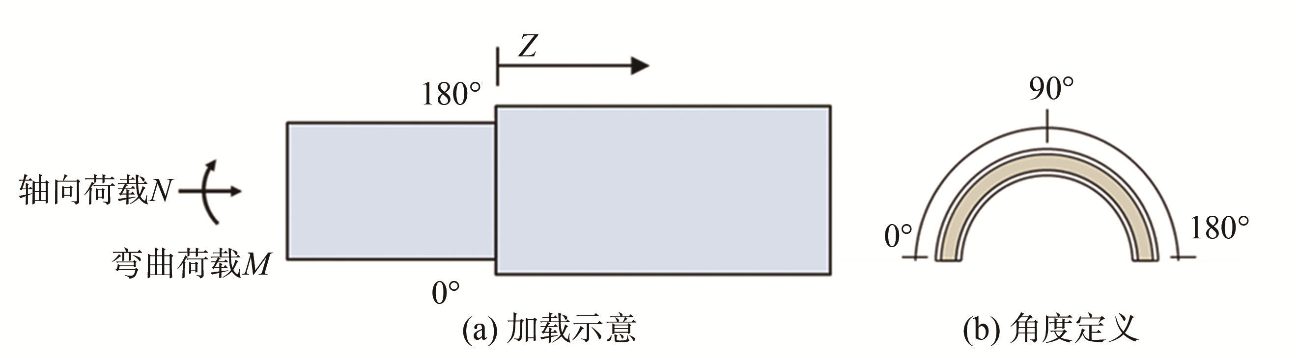
DNV规范并没有给出灌浆连接段在达到极限受力状态时的压弯承载力计算公式,而是通过控制灌浆连接段端部峰值接触压力P0不大于1.5 MPa这一准则,同时校核每一个剪力键的受力,以此确保灌浆连接段在设计荷载作用下的安全。因此,了解灌浆连接段在端部位置处钢管与灌浆料之间的相互作用是非常重要的。
灌浆连接段受拉侧定义为0°,受压侧定义为180°,如图5所示。沿着灌浆连接段灌浆体端部的内表面环向均匀等分,提取11个单元的接触压力。单元的接触压力是其接触表面对应四个点的接触压力的平均值。

Figure 5. Definition of angle coordinate system of grouted connections
-
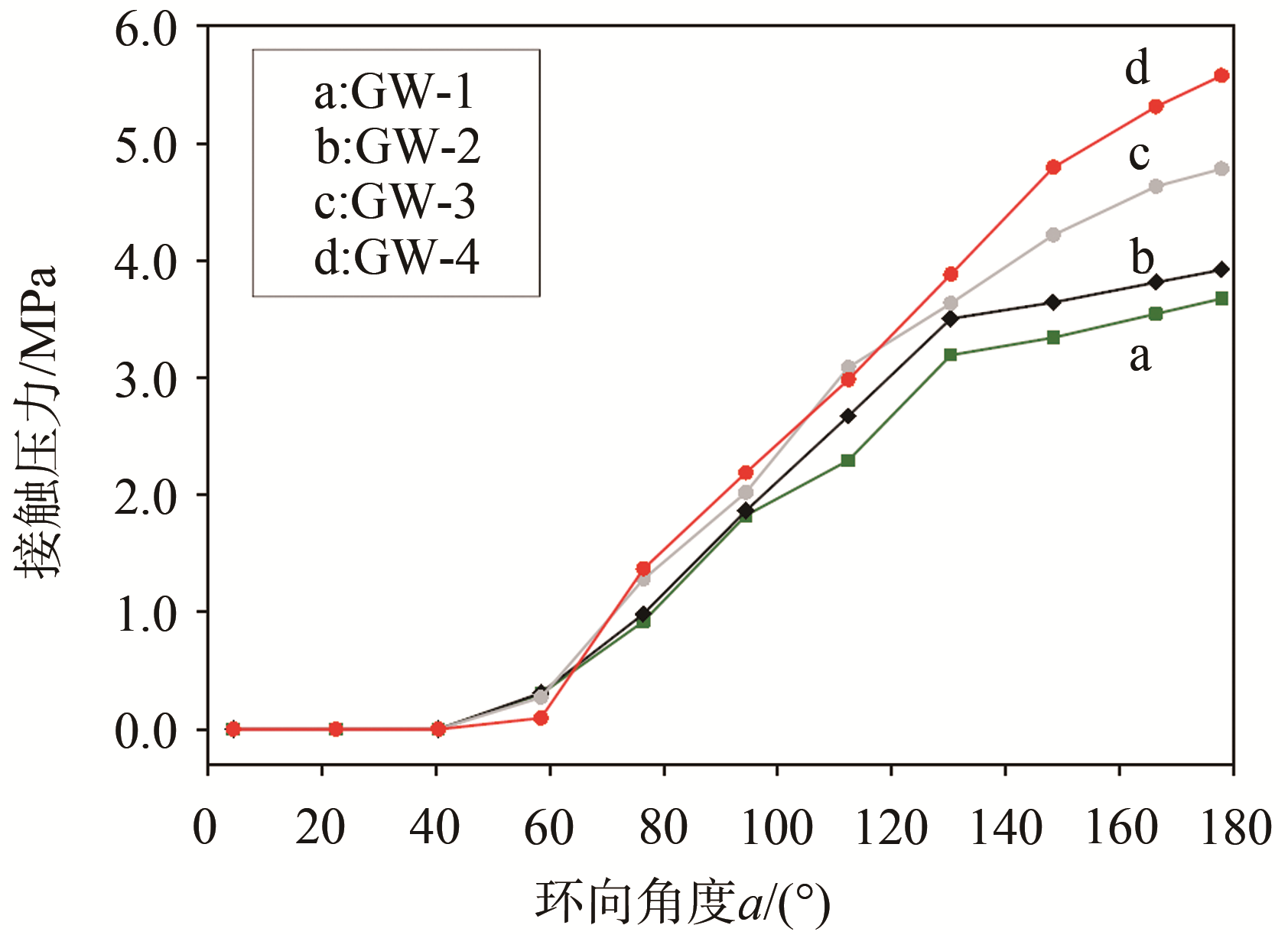
随着灌浆层厚度tg的增加,灌浆连接段径向刚度不断提升,因此端部接触压力的值不断增加,如图6所示。当灌浆层厚度tg从88 mm增加到148 mm时,受压侧180°位置处的接触压力峰值从3.7 MPa增加到5.57 MPa,这表明接触压力所提供的抗弯承载力组分有所提升。

Figure 6. Effect of tg on circumferential contact pressure distribution at the end of grouted connections
-
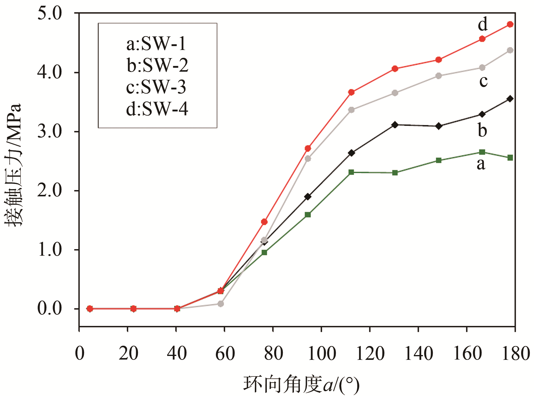
由图7可知,随着灌浆连接段剪力键高距比h/s的不断减小,灌浆连接段端部的接触应力不断增大。当灌浆连接段的剪力键高距比h/s从0.040减小到0.016时,受压侧180°位置处的接触压力峰值从2.6 MPa增加到4.8 MPa,这表明接触压力所提供的抗弯承载力组分Mp有所提升。高距比h/s的减小意味着剪力键对数的减少,进而导致剪力键对于抗弯承载力的贡献降低,因此,接触压力所提供的抗弯承载力组分Mp有所提升。

Figure 7. Effect of h/s on circumferential contact pressure distribution at the end of grouted connections
-
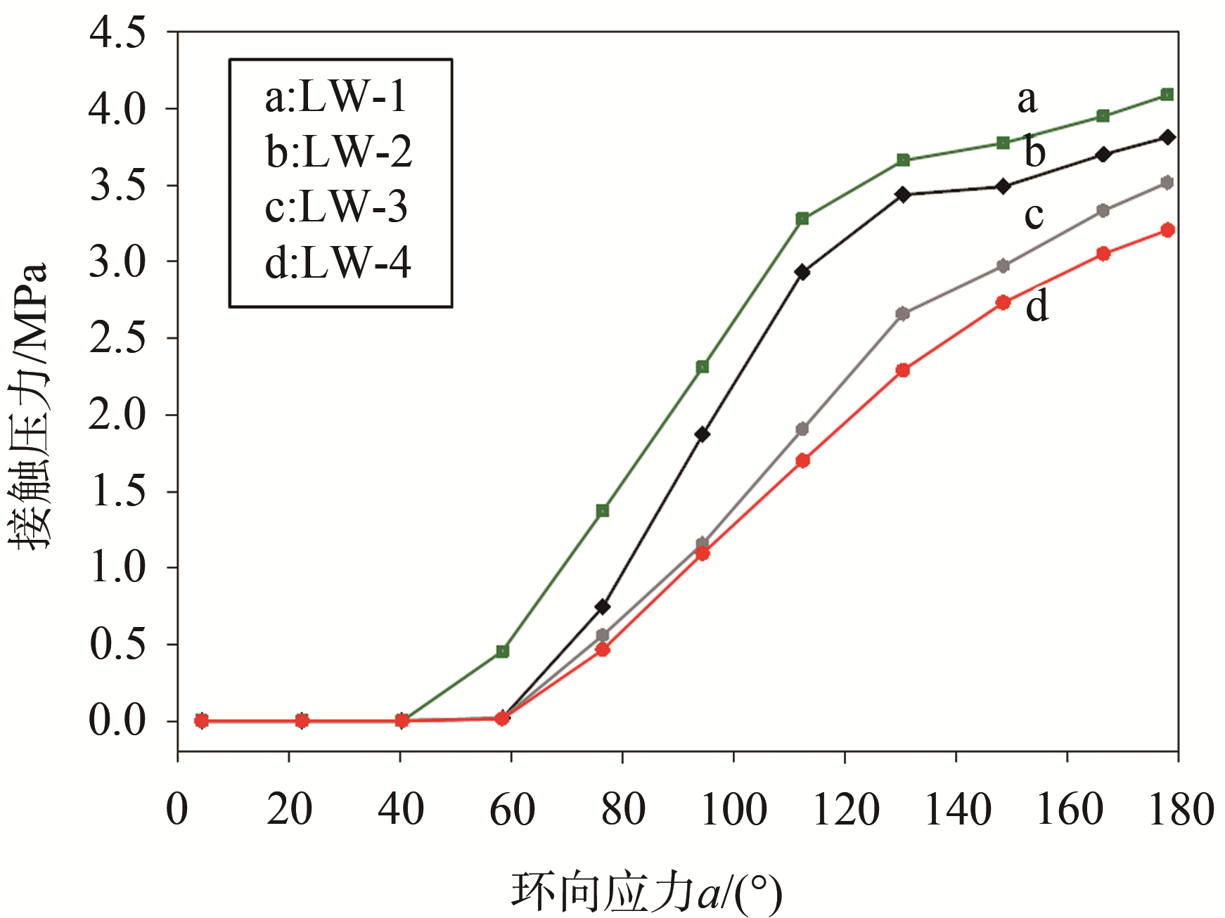
试件LW-1~LW-4处于极限抗弯承载力时的端部环向接触压力的分布规律如图8所示,随着长径比的增大,接触压力不断减小。当灌浆连接段的长径比L/Dp从1.2增加到1.8时,受压侧180°位置处的接触压力峰值从4.1 MPa减小到3.2 MPa。

Figure 8. Effect of L/Dp on circumferential contact pressure distribution at the end of grouted connections
3.1 灌浆层厚度tg对端部接触压力分布的影响
3.2 剪力键高距比h/s对端部接触压力分布的影响
3.3 长径比L/Dp对端部接触压力分布的影响
-
本小节对灌浆连接段在轴力和弯矩共同作用下的应力状态进行分析,主要采用钢管最大Mises应力、灌浆层最大Tresca应力、名义平均应力σN以及应力相关系数ηcor四个指标进行评估。
通过引入名义平均应力σN的概念[13],并以此评估灌浆连接段在压-弯受力作用下的受力性能。其定义为,灌浆连接段的受压侧(180°位置处)的外钢管在其有效破坏长度内的应力均值。有效破坏长度le和应力相关系数ηcor定义如下,如式(3)~式(5):
((1)) 在上式中,参数Rt用于考虑径厚比的影响,其计算表达式如下:
((2)) 式中:v为泊松比;σy为屈服应力(MPa);d为钢管的直径(mm);t为钢管的厚度(mm)。
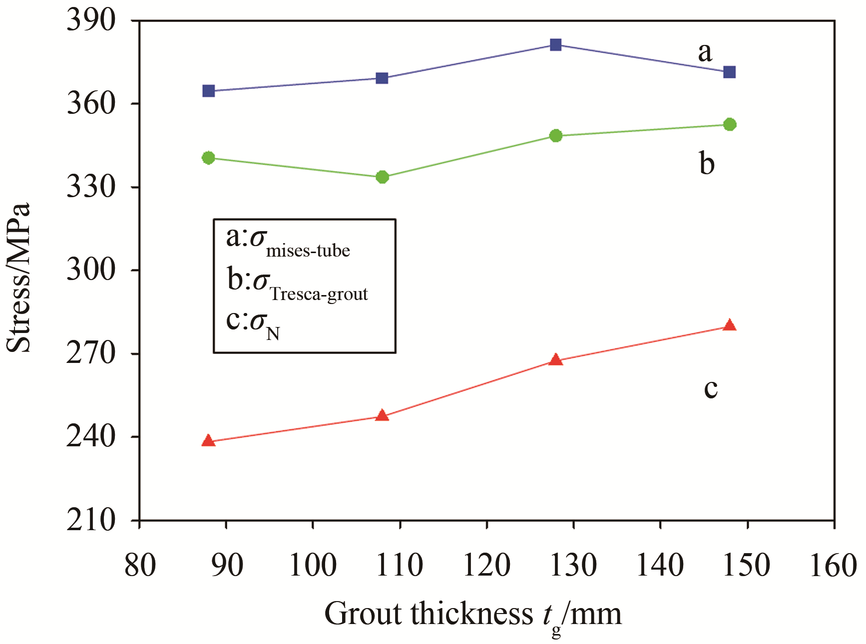
((3)) 在给定轴压比(n=0.036)的情况下,灌浆连接段试件达到极限抗弯承载力时所对应的的钢管最大Mises应力、灌浆层的最大Tresca应力、名义平均应力σN的具体值如图9~图11所示。

Figure 9. Effect of tg on stress state of grouted connections

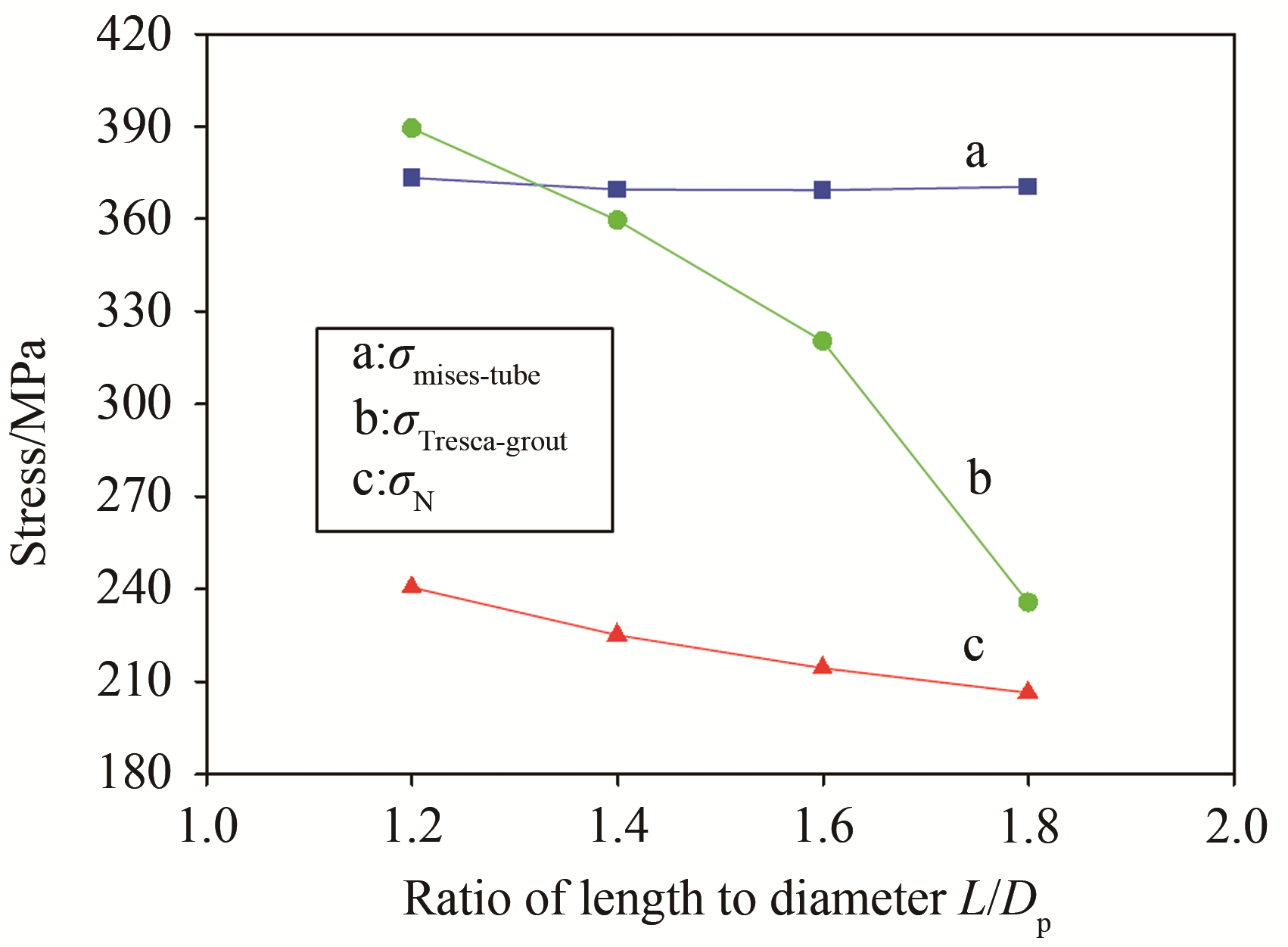
Figure 10. Effect of L/Dp on stress state of grouted connections

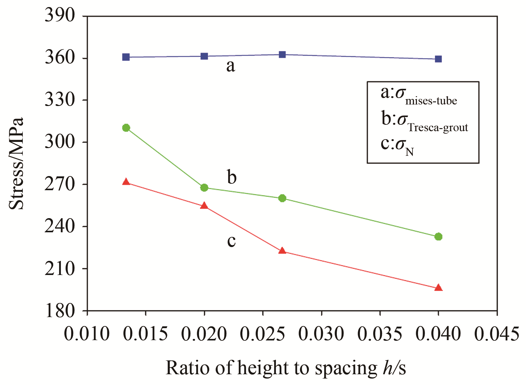
Figure 11. Effect of h/s on stress state of grouted connections
在灌浆层厚度方面,如图9,随着灌浆层厚度tg的增加,灌浆层的名义平均应力σN均出现增大的趋势。当灌浆层厚度tg从88 mm增加到148 mm时,名义平均应力σN的值从238.2 MPa上升到279.7 MPa,增加了约17.4%。而钢管最大Mises应力以及灌浆层的最大Tresca应力没有呈现出明显的变化规律。这说明随着灌浆层厚度的增加,其应力分布将会更加集中。
在长径比方面,如图10,随着长径比L/Dp的不断增加,灌浆层的峰值Tresca应力以及名义平均应力σN均出现减小的趋势。当长径比L/Dp的值从1.2增加到1.8时,灌浆层的最大Tresca应力从389.3 MPa减小到235.5 MPa,降低了约39.5%,而名义平均应力σN则降低了14.1%。数值计算结果表明,长径比L/Dp的增加使得灌浆连接段以一种更加平缓的方式传递轴力和弯矩,灌浆料的应力集中现象有所缓和,灌浆连接段整体的应力水平降低,而钢管最大Mises应力的值维持在360 MPa的水平。
在剪力键高距比方面,如图11,随着剪力键的高距比h/s的不断增加,有效剪力键对数有所提升,剪力键数量的提升使得单个剪力键的受力在降低,因此灌浆层的峰值Tresca应力以及名义平均应力σN均出现减小的趋势。当剪力键高距比h/s的值从0.013增加到0.04时,灌浆层的最大Tresca应力从310.2 MPa减小到232.6 MPa,降低了约25%,而名义平均应力σN则降低了27.7%。
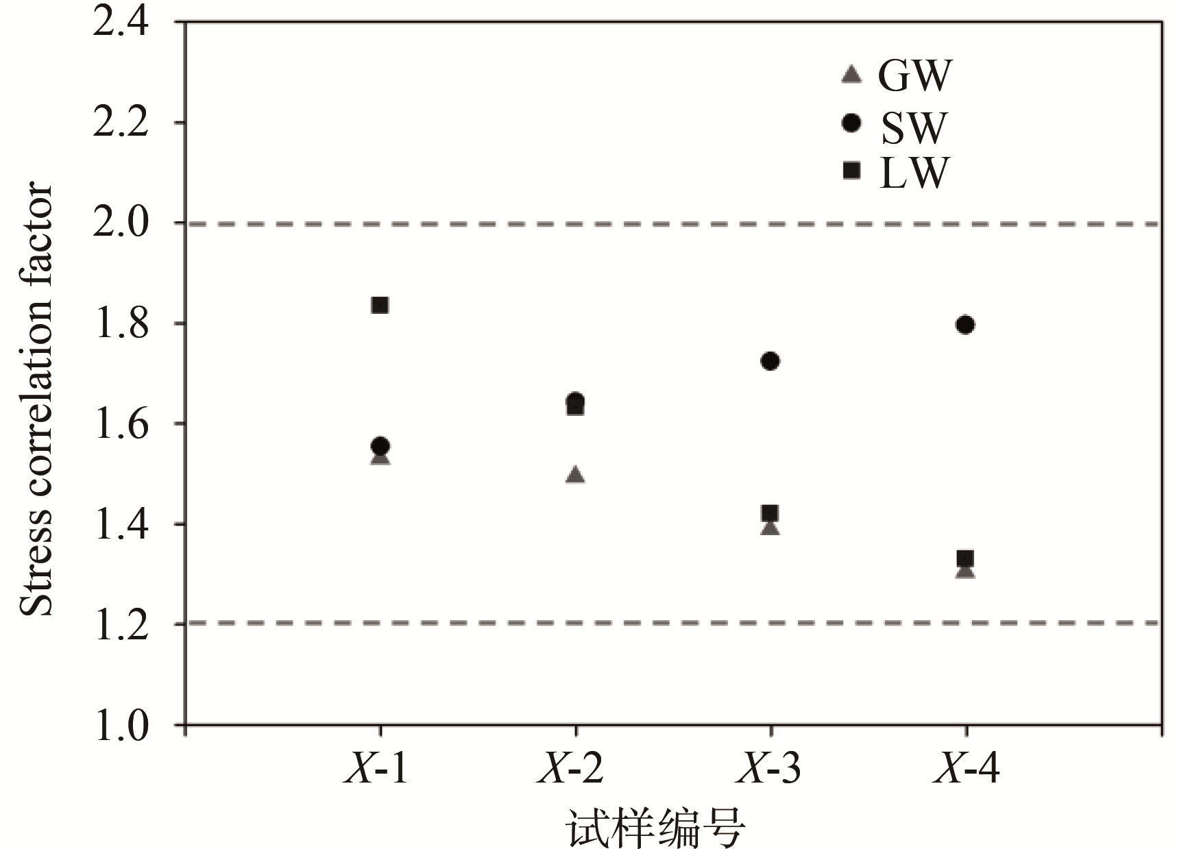
进一步对所得数据汇总,得到灌浆连接段在轴力和弯矩共同作用下的应力相关系数ηcor 如图12所示。前已述及,应力相关系数ηcor 用于表征灌浆连接段钢管最大Mises应力与灌浆连接段名义平均应力σN之间的关系。计算结果表明,在给定轴压比(n=0.036)的情况下,灌浆连接段达到极限抗弯承载力时的应力相关系数ηcor变化范围在1.2~2.0之间,本计算结果可为实际工程设计提供参考。

Figure 12. Stress correlation factor ηcor of grouted connections under axial force and bending moment


-
本文对灌浆连接段在轴力和弯矩共同作用下的受力性能进行了讨论分析,重点探讨了灌浆层厚度tg、剪力键高距比h/s和长径比L/Dp三个参数,并得到如下结果:
1)在给定轴压比(n = 0.036)的情况下,灌浆连接段的M-θ 曲线表现出良好的延性。随着灌浆层厚度tg 的增加,灌浆连接段的极限抗弯承载力Mu存在一定程度的提升。长径比L/Dp的增加对于灌浆连接段的极限抗弯承载力Mu同样存在有利影响。灌浆连接段剪力键高距比h/s的变化对于灌浆连接段的极限承载力Mu没有明显影响,但是对灌浆层斜裂缝角度的形成存在显著影响。
2)随着灌浆层厚度tg的增加,灌浆连接段的端部接触压力峰值不断提升。灌浆连接段剪力键高距比h/s的不断减小,灌浆连接段端部的接触压力同样存在不断增大的趋势。随着灌浆连接段的长径比L/Dp的不断增加,灌浆连接段端部的接触压力不断减小。
3)灌浆连接段的名义平均应力σN和灌浆层最大Tresca应力均随着灌浆层厚度tg的增加而不断增加。随着长径比L/Dp的不断增加,灌浆层的峰值Tresca应力以及名义平均应力σN均出现减小的趋势。随着剪力键的高距比h/s的不断增加,灌浆层的峰值Tresca应力以及名义平均应力σN均出现减小的趋势。在给定轴压比(n=0.036)的情况下,灌浆连接段达到极限抗弯承载力时的应力相关系数ηcor 变化范围在1.2~2.0之间。

 DownLoad: