• Peer Review
  • Non-profit
  • Global Open Access
  • Green Channel for Rising Stars
Volume 7 Issue S2
Jan.  2021
Turn off MathJax
Article Contents

Qian XIONG, Chenggang DENG, Zhangwei SUN. Analysis and Discussion on Influencing Factors of U-shaped Water Seal Operation of Gland Seal Heater[J]. SOUTHERN ENERGY CONSTRUCTION, 2020, 7(S2): 101-106. doi: 10.16516/j.gedi.issn2095-8676.2020.S2.016
Citation: Qian XIONG, Chenggang DENG, Zhangwei SUN. Analysis and Discussion on Influencing Factors of U-shaped Water Seal Operation of Gland Seal Heater[J]. SOUTHERN ENERGY CONSTRUCTION, 2020, 7(S2): 101-106. doi: 10.16516/j.gedi.issn2095-8676.2020.S2.016

Analysis and Discussion on Influencing Factors of U-shaped Water Seal Operation of Gland Seal Heater

doi: 10.16516/j.gedi.issn2095-8676.2020.S2.016
  • Received Date: 2018-11-24
  • Rev Recd Date: 2020-12-02
  • Publish Date: 2021-01-08
  •   Introduction   During the actual operation of the power plant, due to the inaccurate calculation of the effective height of the water seal, the water seal was pulled or worn, or the water seal was not well drained, thus affected the economic and safe operation of the unit.  Method  In order to provide a more accurate calculation of the effective height of the water seal in the subsequent works, the influencing factors were analyzed and discussed which were the position of the water seal, the structural size of the water seal, the back pressure change of the condenser, the pressure change of the shaft seal fan and the hydrophobic vaporization.  Result  The influencing factors of the above factors on the calculation of the effective height of the water seal are obtained. When calculating the effective length of the U-shaped water seal, the influence of the above influencing factors needs to be comprehensively considered, the initial calculation value is corrected, and the height of the multi-level water seal is reasonably selected.  Conclusion  So as to solve the problems occurring at the scene,and the guiding opinions and precautions for design, construction and commissioning are proposed.
  • [1] 吕红樱. 水封高度的一种计算方法 [J]. 重庆电力高等专科学校学报. 2005, 10(4):11-13+18.

    LVH Y. A calculation method for the height of the water seal [J]. Journal of Chongqing Electric Power College,2005,10(4):11-13+18.
    [2] 谭灿燊, 吴阿峰. 多级水封器高度计算方法的探讨 [J]. 节能, 2009,28(1): 23-24.

    TANC S. WU A F. Discussion on calculation method of multi-level water sealer height [J]. Energe Saving, 2009,28(1): 23-24.
    [3] 陆杰. U型水封筒改造对真空严密性的影响 [J]. 电力与能源,2018,39(4): 576-577.

    LUJ. Influence of U-shaped water seal cylinder modification on vacuum tightness [J]. Electricity and Energy,2018, 39(4): 576-577.
    [4] 郝阳阳. 轴封加热器疏水系统节能改造探讨 [J]. 采矿技术,2016,16(3):98-99.

    HAOY Y. Discussion on energy saving reform of shaft seal heater drainage system [J]. Mining Technology, 2016,16(3):98-99.
    [5] 洪立,王晓文. 给水泵密封水回水多级水封装置改造 [J]. 华电技术.2015,37(3): 31-33.

    HONGL. WANG X W. Reconstruction of multi-stage water seal device for feed water pump sealing water return water [J]. Huadian Technology. 2015,37(3): 31-33.
    [6] 李秀江. 火力发电厂轴加和多级水封系统应用研究 [J]. 中国高新技术企业,2016(14): 43-44.

    LIX J. Application research on shaft seal heater and multi-stage water seal system in themal power plant [J]. China High-tech Enterprises,2016(14): 43-44.
    [7] 宁珂. 机组正常运行时轴加疏水水封失去原因分析 [J]. 工业技术,2016(8): 71-72.

    NINGK. Analysis of loss of shaft seal heater and hydrophobic water in normal operation of unit [J]. Industrial Technology, 2016(8): 71-72.
    [8] 靖长财. 1 000 MW机组轴封加热器水位控制的方案分析与建议 [J]. 电站辅机,2017(2): 39-40+47.

    JINGC C.Analysis and suggestion of scheme for water level control of shaft seal heater for 1 000 MW unit [J]. Power Station Auxiliary Machine,2017(2): 39-40+47.
    [9] 郭义杰. 我厂给水泵U型水封运行工况下存在问题分析 [J]. 科技信息,2010(13): 781-782.

    GUOY J. Analysis of problems existing in U-type water seal operation condition of feed pump of our factory [J]. Science & Technology Information,2010(13): 781-782.
    [10] 颜云. 轴封加热器疏水系统优化改造探讨 [J]. 中国新技术新产品.2012(16): 130-131.

    YANY. Discussion on optimization and modification of shaft seal heater drainage system [J]. China New Technologies and Products,2012(16): 130-131.
  • 通讯作者: 陈斌, bchen63@163.com
    • 1. 

      沈阳化工大学材料科学与工程学院 沈阳 110142

    1. 本站搜索
    2. 百度学术搜索
    3. 万方数据库搜索
    4. CNKI搜索

Figures(4)  / Tables(6)

Article Metrics

Article views(386) PDF downloads(19) Cited by()

Related

Analysis and Discussion on Influencing Factors of U-shaped Water Seal Operation of Gland Seal Heater

doi: 10.16516/j.gedi.issn2095-8676.2020.S2.016

Abstract:   Introduction   During the actual operation of the power plant, due to the inaccurate calculation of the effective height of the water seal, the water seal was pulled or worn, or the water seal was not well drained, thus affected the economic and safe operation of the unit.  Method  In order to provide a more accurate calculation of the effective height of the water seal in the subsequent works, the influencing factors were analyzed and discussed which were the position of the water seal, the structural size of the water seal, the back pressure change of the condenser, the pressure change of the shaft seal fan and the hydrophobic vaporization.  Result  The influencing factors of the above factors on the calculation of the effective height of the water seal are obtained. When calculating the effective length of the U-shaped water seal, the influence of the above influencing factors needs to be comprehensively considered, the initial calculation value is corrected, and the height of the multi-level water seal is reasonably selected.  Conclusion  So as to solve the problems occurring at the scene,and the guiding opinions and precautions for design, construction and commissioning are proposed.

Qian XIONG, Chenggang DENG, Zhangwei SUN. Analysis and Discussion on Influencing Factors of U-shaped Water Seal Operation of Gland Seal Heater[J]. SOUTHERN ENERGY CONSTRUCTION, 2020, 7(S2): 101-106. doi: 10.16516/j.gedi.issn2095-8676.2020.S2.016
Citation: Qian XIONG, Chenggang DENG, Zhangwei SUN. Analysis and Discussion on Influencing Factors of U-shaped Water Seal Operation of Gland Seal Heater[J]. SOUTHERN ENERGY CONSTRUCTION, 2020, 7(S2): 101-106. doi: 10.16516/j.gedi.issn2095-8676.2020.S2.016
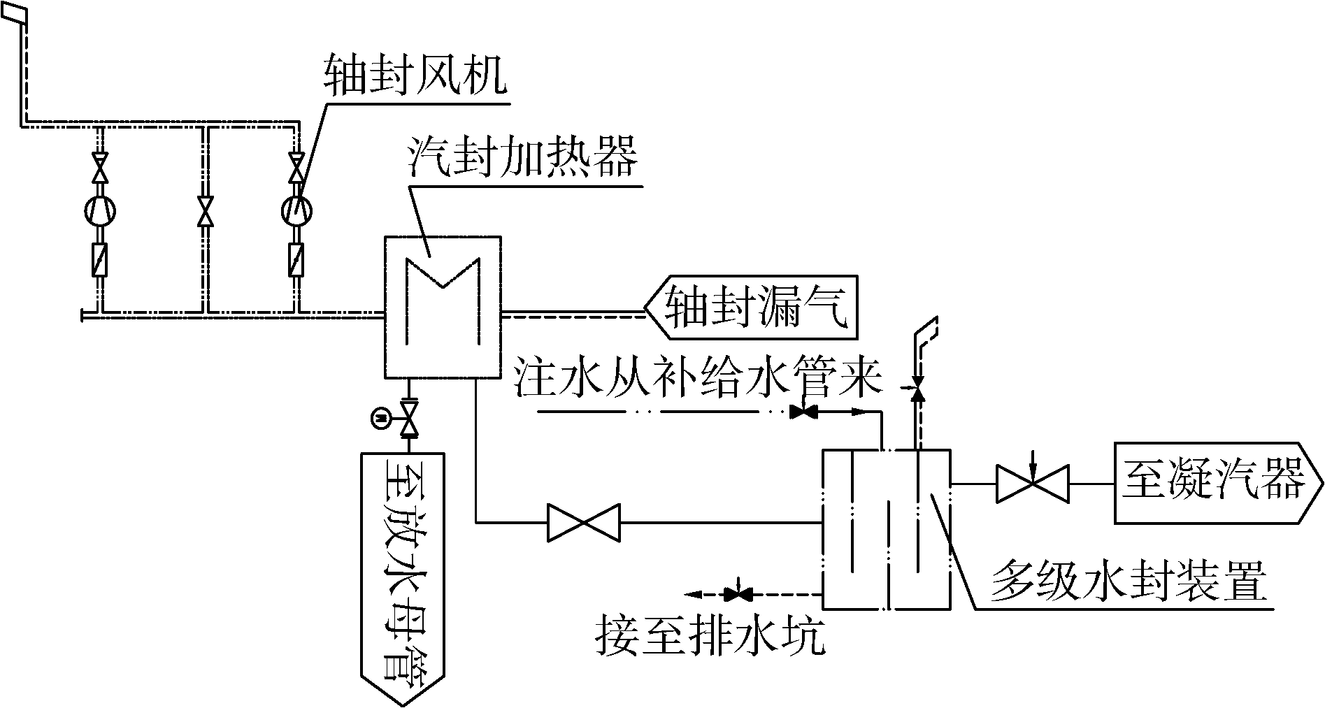
  • 火力发电厂轴封加热器水封是汽轮机轴封加热器的一种疏水装置,利用水封的阻力及水柱高差等平衡轴封加热器和凝汽器之间的压差,使轴封加热器的疏水回收至凝汽器中。U型水封通常分为多级和单级水封。单级水封通常为埋地,开挖深,易腐蚀,难维护。多级水封则具有空间占地小,容易施工等特点,但多级水封的主要难点在于多级水封的有效长度的计算。多级U型水封的有效长度的准确性直接关系电厂的经济运行。U型水封疏水不畅,如轴封加热器水位持续过高,达到轴封风机的进口,则轴封风机抽出的不是不凝结的气体,从而增加轴封风机的负荷,严重时使轴封风机由于过负荷而被烧毁。如果U型水封失水,则轴封加热器的水位无法稳定保持,持续下降,最终使得轴封蒸汽冷却器的汽测直接与凝汽器相通,机组真空下降,机组热效率降低。如轴封加热器疏水由于U型水封无法投入,而走危急疏水直排地沟,疏水不进入凝汽器,则该部分能量损失使得机组的经济性有所下降。因此有必要对水封结构,前后设备背压变化对水封有效高度的影响进行研究分析,得出影响因素,以使对后续的设计,施工及调试过程出现的问题提供指导意见及注意事项。

  • 轴封加热器的作用是利用汽轮机轴封系统漏出的蒸汽来加热凝结水,提高凝结水温度,减少轴封漏气的热损失。轴封风机将不凝结的气体排出,并使汽轮机轴封漏气系统的压力维持在负压。工作过程如图1所示。

    Figure 1.  U-type water seal working principle

    U型水封的作用是利用水封的水柱高差平衡两容器间的压差,U型水封的设计是一个复杂的计算工程,水封高度的计算尤为重要。U型水封的典型结构型式如图2所示。

    Figure 2.  Structure diagram of U-shaped water seal

  • 对U型水封的计算通常分为两种,静态的计算方法和动态的计算方法。

  • 静态的计算方法是根据水封的放置位置求解出第一级水封的压力值,依次后几级则是根据理想气体状态方程,根据已有的第一级的水封压力值及第2级的水封空气体积即可求出第2级水封的压力值,然后依次求解后几级的水封压力值,通过该方法可以计算得出各级水封有效水头的高度值1

  • 动态计算方法的原理是U型水封在工作时,受疏水中夹带的空气及空气的可流动性的影响,各级水封里的空气体积量是变化的。动态的计算方法则是通过调节每级水封空气体积来调节该级水封的有效高度,从而使每级水封的高度相当,使各级最大高度之和满足总水头要求2

    水封高度计算公式:

    H=Pin-Poutnρ+0.5~1/n ((1))

    式中:H为多级水封中每级水封管的高度;Pin,Pout分别为多级水封进口/出口的压力(MPa);n为多级水封的水封级数;ρ为水重;(0.5~1)为富裕度。

    无论是静态计算方法或是动态计算方法,都未对水封的有效高度计算的影响因素计算分析。动态的计算方法需要保证有足够的空气体积满足水封压力的变化需求。

    以某工程水封实际运行参数为例来计算多级水封的高度值。根据汽轮机运行规范,轴封风机的压力通常要求为-2~3 kPa,因此Pin=97 kPa,Pout=7.4 kPa,按照动态的计算方法,计算3级水封各级水封的高度值。

    Pin-Poutnρ=2.98m ((2))

    考虑富裕度0.5~1/n,富裕度按照最大0.33 m,则每级水封的高度取为3.3 m则满足要求。

  • 对于三级多级水封来说,水封底部放置的位置与凝汽器接口的高差对水封有效高度的影响如表3所示。

    U型水封底部与凝汽器接口高差/mh2/mh3/m
    03.85.4
    13.25
    22.74.5
    32.34
    41.83.5
    4.21.73.3
    51.42.9
    61.12.2
    70.71.5

    Table 3.  U-shaped water seal effective height with position data sheet

    表3的计算来看,当水封放置的位置与凝汽器接口的相对高差小于4.2 m时,则上述水封高度则不满足运行的需要。水封的有效高度是否够用和水封放置的位置有很大关系。

  • 对于相同的水封进出口压力,由于水封筒径大小的变化,水封第三级所需的高度随筒径增大而逐渐减小;因此对于相同的水封高度而言,选择越大的水封筒径对水封的有效高度越有利。如表4表5所示。

    放置高差/m水封筒外径/mm
    133159219273325
    02.633.84.55.1
    12.12.53.23.84.4
    21.722.73.33.8
    31.61.62.32.73.2
    411.31.82.22.6
    50.80.91.41.62
    60.60.81.11.31.5
    70.40.50.70.91.1

    Table 4.  Data sheet of effective height value h2 required for the second stage water seal with the diameter of the cylinder

    放置高差/m水封筒外径/mm
    133159219273325
    06.76.35.44.74.1
    16.25.854.43.8
    25.65.34.53.93.4
    34.74.743.53
    44.343.532.6
    53.43.32.92.52.1
    62.72.52.21.91.6
    71.91.81.51.31.1

    Table 5.  Data sheet of effective height value h3 required for the third stage water seal with the diameter of the cylinder

  • 凝汽器的背压随循环水温的变化而变化,冬季时循环水的水温较低,对应的凝汽器的背压也越低,而夏季时循环水温升高,凝汽器的背压也升高。在计算U型水封的高度时,我们通常选择凝汽器的额定背压作为输入项进行水封高度的计算。随着凝汽器背压的降低,水封所需的高度也逐步增加。当实际凝汽器背压低于额定背压值时,则原有设计的水封高度则不满足运行的需要。如表6所示。

    凝汽器背压/kPah2 /mh3 /m
    223.6
    41.853.5
    51.83.48
    7.41.73.3
    11.81.553.03

    Table 6.  Influence of condenser back pressure on effective height of water seal

  • 随着轴封风机的压力升高,水封所需的高度也逐步增加。原有的水封高度已不满足运行的需要。因此在水封高度计算时,可直接将轴封风机的压力取为大气压,这样对水封高度计算留有一定的裕量。如表7所示:

    轴封风机压力/kPah2 /mh3 /m
    971.73.3
    981.73.4
    991.73.5
    1001.73.6

    Table 7.  Influence of pressure change of shaft seal fan on effective height of water seal

  • 根据伯努利方程

    P1ρ1g+w122g+z1=P2ρ2g+w222g+z2+hw ((3))

    式中:P1P2为水封进出口静压力(Pa);ρ1ρ2为水封进出口密度(kg/m3);w1w2为水封进出口速度(m/s);z1z2-水封进出口位能(m);hw-沿程阻力损失(m)。

    由于z2-z1即为水封高度H,整理上式得:

    H=1gp1ρ1-p2ρ2+12gw12-w22-hw ((4))

    由于动压能12g(w12-w22)的值很小,可忽略不计,则:

    H=P1ρ1g-P2ρ2g-hw ((5))

    如果对于多级水封,则:

    H=1n(P1ρ1g-P2ρ2g-hw) ((6))

    因此需要考虑进出口疏水密度的变化,由于疏水的汽化,则疏水则为疏汽混合物。

    疏汽混合物的平均密度为:

    ρ=1-αρ'+αρ ((7))

    式中:ρ为疏汽混合物平均密度(kg/m³);α为气体的体积含量;ρ',ρ分别为饱和水、汽密度(kg/m³),对于p=50 kPa时,ρ'=970 kg/m³ρ=0.3 kg/m³

    当蒸汽含量变化时,疏水密度也随之变化,如表8所示。

    α00.050.100.150.20
    ρ/(kg·m-3)970921.5873824776

    Table 8.  Relationship table between hydrophobic density and steam content

    由于疏水通过多级水封后逐步压力变低会发生汽化,汽水混合物的比容也随着通过U型水封后而逐渐增大。最初计算U型水封高度时所采用的的密度为疏水的比容,随着比容的增加,U型水封所需的高度也随之增大。

    根据现场实测的各级U型水封的压力表数据,压力表的读数比理论计算的数值要小,可知水封里面的疏水在水封里面逐渐气化,密度逐步降低。反算U型水封里面疏水密度可知,由于疏水汽化导致水封的第2级和第3级的水封高度均需增加,在相同的边界条件下,第2级,第3级水封的高度分别增加0.3 m,0.5 m。

  • 通常水封投入时首先需要关闭U型水封进口和出口的阀门,然后打开U型水封上部的注水阀与放气阀,当水封注满水后关闭放气阀门和注水阀门,打开放水阀至放不出水为止;关掉放水阀后打开水封出口阀,缓慢打开进口阀将水封投入运行。如图8所示:

    Figure 8.  Correct drain valve position diagram

    如果在设计或施工时如将放气阀设置在如下图9所示的位置,将放水阀设置在第2级的位置,由于此处操作步骤中有放水的操作,将放气阀设置在此处意义不大,然而由于第三级未设置放气阀则该多级水封实际只有2级,第2集和第3集连通,使得3级U型水封变成2级水封,使水封长度变短,将会影响U型水封的投入运行。

    Figure 9.  Wrong drain valve position diagram

  • 机组正常运行时,轴封加热器利用水封进行控制,流动阻力加上高差刚好等于凝汽器的真空,轴封加热器的水位稳定在一个 正常水位;但运行过程中也会存在轴封加热器水位过高或下降较快的情况。

    轴封加热器水位由于轴封加热器疏水至U型水封入口侧的阀门开度过小,使得疏水不畅引起轴封加热器水位上升。

    机组负荷上升时,轴封的漏气量增加,轴封的疏水量增加,而此时U型水封的阀门开度未作调整,使得轴封加热器水位上升较快。

    轴封风机运行异常,使得轴封加热器的内部压力下降,造成轴封加热器的疏水不畅。

    轴封加热器水位下降较快则可能是由于U型水封的有效高度不够,最终导致U型水封被拉穿。

    当U型水封有效高度满足运行要求时,由于轴封加热器的疏水经过U型水封后,疏水的压力逐步降低,疏水部分气化使得汽水混合物的比容增大,管道的流速增大,使得相同的时间内,U型水封的出口侧的通流能力大于入口侧的通流能力;因此需根据疏水水位变化的情况,调整U型水封出入口侧阀门的开度,使得U型水封的入口和出口侧的流量相匹配。为运行的便利性,可在U型水封的出口侧设置一个电动隔离阀(可调节),根据 机组在运行调试期间各工况的实际数据,选择合适的阀门开度,使轴封加热器的水位稳定。

  • 1)在计算U型水封的有效长度时,不能简单地按照按照U型水封的出入口的压差除以水封的级数来获得,而应该从U型水封的放置位置,U型水封筒的尺寸,轴封压力,凝汽器压力以及疏水汽化对U型水封有效高度的影响方面进行分析计算,合理选择多级水封的高度。

    2)在U型水封设计时,应注意水封筒上放水放气阀位置的影响,避免其中一级U型水封的高度失效。

    3)机组变负荷运行,轴封漏气量是一个变量,轴封加热器U型水封动态运行,在U型水封的出口侧设置一个电动隔离阀(可调节)以便于根据机组运行调试阶段各工况的实际参数选择合适的阀门开度,使轴封加热器的水位稳定。

Reference (10)

Catalog

    /

    DownLoad:  Full-Size Img  PowerPoint
    Return
    Return