

-
由于传统化石能源的过度开采与使用导致气候变化和环境污染等问题日益严重,使得能源开发转向可再生的绿色能源。近年来,随着大容量机组技术的日渐成熟,以海上风电为代表的绿色能源在国内外蓬勃发展。GWEC市场展望,预计到2023年,海上风电新装机容量将会超过55 GW[1],并将助力全球碳达峰目标的实现。
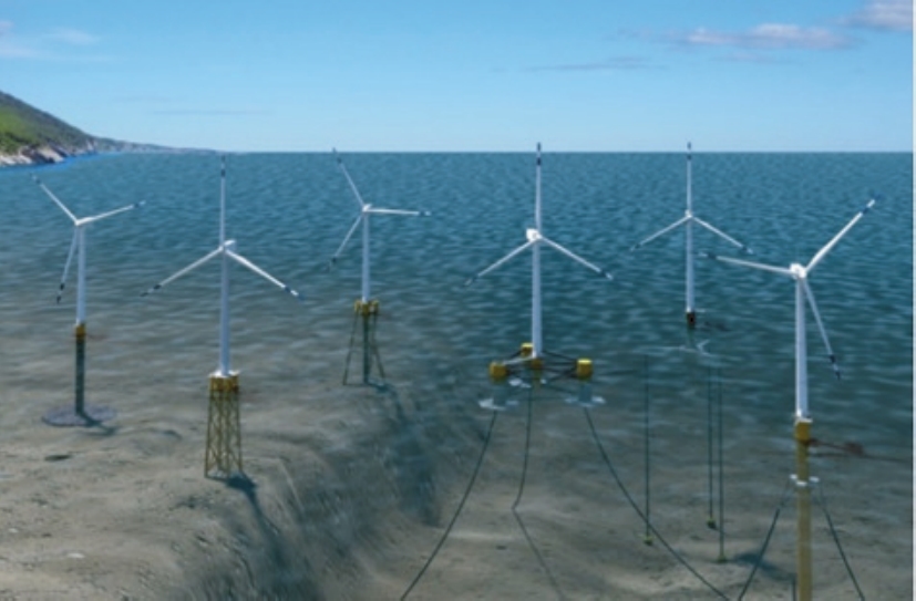
随着近岸优质风场资源逐渐被开发殆尽,海上风电未来将不断走向深远海。在过去,近海浅水风场主要以着床式的固定式风机基础为主,包括单桩、导管架等,这些基础通常需要进行海上桩基施工作业,基础设计频域介于1倍到3倍风轮转子频率之间,随着水深的进一步增加,基础造价和施工成本将急剧上升[2]。相比而言,漂浮式海上风机则属于顺应式柔性结构,通过系泊与海床连接,基础造价和施工安装成本随水深变化的敏感度较传统固定式风机基础低,未来有望通过技术进步和产业链的发展,进一步提高其经济竞争力[3]。漂浮式风机的基础形式借鉴于过往船舶与海洋工程的相关浮体经验,可大致划分为半潜型式,立柱型式,张力腿型式和驳船型式[3],如图1所示。目前,在欧洲和日本已经有部分漂浮式样机和小规模商业化漂浮式风场建设投产[4-6]。ETI预测,漂浮式风机基础技术将在亚洲、美国和欧洲具有广阔的市场空间和发展前景[7]。
然而,相比于传统的海上风机固定式基础,漂浮式风机在风浪环境下,自身运动幅度、速度和加速度都比较大,容易造成风轮入流风速的剧烈变化,湍流度增加,给功率稳定性和结构安全带来较大的挑战。因此,如何以较低的成本有效地提升漂浮式风机基础的运动阻尼,从而优化基础运动特性,是一个重要且现实的研究课题之一。
传统船舶减摇方式,包括减摇鳍、舭龙骨、减摇水舱等,而油气平台则更普遍地采用垂荡板结构。垂荡板是一种简单而有效的浮体水动力性能调节装置,一方面可以通过改变浮体的运动附加质量,从而调节浮体的垂荡固有周期,另一方面则通过垂荡板边缘泄涡而增加系统的垂荡阻尼。漂浮式风机基础作为无动力浮体结构,可参考借鉴油气平台的垂荡板结构,探索垂荡板结构对漂浮式风机的阻尼调节作用。在以往,已有一些研究开始关注垂荡板的水动力特性。Thiagarajan和Troesch[8]通过对裸圆柱体进行水池强迫试验,表明试验柱体底部的圆盘能有效的产生垂荡阻尼,并且阻尼大小与震荡幅度有关。吴维武等人[9]采用计算流体力学软件Fluent对不同形状和开孔率的垂荡板的水动力特性进行了研究,结果表明不同的KC数范围,开孔对垂荡板阻尼的影响不尽相同。目前,一些半潜型漂浮式风机的平台设计也借鉴垂荡板,以优化平台运动性能。Wang等人[10]通过CFD方法对OC4-5 MW半潜型浮式风机的纵摇运动进行了水动力研究,结果表明平台纵摇运动速度最大的时候,垂荡板边缘泄涡产生的阻尼也达到极大值,有效地提升水动力阻尼。
虽然部分研究者已经开始关注到了垂荡板在优化漂浮式风机运动性能的潜力,但是关于垂荡板的设计及漂浮式风机阻尼的改善特性研究仍然不足。因此,本文将针对国内海域普遍适用的半潜型浮式风机开展垂荡板阻尼结构的设计以及阻尼性能的定量化研究,为后续的工程设计提供有益的参考。
HTML
-
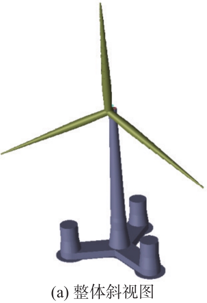
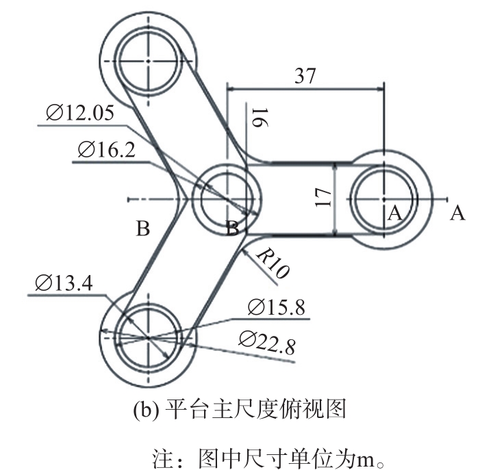
本文采用的漂浮式风机基础为OO-Star漂浮式风机,该浮式风机基础是一个“Y”型浮筒结构,中间设计锥形立柱结构以支撑DTU 10 MW风机,外围设置三个立柱结构,具体结构形式和尺寸如图 2所示。浮式基础的原始设计水深为130 m,吃水为22 m,排水量2.350 9×10⁴ m3。具体结构参数见表1,更多的基础细节可参考文献[11]。

Figure 2. Dimension of the OO-Star floating offshore wind turbines

Figure 2. Dimension of the OO-Star floating offshore wind turbines

Figure 2. Dimension of the OO-Star floating offshore wind turbines
名称 数值 基础质量/kg(不包括塔筒和系泊,含压载) 2.170 9×10⁷ 重心距水面距离/m -15.225 横摇惯性矩/(kg·m2) 9.43×10⁹ 纵摇惯性矩/(kg·m2) 9.43×10⁹ 首摇惯性矩/(kg·m2) 1.63×10¹⁰ 塔柱低端距水面距离/m 11.0 平衡位置吃水(包括系泊系统)/m 22.0 排水量/m3 2.350 9×10⁴ 浮心距水面距离/m 14.236 Table 1.
Basic parameters of the OO-Star floating wind turbines -
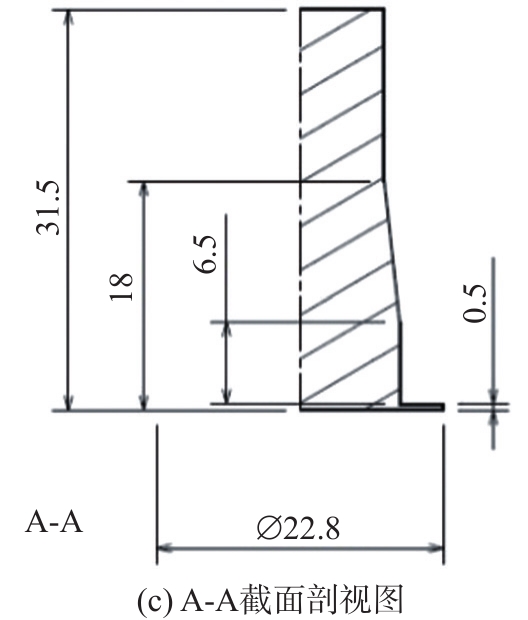
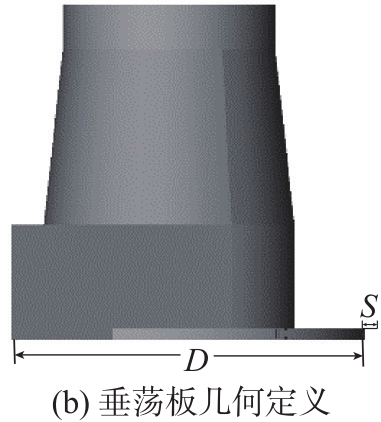
本文在原有垂荡板的基础上,改进垂荡板的结构型式,包括垂荡板外伸尺寸、垂荡板的甲板和底板外伸(本文称为边锋),见图3。

Figure 3. Diagram of the heave-plate structure

Figure 3. Diagram of the heave-plate structure
原模型垂荡板圆盘直径22.8 m,高0.5 m,无边锋延伸。为了研究垂荡板形状参数对浮体水动力阻尼的影响,设置对照模型。模型垂荡板的圆盘直径D分别为22.8 m、23.8 m、24.8 m;边锋延伸部分宽度S分别0.2 m、0.4 m、0.6 m;垂荡板高H分别为0.5 m、0.6 m 、0.7 m,立柱参数不变。计算分析阻尼结构的运动衰减特性。阻尼结构设计方案见表2。
方案 直径D/m 边锋外伸S/m 高H/m 原模型 22.8 0 0.5 模型1 22.8 0.2 0.5 模型2 22.8 0.4 0.5 模型3 22.8 0.6 0.5 模型4 22.8 0.2 0.6 模型5 22.8 0.2 0.7 模型6 23.8 0.2 0.5 模型7 24.8 0.2 0.5 Table 2.
Design schemes of the heave-plate structure -
以垂荡运动为例,给定浮体运动形式为
((1)) 基于自由运动方程:
((2)) 式中:
因此,阻尼系数可表示为:
((3)) 附加质量表示为:
((4)) 由上述过程计算得到风机基础的粘性阻尼(力矩)系数。
-
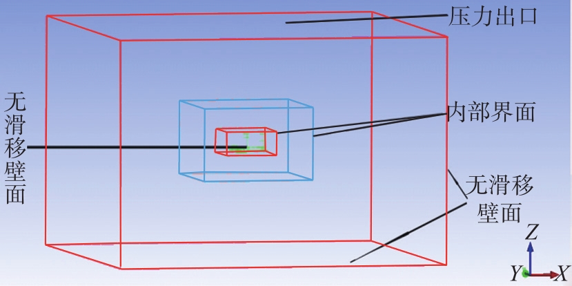
模型的计算域划分及边界条件选取如图4所示。使用ICEM CFD进行网格划分。

Figure 4. Computational region and boundary conditions
由于FLUENT计算时采用动方法,为避免结构物周围网格变形过大,将流场的网格划分为如下三个部分:
1)结构物周围采用刚性网格,计算时随结构物一起运动,该部分选取尺寸较小的四面体网格进行划分。
2)刚性网格外为变形区域,采用尺寸略大的四面体网格进行划分。
3)为节约计算时间,其余区域采用非结构化大尺寸四面体网格,该区域距离物体较远,对结构的受力计算影响较小,且粗网格还可以起到人工阻尼的作用,减少侧壁面反射波影响。
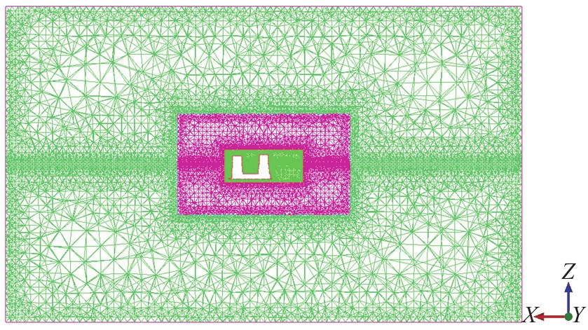
为保证计算精度,每个部分流场网格都在自由液面处对网格进行了加密。选取垂荡板圆盘直径为23.8 m,垂荡板高0.5 m,边锋延伸0.2 m的模型为例,图5为该模型计算域中纵截面的网格示意,图中模型网格总数为422万个。为了说明计算结果的正确性和可靠性,此处进行网格无关性验证,即验证计算结果对于网格密度变化的敏感性。通过改变网格的疏密,观察计算结果的变化,若其变化幅度在允许的范围之内,就可以说明网格误差在可接受精度范围内。因此,对模型重新划分网格,使得网格数量分别为212万个和821万个。

Figure 5. Section mesh of the computational region
各个网格模型的计算附加质量和阻尼系数结果如表3所示,计算结果对于网格密度变化的敏感性很小,网格无关性得以验证。
网格数/万个 附加质量 阻尼系数/(N·s·m-1) 无因次阻尼系数 变化率/% 212 10 236 877 975 2 249 987 262 0.114 4 -2.54 422 10 036 272 256 2 285 078 900 0.117 4 0 821 10 148 250 016 2 268 521 399 0.115 9 -1.29 Table 3.
Results with different mesh quantities -
将发电工况下波浪的谱峰周期作为浮体强迫运动的周期,选取风机基础垂荡和横摇运动响应的有义值,由此规定简谐强迫运动形式如表4所示。
运动形式 发电工况 周期/s 幅值/m 垂荡 7.5 1.75 横摇 7.5 1.29 Table 4.
Parameters in test cases 将划分好的网格文件导入FLUENT商业软件,把上述强迫运动编写为用户自定义函数(UDF文件)来定义物体的简谐运动,定义简谐运动周期T=7.5 s,垂荡运动幅值A=1.75 m,横摇运动A=1.29°。计算采用Standard k-ε湍流模型,以及PISO求解格式。
1.1 平台基础结构
1.2 阻尼结构设计
1.3 数值模型
1.3.1 粘性阻尼力(矩)系数计算方法


1.3.2 计算域与网格设置
1.3.3 计算域与网格设置
-
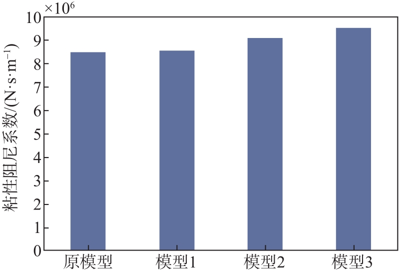
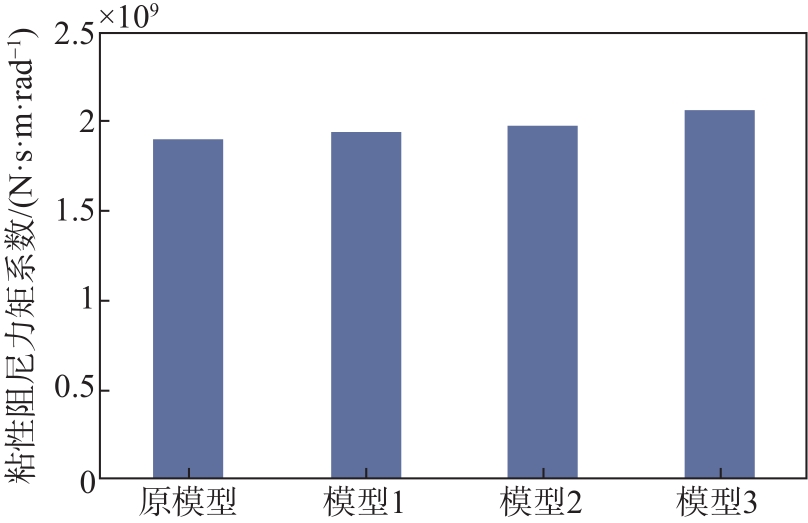
为了研究垂荡板边锋延伸宽度变化对浮式风机水动力阻尼系数的影响,将原模型及模型方案1、2、3的计算结果进行对比分析。各模型无因次阻尼系数计算结果见表5,边锋外伸量S变化时风机基础垂荡阻尼的变化趋势见图6,风机基础横摇阻尼的变化趋势见图7。
模型及运动 无因次垂荡阻尼系数 增长率/% 无因次横摇阻尼系数 增长率/% 原模型 0.175 3 0 0.103 3 0 模型1(延伸0.2 m) 0.176 5 0.68 0.106 3 2.95 模型2(延伸0.4 m) 0.183 7 4.79 0.106 0 2.61 模型3(延伸0.6m) 0.192 3 9.70 0.110 4 6.90 Table 5.
Damping impact from the wing extension 
Figure 6. Damping variation of heave motion from the wing extension of heave-plate

Figure 7. Damping variation of roll motion from the wing extension of heave-plate
由图表数据可知,随着边锋外伸S的增大,基础垂荡粘性阻尼系数随之增大。由此可得,在一定范围内增大S,能增加垂荡板垂荡阻尼性能。当垂荡板边锋延伸S为0.6 m时,垂荡粘性阻尼系数增大近10%,阻尼性能增加效果较为明显。
从图表数据来看,随着S的增大,基础横摇粘性阻尼系数总体也呈增大趋势。由此可得,在一定范围内增大S,能增加垂荡板横摇阻尼性能。但是相比于垂荡运动方向的阻尼变化值,横摇运动方向的增阻效果并不十分明显。
-
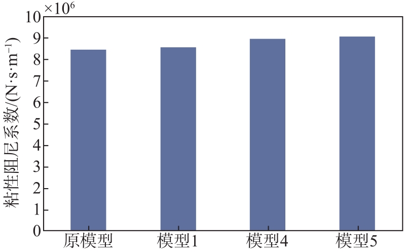
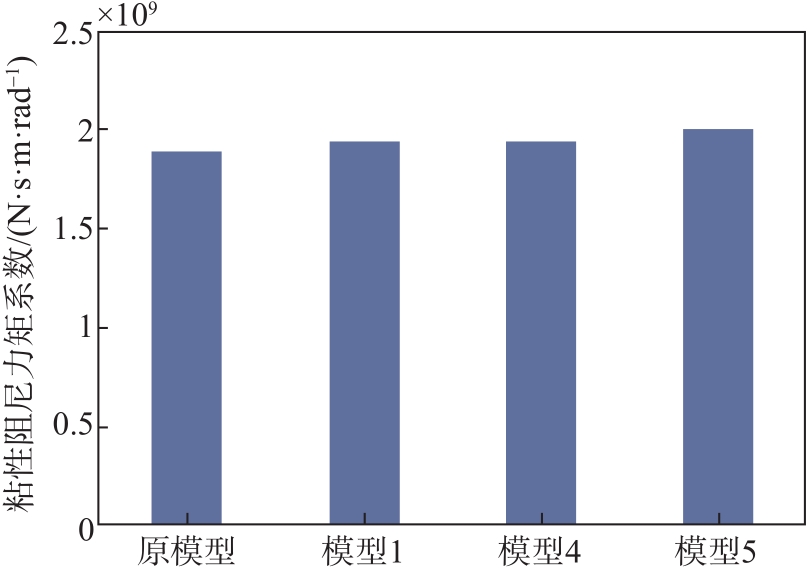
为了研究垂荡板高度变化对浮式风机基础平台运动阻尼系数的影响,把原模型及模型方案1、4、5的计算结果进行分析。各模型无因次阻尼系数计算结果见表6,垂荡板高度H变化时风机基础垂荡阻尼的变化趋势见图8,基础横摇阻尼的变化趋势见图9。
模型及运动 无因次垂荡阻尼系数 增长率/% 无因次横摇阻尼系数 增长率/% 原模型(高0.5 m) 0.175 3 0 0.103 3 0 模型1(高0.5 m) 0.176 5 0.68 0.106 3 2.90 模型4(高0.6 m) 0.179 9 2.62 0.104 3 0.93 模型5(高0.7 m) 0.187 6 7.01 0.107 7 4.26 Table 6.
Damping impact from height of heave-plate 
Figure 8. Damping variation of heave motion from the height of heave-plate

Figure 9. Damping variation of roll motion from the height of heave-plate
由图表数据可知,随着垂荡板高度H的增大,基础垂荡方向的水动力粘性阻尼系数随之增大。由此可得,在一定范围内增大垂荡板高度,能增加垂荡板的垂荡阻尼性能。当垂荡板高度为0.7 m时,阻尼增大7%。
从图表数据来看,随着垂荡板高度H的增大,粘性阻尼系数总体呈增大趋势。由此可得,在一定范围内增大垂荡板高度,能增加垂荡板横摇阻尼性能,但增长效果小于5%。
-
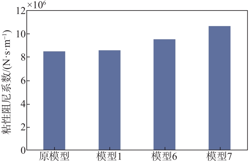
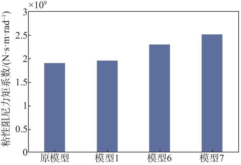
为了研究垂荡板圆盘直径变化对垂荡阻尼系数的影响,把原模型及模型方案1、6、7的计算结果进行分析。各模型无因次阻尼系数计算结果见表7,圆盘直径D变化时风机基础垂荡阻尼的变化趋势见图10。基础横摇阻尼的变化趋势见图11。
模型及运动 无因次垂荡阻尼系数 增长率/% 无因次横摇阻尼系数 增长率/% 原模型(直径22.8 m) 0.175 3 0 0.103 3 0 模型1(直径22.8 m) 0.176 5 0.68 0.106 4 3.00 模型6(直径23.8 m) 0.184 7 5.36 0.117 4 13.64 模型7(直径24.8 m) 0.201 8 15.12 0.121 2 17.32 Table 7.
Damping impact from the diameter of heave-plate 
Figure 10. Damping variation of heave motion from the diameter of heave-plate

Figure 11. Damping variation of roll motion from the diameter of heave-plate
从图表数据来看,随着圆盘直径D的增大,浮式基础垂荡运动的粘性阻尼系数随之增大。由此可得,在一定范围内增大圆盘直径,能增加垂荡板的垂荡阻尼性能,并且随着圆盘直径增加呈非线性增长趋势,增阻效果明显,圆盘直径增加2 m(相比于原模型增加8.77%)时,垂荡阻尼增加可达15.12%。
从图表数据来看,随着圆盘直径D的增大,浮式基础横摇运动的粘性阻尼系数增大。由此可得,在测试范围内增大圆盘直径,能增加垂荡板的横摇阻尼性能。圆盘直径增加2 m(相比于原模型增加8.77%)时,基础横摇方向的运动阻尼增加值可达17.32%,增阻效果较为显著。
对比前述的结果,相对其他参数而言,增加垂荡板直径D,垂荡板阻尼增长效果最为显著,其次是增加边锋延伸长度,而增加垂荡板高度所带来的基础运动阻尼增加值十分有限。
-
根据之前模型计算结果分析,调整垂荡板的尺寸,进一步提高垂荡板的阻尼性能。调整优化后垂荡板的尺寸为:直径24.8 m、高0.7 m、边锋延伸0.6 m的垂荡板。按照调整后垂荡板的尺寸,计算浮式基础的垂荡及横摇阻尼性能。将计算结果与原模型进行对比,可以看出优化后阻尼性能得到了理想的提升,具体阻尼系数增长情况如表8所示。优化后,该浮式风机平台的阻尼提升25%以上。
模型及运动 无因次阻尼系数 阻尼系数增长率/% 有量纲 无量纲 原模型(高0.5 m) 0.175 3 — — 模型1(高0.5 m) 0.201 4 26.175 14.9 模型4(高0.6 m) 0.103 3 — — 模型5(高0.7 m) 0.123 0 28.455 19.1 Table 8.
Damping comparison between the original model and optimized model -
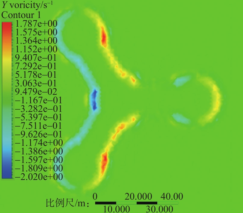
相关研究表明[12],阻尼产生的根本原因是结构运动泄涡时对动能的耗散。对于风机基础结构来说,其在运动过程中产生、脱落的漩涡越多,能量耗散越大,阻尼性能也就越好。
如图12中,红色部分表示较大的正漩涡,黄色部分表示较小的正漩涡,深蓝色部分表示较大的负漩涡,浅蓝色部分表示较小的负漩涡。随着外伸边锋的增大,运动产生漩涡的范围会扩大,产生的漩涡量会增多,从而耗散更多能量,使得模型结构阻尼增加。

Figure 12. Vorticity contours of the foundation of the floating offshore wind turbine in heave
2.1 边锋延伸宽度
2.2 垂荡板高度
2.3 垂荡板圆盘直径
2.4 总体影响对比
2.5 泄涡分析
-
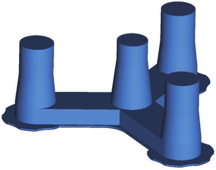
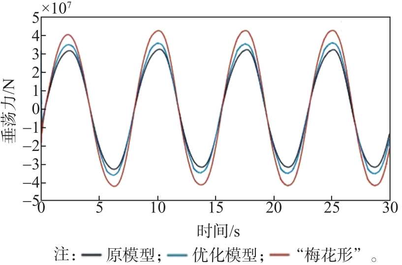
根据上述阻尼结构尺寸敏感性分析和泄涡原理分析,为了得到阻尼性能更好的垂荡板形式,设计了一种“梅花形”的垂荡板。该垂荡板模型从优化后的模型变形而来,边锋宽度、板高及圆盘直径各参数都保持不变,在减小垂荡板圆盘面积的同时增加了垂荡板圆盘的周长。网格划分方法与之前模型相同,均采用“体网格+面网格”的方式。模型网格总数为459万个。垂荡板整体模型见图13所示,模型强迫运动时历曲线见图14所示,阻尼性能计算结果对比见表9。

Figure 13. Schematic diagram of the whole model of cinquofoil

Figure 14. Schematic diagram of the whole model of cinquefoil
模型及运动 无因次阻尼系数 阻尼系数增长率/% 原模型垂荡 0.175 3 — 优化后模型垂荡 0.201 4 14.90 “梅花形”垂荡 0.204 5 36.98 Table 9.
Calculation results of damping performance of "quincunx-shaped" heave-plate 在其他参数不变的情况下,“梅花形”垂荡板垂荡运动阻尼性能最佳,其垂荡阻尼系数较原始模型提升36.98%。
-
本文选取10 MW半潜型浮式风机,利用计算流体力学的方法研究外立柱垂荡板结构几何尺寸变化对基础运动粘性阻尼的影响。数值计算结果表明,本文优化参数后的垂荡板能够明显地增加基础的附加质量与附加转动惯量,增加结构的阻尼,耗散运动能量,改善结构运动性能;带边锋的垂荡板的阻尼性能与圆盘直径、边锋延伸宽度、垂荡板高等参数均有关。一般来说,在一定范围内增大圆盘直径、边锋延伸宽度、垂荡板高,均会增加系统的附加质量和垂荡、横摇粘性阻尼系数。
从总体情况来看,对阻尼性能影响最大的因素是垂荡板圆盘直径,尤其是对于横摇运动来说阻尼效果更明显。其次,增加边锋延伸宽度对增加垂荡阻尼性能也比较有利,而加大垂荡板的高度也可增大阻尼,但是增加缓慢。因此,增大阻尼三种措施按照有效性排序为:直径加大、边锋延伸、高度加大。本文优化方案中,直径24.8 m、高0.7 m、边锋延伸0.6 m的阻尼结构,该阻尼结构无量纲阻尼系数为:垂荡阻尼系数为20.14%,较原结构增大无量纲阻尼系数14.9%;摇摆阻尼系数12.30%,较原结构增大无量纲阻尼系数19.1%。本文设计的“梅花型”垂荡板结构相比原阻尼结构有效提升36.98%的垂荡阻尼。
但是,在实际的设计过程中,垂荡板的设计尺寸和形式需要进一步结合考虑结构的强度、施工运输可行性以及经济性。

 DownLoad: