• Peer Review
  • Non-profit
  • Global Open Access
  • Green Channel for Rising Stars
Volume 8 Issue 3
Sep.  2021
Turn off MathJax
Article Contents

REN Hao,FANG Hui,WEI Xinze.Structural Finite Element Simulation and Evaluation Method for Ship Collision Damage and Residual Strength of the Jacket[J].Southern Energy Construction,2021,08(03):26-33. doi:  10.16516/j.gedi.issn2095-8676.2021.03.004
Citation: REN Hao,FANG Hui,WEI Xinze.Structural Finite Element Simulation and Evaluation Method for Ship Collision Damage and Residual Strength of the Jacket[J].Southern Energy Construction,2021,08(03):26-33. doi:  10.16516/j.gedi.issn2095-8676.2021.03.004

Structural Finite Element Simulation and Evaluation Method for Ship Collision Damage and Residual Strength of the Jacket

doi: 10.16516/j.gedi.issn2095-8676.2021.03.004
  • Received Date: 2021-06-11
  • Rev Recd Date: 2021-08-13
  • Publish Date: 2021-09-25
  •   Introduction  The vessel collision of jacket foundation in an offshore wind farm in the South China Sea happens frequently. Under this circumstance, the accurate assessment of the residual strength after structural damage has become an important technology of the safety of wind farm operation and maintenance.  Method  Based on the actual jacket structure of a wind farm in the South China Sea and considering the actual ship operation situation in the sea area, this paper used the finite element software ABAQUS to simulate the ship collision damage process of jacket foundation under different combinations of ship mass, initial velocity and collision angle.  Result  By using the quasi static method, the time interval of the collision forces and the plastic strain contours of the key nodes under different working conditions are concluded. Besides, the relationship between the maximum impact forces and impact factors and typical characteristics of the damage are concluded.  Conclusion  Based on the analysis, the typical change laws of the residual strength after the ship collision of the jacket are concluded to provide technological support for rapid assessment of the collision damage of related structures in the actual engineering process.
  • [1] 李艳贞. 船舶与海上风电站碰撞的数值仿真研究 [D]. 上海:上海交通大学,2010.

    LIY Z. Numerical simulation study of offshore wind turbine sricken by ship [D]. Shanghai:Shanghai Jiao Tong University,2010.
    [2] 郝二通. 海上风电机组结构抗船撞及抗震性能研究 [D]. 大连:大连理工大学,2016.

    HAOE T. Structural performance studies on offshore wind turbine subjected to ship impacts and earthquakes [D]. Dalian:Dalian University of Technology,2016.
    [3] MINORSKYV U. An analysis of ship collision with reference to protection of nuclear power ships [J]. Journal of Ship Research,1959,3(2):208-214.
    [4] TABRIK,VARSTAP,MATUSIAKJ. Numerical and experimental motion simulations of nonsymmetric ship collisions [J]. Journal of Marine Science and Technology,2010,15(1):87-101.
    [5] 唐友刚,朱龙欢,李焱,等. 南海某导管架海洋平台倒塌分析 [J]. 海洋工程,2016,34(2):105-110.

    TANGY G,ZHUL H,LIY,et al. Pushover analysis on a jacket offshore platform in the South China Sea [J]. The Ocean Engineering,2016,34(2):105-110.
    [6] 王巍巍,周雷,张传杰,等. 基于SACS倒塌分析的导管架平台极限承载力分析 [J]. 广州化工,2017,45(6):142-144+147.

    WANGW W,ZHOUL,ZHANGC J,et al. Study on ultimate bearing capacity calculation of jacket platform from SACS collapse analysis [J]. Guangzhou Chemical Industry,2017,45(6):142-144+147.
    [7] LIR X,YANAGIHARAD,YOSHIKAWAT. Axial compressive residual ultimate strength of circular tube after lateral collision [J]. International Journal of Naval Architecture and Ocean Engineering,2018,11(1):396-408.
    [8] DNV GL AS. Offshore standard safety principles and arrangements:DNVGL-OS-A101 [S]. Norway:DNV GL AS,2015.
    [9] DNV GL AS . Determination of structural capacity by non-linear finite element analysis methods: DNVGL-RP-C208 [S]. Norway:DNV GL AS,2016.
    [10] 同济大学土木工程防灾国家重点实验室. 南京长江第四大桥船舶撞击动力分析研究 [R]. 上海:同济大学,2007.

    State Key Laboratory of Disaster Prevention in Civil Engineering,Tongji University. Dynamic analysis of ship collision on the Fourth Nanjing Yangtze River Bridge [R]. Shanghai:Tongji University,2007.
    [11] American Association of State Highway and Transportation Officials. Guide Specification and Commentary for Vessel Collision Design of Highway Bridges:AASHTO GVCB AMD-2009 [S]. Washington:AASHTO,2009.
    [12] VROUWENVELDERA. Design for ship impact according to Eurocode1,Part2.7 [M]. London: Routledge,1998.
  • 通讯作者: 陈斌, bchen63@163.com
    • 1. 

      沈阳化工大学材料科学与工程学院 沈阳 110142

    1. 本站搜索
    2. 百度学术搜索
    3. 万方数据库搜索
    4. CNKI搜索

Figures(21)  / Tables(6)

Article Metrics

Article views(442) PDF downloads(62) Cited by()

Related

Structural Finite Element Simulation and Evaluation Method for Ship Collision Damage and Residual Strength of the Jacket

doi: 10.16516/j.gedi.issn2095-8676.2021.03.004

Abstract:   Introduction  The vessel collision of jacket foundation in an offshore wind farm in the South China Sea happens frequently. Under this circumstance, the accurate assessment of the residual strength after structural damage has become an important technology of the safety of wind farm operation and maintenance.  Method  Based on the actual jacket structure of a wind farm in the South China Sea and considering the actual ship operation situation in the sea area, this paper used the finite element software ABAQUS to simulate the ship collision damage process of jacket foundation under different combinations of ship mass, initial velocity and collision angle.  Result  By using the quasi static method, the time interval of the collision forces and the plastic strain contours of the key nodes under different working conditions are concluded. Besides, the relationship between the maximum impact forces and impact factors and typical characteristics of the damage are concluded.  Conclusion  Based on the analysis, the typical change laws of the residual strength after the ship collision of the jacket are concluded to provide technological support for rapid assessment of the collision damage of related structures in the actual engineering process.

REN Hao,FANG Hui,WEI Xinze.Structural Finite Element Simulation and Evaluation Method for Ship Collision Damage and Residual Strength of the Jacket[J].Southern Energy Construction,2021,08(03):26-33. doi:  10.16516/j.gedi.issn2095-8676.2021.03.004
Citation: REN Hao,FANG Hui,WEI Xinze.Structural Finite Element Simulation and Evaluation Method for Ship Collision Damage and Residual Strength of the Jacket[J].Southern Energy Construction,2021,08(03):26-33. doi:  10.16516/j.gedi.issn2095-8676.2021.03.004
  • 近年来,我国海上风电事业大力发展,但是在风电装备运行过程中,船舶失控撞击风电基础结构的事故频发,轻则导致结构局部凹陷,重则导致结构整体变形,严重影响结构的承载性能。2017年8月20日,台风“天鸽”侵袭南海附近海域,将大量船只卷入海上风电场,造成风电基础设施严重损伤。目前,我国对海上风电基础结构船撞事故研究较少,针对海洋结构物碰撞的计算分析方法与规范不足,无法实施损伤结构的承载性能评估,导致后续工程的施工及运行维护无法进行,只得拆除损伤结构,造成大量的经济损失。因此,结构损伤与剩余强度评估成为海上风电场运维保障关键技术之一。本文以某海上风电场项目为依托,开展船撞事故后导管架结构损伤与剩余强度研究。

    海上风电结构体积较大,4 MW风机导管架基础泥面以上高度约18 m,针对其碰撞问题的研究,采用现场试验或比例模型试验的成本较高,多采用理论或数值方法进行分析。李艳贞1基于5 000 t船舶和桁架式导管架基础海上风机,采用非线性有限元动态响应分析程序MAC.Dytran以不同碰撞速度对导管架基础进行碰撞研究,得到结构局部损伤特性、碰撞力-凹陷位移曲线和能量转化形式特点。其次研究了一集装箱船船侧正碰导管架风电基础,同时获得了两者损伤情况,比较了两者的各自能量吸收。其评估方法主要从能量转化来研究撞深曲线的变化特征,并未使用局部评估准则和进行其他工况下的模拟。郝二通2利用有限元软件LS-DYNA进行船舶与单桩基础碰撞研究,从能量转化、最大碰撞力、基础损伤状态和风机动力响应等问题进行了探讨。首先介绍了碰撞能量转化形式,进而研究不同吨位、不同速度、不同角度对碰撞结果的影响,得出相应的结论。其次使用面积受损率来反映单桩基础的受损程度并应用计算受损区域和受损面积。Minorsky3于1959年提出了米诺斯基关系曲线,根据能量守恒原理,给出钢材体积变形与碰撞冲击能之间的关系。Tabri等4将船舶运动方程对时间进行积分,提出一种用于模拟非对称船舶碰撞的计算模型,建立了碰撞力与碰撞位置、碰撞角度之间的关系。

    针对结构损伤及剩余强度的研究,多采用有限元方法进行数值模拟分析。唐友刚等5采用非线性有限元方法,考虑平台环境荷载及桩土作用,采用逐步加载的方式,演示了南海某导管架结构的失效倒塌过程,计算了结构的极限强度。王巍巍等6采用SACS有限元分析软件中的倒塌分析模块,计算了导管架平台的极限承载力,提出了该模块下基本分析参数的设定方法。Li等7利用非线性有限元分析软件LS-DYNA,研究了损伤圆管剩余极限强度与侧向冲击能量耗散之间的关系,分析了管长、管径、管壁厚度及冲击能等参数对极限强度的影响。

    本文以南海某海上风电场的导管架基础结构为例,建立有限元数值模型,考虑该海域船舶运行的实际情况,数值模拟船舶质量、初速度、碰撞角度等不同组合情况下,导管架基础的船撞损伤过程,阐明最大碰撞力与各撞击因素之间的关联关系,评估导管架船撞后的剩余强度。本文研究可以为实际工程中快速评估相关结构的船撞损伤提供技术支撑和参考依据。

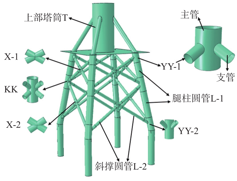
  • 本研究采用单机容量为4 MW的南海某海上风电导管架基础结构,导管架有限元模型见图1,导管架整体各段的几何参数在表1中列出。

    Figure 1.  Finite element model diagram of the jacket

    名称长度直径厚度
    位置主管支管主管支管主管支管
    YY-12 3231 0292 7008005526
    KK3 2501 0291 4586345526
    X1 9701 9706346342614
    YY-23 0001 0291 4586345526
    L-11 40026
    L-263414
    T10 8299 6384 5001 5005526

    Table 1.  Statistical table of the size of each part of the jacket

    根据挪威船级社规范(DNVGL-OS-A101)规定8,采用典型船只计算碰撞能量时,船艏撞击动能不得小于11 MJ,船舶碰撞能量计算公式如下:

    E=12(M+m)v2 ((1))

    式中:M是船舶满载质量(t);m是船舶附加质量(t);v是碰撞速度(m/s)。对于单机容量6 MW的风电基础结构,结合南海海域过往船只情况,并考虑实际结构产生的凹陷损伤,在分析船体结构弹塑性材料和结构内部分布特征的基础上,选用一艘满载质量为3 000 t的散货船,该散货船的具体尺寸见表2

    总长型宽型深空载吃水满载吃水
    8113.66.92.65.6

    Table 2.  
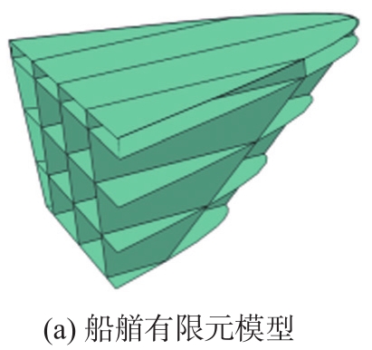
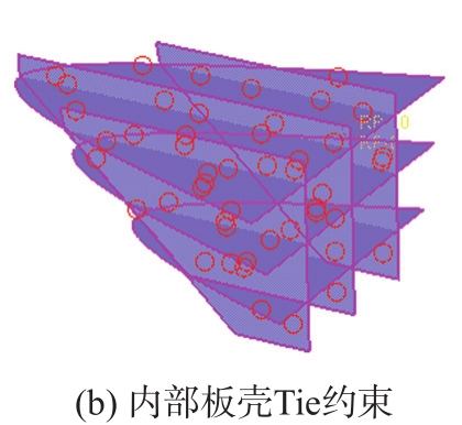
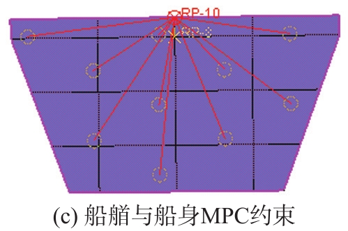
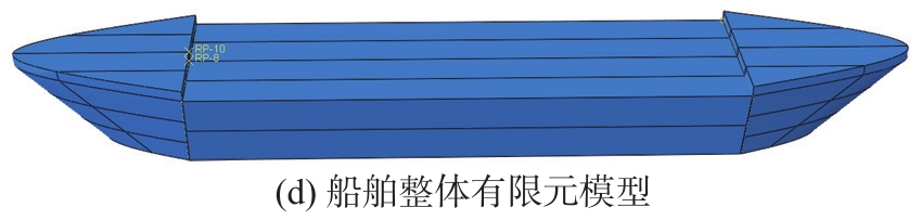
Statistical table of ship dimensions

    在工程领域常见的船舶碰撞问题中,碰撞损伤部位多为船艏,为提高计算效率,简化船体模型,采用飞剪型船艏型式,单元类型为壳单元(S4R和S3R),如图2(a)所示,采用Tie约束连接内部板壳结构,如图2(b)所示。设置船身与船尾为刚体,采用MPC约束与船艏截面连接,如图2(c)所示。船舶整体结构有限元模型如图2(d)所示。

    Figure 2.  FEM model of the ship structure

    Figure 2.  FEM model of the ship structure

    Figure 2.  FEM model of the ship structure

    Figure 2.  FEM model of the ship structure

    材料本构关系采用DNVGL-RP-C2089规范中推荐的弹塑性硬化模型,具有线弹性和屈服平台的幂次硬化模型参数。材料屈服满足下式:

    f=σeq-σfεp=0 ((2))

    式中:σeq为材料的Mises等效应力(Pa);σf为材料的等效应力(Pa)。材料硬化满足Hollmon幂次硬化准则,应力应变关系为:

    σfεp=σyield2                  if εpεp,y2K[εp+σyield2K-εp,y2]n  if εp>εp,y2 ((3))

    式中:εp为材料的等效应变;σyield2为硬化开始时的应力;εp,y2为硬化开始时的等效塑性应变;Kn为硬化系数,n取值为0.166。根据海上风电场工程的实际情况,导管架结构采用低碳钢S355,船舶材料采用S235,具体的材料参数见表3表4

    σprop/MPaσyield1/MPaσyield2/MPaεp,y1εp,y2K/MPa
    384.0428.4439.30.0040.015900

    Table 3.  Proposed average parameters of steel properties in the mild steel S355 specification

    σprop/MPaσyield1/MPaσyield2/MPaεp,y1εp,y2K/MPa
    285.8318.9328.60.0040.02700

    Table 4.  Proposed average parameters of steel properties in the mild steel S255 specification

  • 船舶在水中的实际航行过程中,其运动特性主要表现为横荡与纵荡,其中:船舶纵荡对撞击影响较大。为提高计算效率,在模拟船舶撞击导管架结构时,将水对船体的作用简化为附连水的质量,综合各项标准,取含附连水船舶质量为设计船体满载质量的1.05倍8。根据公路桥涵设计手册,摩擦系数取0.210,接触为硬接触,导管架采用底部固支约束。数值模拟采用显式有限元分析软件ABAQUS/Explicit,碰撞部位选择KK节点(见图1),设置船舶质量、撞击速度和碰撞角度不同组合的工况,如表5所示。

    编号船舶质量/t撞击速度/(m·s-1碰撞角度/(°)
    1500390
    2500490
    31 000290
    41 000390
    51 000490
    61 000590
    72 000290
    82 000390
    92 000490
    102 000590
    113 000390
    123 000490
    131 000350
    141 000370
    152 000350
    162 000370

    Table 5.  Statistical table of calculation conditions

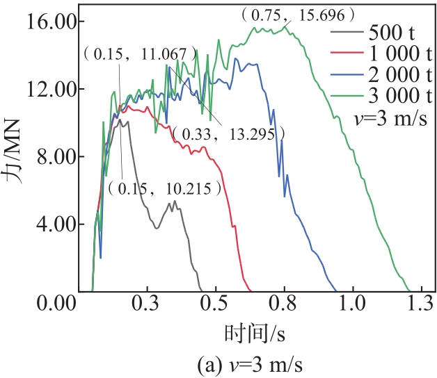
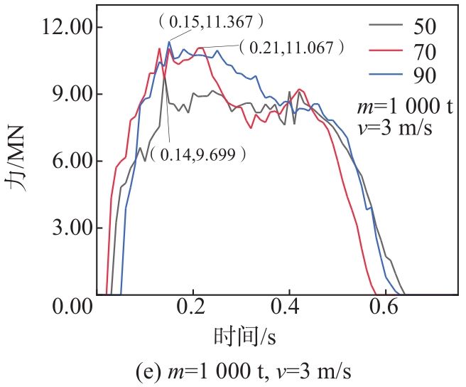
  • 导管架遭受船舶撞击后,整体结构发生形变,撞击局部出现不同程度的凹陷,某些薄弱部位甚至会发生断裂。在各国关于碰撞问题的规范中,常以碰撞力的方式量化碰撞过程,本文在各国碰撞力经验公式的基础上,依据南海某风电场导管架遭受碰撞的实际情况,提取不同组合工况下的碰撞力,如图3所示。

    Figure 3.  Curves of collision forces under different combined working conditions

    Figure 3.  Curves of collision forces under different combined working conditions

    Figure 3.  Curves of collision forces under different combined working conditions

    Figure 3.  Curves of collision forces under different combined working conditions

    Figure 3.  Curves of collision forces under different combined working conditions

    Figure 3.  Curves of collision forces under different combined working conditions

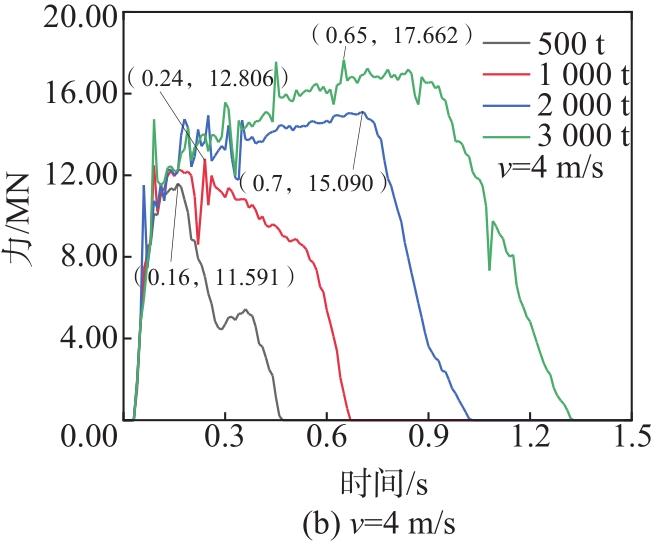
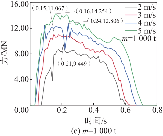
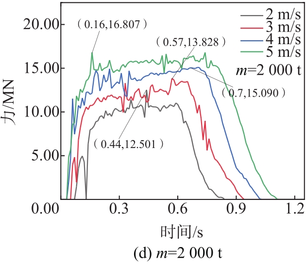
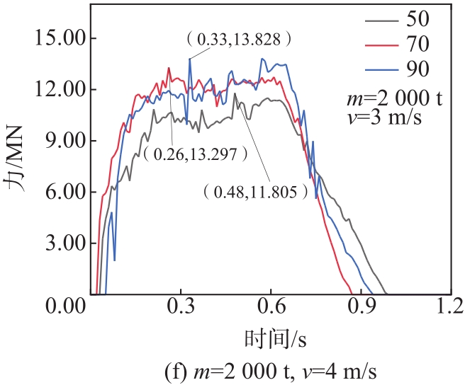
    图3(a)和(b)分别给出撞击速度为3 m/s和4 m/s时不同质量船舶碰撞力的曲线图,可以看出:碰撞时间随船舶质量增大而增大,最大碰撞力出现的时间点无明显规律。图3(c)和(d)分别给出船舶质量为1 000 t和2 000 t时不同撞击速度的碰撞力曲线图,由图可知,碰撞时间随撞击速度增大而增大,并且船舶质量越大,曲线波动越快,表现为导管架结构震荡频率越高。图3(e)和(f)分别是相同撞击速度下质量为1 000 t和2 000 t的船舶以不同角度撞击KK节点的碰撞力曲线图,发现船舶碰撞时间与碰撞角度无明显相关关系,同样碰撞角度下,2 000 t船舶碰撞的撞击力曲线波动更快。

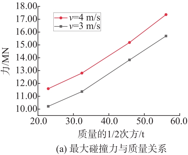
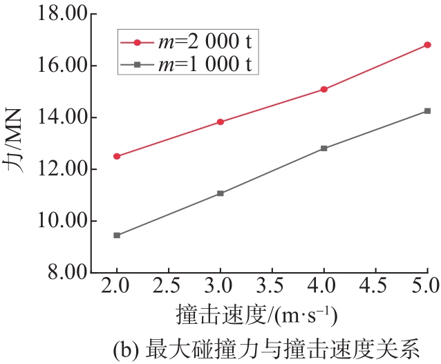
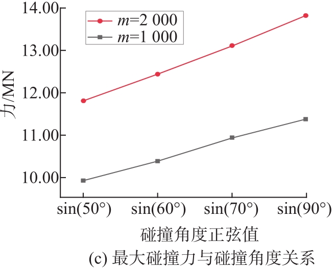
    图4(a)、(b)和(c)分别给出最大碰撞力与船舶质量、撞击速度和碰撞角度的关系曲线图,由图4(a)和(b)可知,最大碰撞力分别与质量的1/2次方和撞击速度均呈线性正相关关系,与AASHTO规范公式11和欧洲规范公式12中关于最大碰撞力与质量和撞击速度的关系变化趋势一致。从图4(c)可以看出,最大碰撞力与碰撞角度正弦值也呈线性正相关关系。

    Figure 4.  Curves of collision forces under different variables

    Figure 4.  Curves of collision forces under different variables

    Figure 4.  Curves of collision forces under different variables

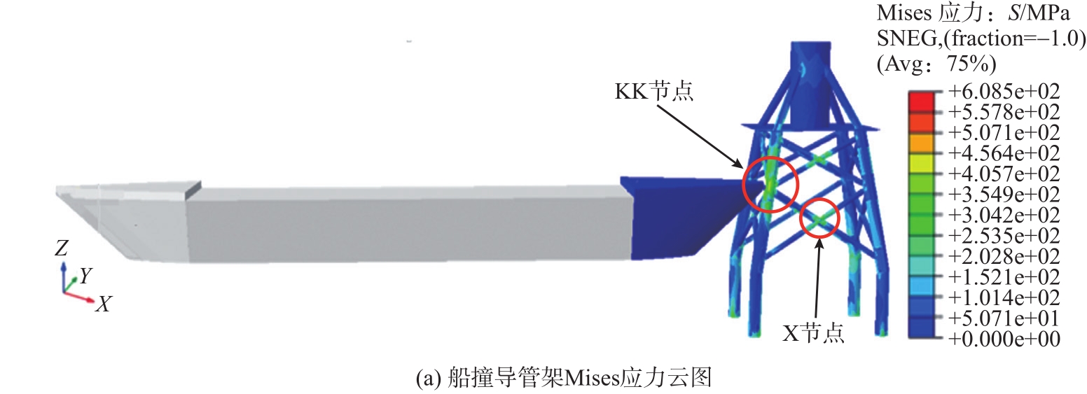
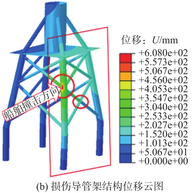
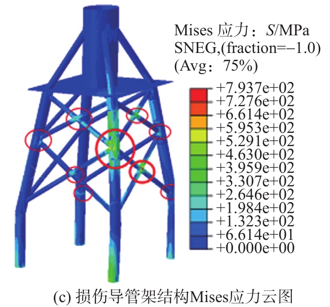
  • 图5(a)给出导管架遭受到船舶撞击后的Mises云图,可以看出,最先变形部位出现在与船舶直接接触的局部,即受撞击的KK节点。从图5(b)可以看出,节点处出现明显的凹陷,与此同时,沿撞击方向导管架侧面桁架受挤压作用,变形效果比其他侧面更为显著。从图5(c)可以看出,损伤导管架应力较大的部位主要集中在受碰撞的管面周围,同时其他各节点均出现不同程度的应力集中现象。应力集中主要发生在管节点接缝处,其中:沿撞击方向导管架侧面桁架下部X节点应力变形较大,是影响整体极限承载力的关键部位。

    Figure 5.  Response of jacket structure after ship collision

    Figure 5.  Response of jacket structure after ship collision

    Figure 5.  Response of jacket structure after ship collision

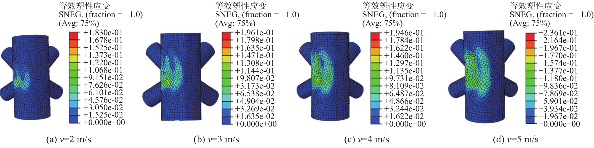
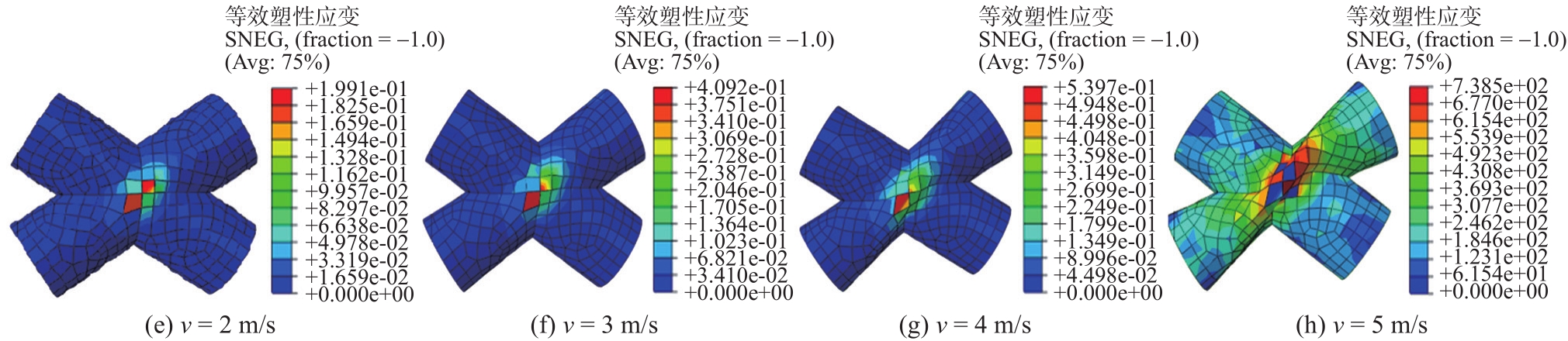
    以质量为1 000 t的船舶为例,图6给出不同撞击速度下受撞击KK节点以及导管架变形最大侧面下部X节点的等效塑性应变云图。

    Figure 6.  Equivalent plastic strain nephogram of KK node and X node of the jacket under different impact velocities

    Figure 6.  Equivalent plastic strain nephogram of KK node and X node of the jacket under different impact velocities

    图6(a)~图6(d)分别表示不同撞击速度下遭受撞击KK节点的等效塑性应变云图,图6(e)~图6(h)分别表示不同撞击速度下变形最严重X节点的等效塑性应变云图。由KK节点等效塑性应力云图可知,撞击速度越大,局部塑性应变越大,凹陷面积越大,凹坑越深。由X节点等效塑性应变云图可知,船舶撞击速度越大,该节点挤压作用越明显,当速度达到4 m/s时,该节点处出现单元失效,实际工况中表现为节点断裂。

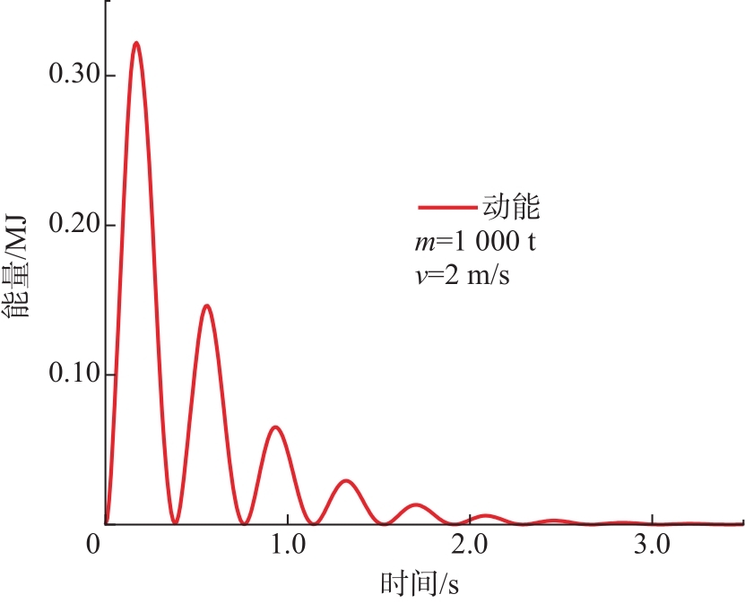
  • 导管架遭受船舶撞击时,结构整体发生弹性变形,船舶与结构分离后,导管架弹性势能转化为动能,由于存在结构阻尼,导管架运动表现为前后衰减震荡。在有限元计算中,为提高计算效率,通过施加阻尼器的形式实现导管架动能衰减,达到自然稳定状态,分析结果见图7

    Figure 7.  Energy attenuation curve of jacket damage structure

    选择不同组合工况下动态衰减后的损伤应力状态,导入下一步分析中,采用准静态方法求解损伤结构的剩余强度。准静态方法需要应用结构的非线性运动方程求解,计算公式如下:

    Mu¨=P-{I} ((4))

    式中:M为质量矩阵;u¨为加速度矩阵;P为荷载矩阵;{I}为内力矩阵。图8给出拟合极限强度曲线,曲线图的横纵坐标比例为22.5 MN/m,当曲线图相邻两点连线与力轴夹角达到70°时,认为该点强度值为结构极限强度。

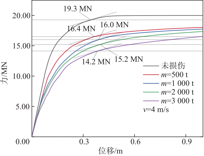
    Figure 8.  Remaining strength curve of jacket when ships of different masses impact at 4 m/s

    表6可知,相同撞击速度下,导管架剩余强度随船舶质量的增大而降低;相同船舶质量下,导管架剩余强度随撞击速度增大而降低;相同初始动能下,船舶质量和速度组合工况不同时,导管架剩余强度存在较小的差距。当船舶动能相同,碰撞角度分别为50°、60°和70°时。损伤导管架的剩余强度基本一致;与正向撞击相比,导管架剩余强度在非正向撞击情况下降幅较大。

    工况设置船舶动能(含附连水质量)/MJ极限(剩余)承载力/MN降幅/%
    未损伤19.3
    v=3 m/sm=500 t2.3616.713.47
    m=1 000 t4.7316.315.54
    m=2 000 t9.4516.116.58
    m=3 000 t14.1815.619.17
    v=4 m/sm=500 t4.216.415.03
    m=1 000 t8.416.017.1
    m=2 000 t16.815.221.24
    m=3 000 t25.214.226.42
    m=1 000 tv=2 m/s2.117.011.92
    v=3 m/s4.7316.415.03
    v=4 m/s8.416.116.58
    v=5 m/s13.1315.818.13
    m=2 000 tv=2 m/s8.416.514.51
    v=3 m/s9.4516.315.54
    v=4 m/s16.815.221.24
    v=5 m/s26.2513.729.02
    m=1 000 tv=3 m/sα=50°4.7316.216.06
    α=60°4.7316.216.06
    α=70°4.7316.216.06
    α=90°4.7316.415.03
    m=2 000 tv=3 m/sα=50°9.4516.017.1
    α=60°9.4516.017.1
    α=70°9.4516.017.1
    α=90°9.4516.315.54

    Table 6.  Statistical table of jacket residual strength in different damage states (v represents ship impact speed, m represents ship mass, α represents the impact angle)

  • 本文以南海某海上风电场的导管架基础结构为例,基于ABAQUS有限元数值计算方法,模拟了船舶质量、初速度、碰撞角度等不同组合情况下导管架基础的船撞损伤过程,分析了导管架损伤状态,评估了导管架船撞后损伤结构的剩余强度,得出如下研究结论:

    1)船撞时间随船舶质量或撞击速度的增大而增大,导管架受撞击部位出现较大断裂损伤之前,最大撞击力与船舶质量的1/2次方、船舶初速度以及碰撞角度的正弦值均呈线性正相关关系。

    2)导管架遭受到船舶撞击后,沿撞击方向侧面桁架变形最为明显,该侧面桁架下部X节点最先出现断裂损伤,进一步影响了整体结构的极限承载力。

    3)损伤结构承载力随船舶质量或撞击速度的增大而降低,与撞击角度不存在明显的相关关系。

Reference (12)

Catalog

    /

    DownLoad:  Full-Size Img  PowerPoint
    Return
    Return