

HTML
-
近些年来,我国海上风电装机容量呈增长趋势[1],市场对于用于海上风电场运行维护的专业风电运维船的需求越来越大。目前,双体船船型比较适用于风电运维船,双体船有着甲板面积大、稳性好等优点[2]。而快速性能良好的风电运维船有利于海上风电场运维作业的完成。所以,针对此类船舶的阻力性能和优化方法的研究有一定的必要性。
船舶降阻的方法有很多,比如优化船型;设计球鼻艏;加装压浪板等等。高汪涛[3]研究了船型优化方法对一艘深拖母船的阻力性能的影响;李纳[4]等分析了某船无球鼻艏以及加装两种不同球鼻艏后的阻力性能;陈涛[5]等研究了艉压浪板和艉垂直板对某高速船的快速性的影响;李冬琴[6]等研究了分段式压浪板对某高速船的阻力性能的影响。
CFD技术在船舶的水动力性能分析领域中的应用较多,于兴鹏[7]使用STAR-CCM+软件对一艘双体风电运维船的阻力进行了研究;许媛媛等[8]采用CFD方法对中低速Wigley船模的阻力进行计算分析;张明霞等[9]使用STAR-CCM+软件针对V型无压载水船舶的阻力进行了分析,通过优化球鼻艏进行阻力改善;刘飞[10]利用CFD方法对某破损船舶的阻力进行了研究;高天敏[11]基于CFD技术,利用STAR-CCM+软件对双体风电运维船的尾部下沉及静水阻力、纵倾等进行了分析;方静等[12]对无人双体船进行CFD仿真计算,研究船舶的阻力性能;陈悦等[13]利用CFD方法研究了某三体风电运维船主侧体的排水体积之比以及主侧体相对位置对船舶阻力性能的影响。
CFD可以计算多种船舶阻力。杨培青等[14]利用CFD技术,对某三维船体的摩擦阻力进行了预报;钱浩等[15]利用CFD软件对某三体船的剪切阻力(即摩擦阻力)和压差阻力进行了分析,研究安装喷水推进器流道对于船舶阻力性能的影响。
CFD技术在船舶水动力领域的研究已较为成熟,利用CFD方法针对适用于特殊需求的双体船如海上风电运维船的阻力性能及优化方法的研究有一定的价值。本文以某海上风电运维船为研究对象,分析此船的阻力及航态,并且研究加装压浪板这一优化方法,为此海上风电运维船的优化设计提供一定的参考。
-
本文基于CFD技术对船舶的阻力以及航态进行了研究,对于不可压缩的三维流体,需要满足连续方程及动量方程:
((1)) ((2)) 式中:
选用Realizable k-
-
本文所研究的船舶为一艘双体海上风电运维船,根据船舶型线图,使用SolidWorks和Rhino进行建模,模型和实船的比例为1∶1。
主尺度 实船 水线长Lwl/m 19.1 型宽B/m 6.0 水线宽Bwl/m 3.6 片体宽b/m 1.8 型深D/m 3.2 设计吃水d/m 1.6 结构吃水ds/m 1.6 方形系数Cb 0.638 最大航速v/kn 20.0 排水量 

71.7 Table 1.
Main parameters of the vessel 
Figure 1. Hull model view
模型建好后,将船模导入到STAR-CCM+中。
-
由于船舶左右对称,只对船舶的左侧进行数值模拟计算。
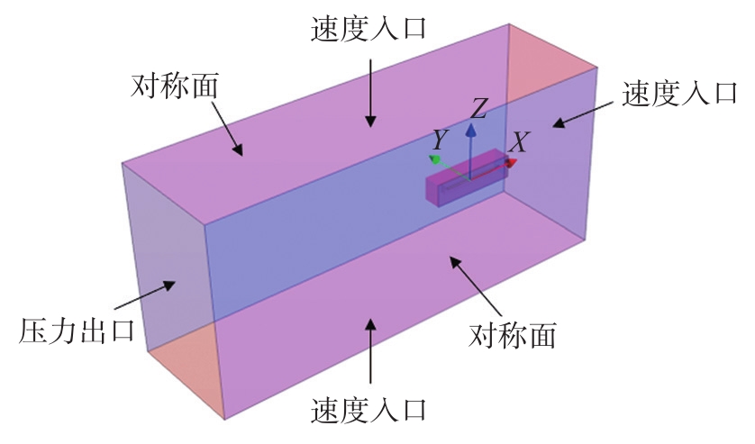
计算流体域的尺寸为:船前方向取2.5倍船长,船后方向取4.5倍船长;船宽方向取2倍船长;船底下方取2倍船长,船体上方取1倍船长。
计算域包括了背景域和重叠域两个部分。建立的数值试验池的顶部、底部以及入口使用速度入口,两侧侧面使用对称面,出口使用压力出口。如图2所示。

Figure 2. Computational domain
在STAR-CCM+软件内对计算域以及模型进行网格划分,采用了重叠网格法。为了保证计算结果的精确性,对船体周围特别是船首船尾处进行了局部加密,并且对自由液面处也进行了局部加密。为了避免反射,使用STAR-CCM+的VOF 波阻尼功能进行消波。运动模拟使用DFBI(Dynamic Fluid Body Interaction)进行求解。模拟时长取100 s。网格划分如图3所示。

Figure 3. Mesh generation
1.1 数值方法


1.2 模型建立
1.3 计算域和网格生成
-
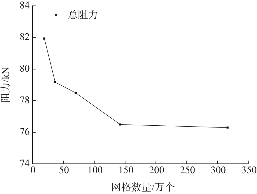
为了保证网格密度以及时间步长取值的合理性,以裸船模型为对象进行对比分析,以
时间步长/s 航速/kn 网格基准尺寸/m 生成网格数量/个 总阻力/kN 0.015 16 0.707 3 166 778 76.290 0.015 16 1.0 1 423 259 76.485 0.015 16 1.414 700 836 78.493 0.015 16 2.0 363 190 79.180 0.015 16 2.828 186 936 81.961 Table 2.
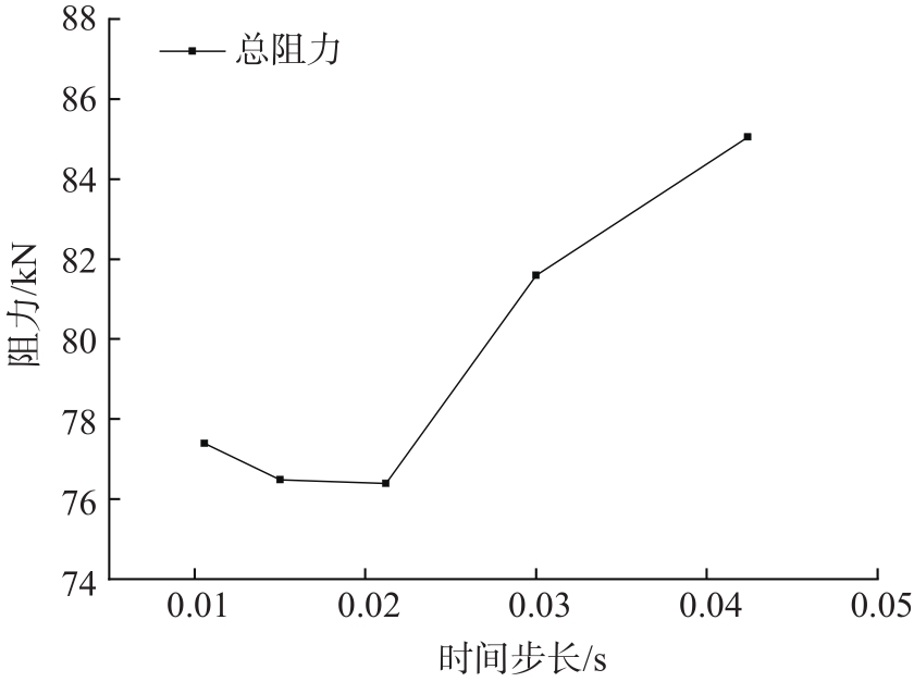
Grid density sensitivity scheme 时间步长/s 航速/kn 网格基准尺寸/m 生成网格数量/个 总阻力/kN 0.0106 16 1.0 1 423 259 77.399 0.0150 16 1.0 1 423 259 76.485 0.0212 16 1.0 1 423 259 76.396 0.0300 16 1.0 1 423 259 81.587 0.0424 16 1.0 1 423 259 85.044 Table 3.
Time step sensitivity scheme 
Figure 4. Grid density sensitivity

Figure 5. Time step sensitivity
可以看出,分别以网格密度和时间步长为变量得出的系列总阻力趋向于稳定,由此可以保证数值模拟的网格密度及时间步长对计算结果没有大的影响。考虑到计算结果精确度以及计算资源耗费,最终选取网格尺寸为1.0 m,网格总数约为1.4×10⁶个,时间步长为0.015 s的方案。
-
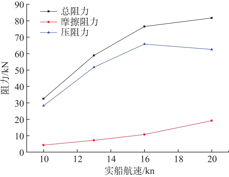
取10 kn,13 kn,16 kn,20 kn四个航速,基于CFD技术得出了此船裸船体的阻力计算曲线,计算时长为100 s,如图6所示,阻力结果如图7和表4所示。由于数值模拟只针对半船进行了计算,所以计算得到的阻力的两倍才是全船的阻力,总阻力由摩擦阻力和压阻力组成。

Figure 6. Total resistance curve of catamaran at each speed

Figure 7. Resistance result curve


航速/kn 总阻力/kN 摩擦阻力/kN 压阻力/kN 0.376 10 32.517 4.271 28.246 0.489 13 58.827 7.200 51.627 0.602 16 76.485 10.700 65.785 0.752 20 81.635 19.112 62.523 Table 4.
Resistance calculation results 可以得出结果:对于本船,总阻力随着航速的增加而增大,在总阻力中,压阻力的占比大于摩擦阻力,减小压阻力是优化此船舶总阻力的有效手段之一。
-
对船舶阻力的优化有很多种,如减小船体表面粗糙度,优化船型,加装压浪板等。
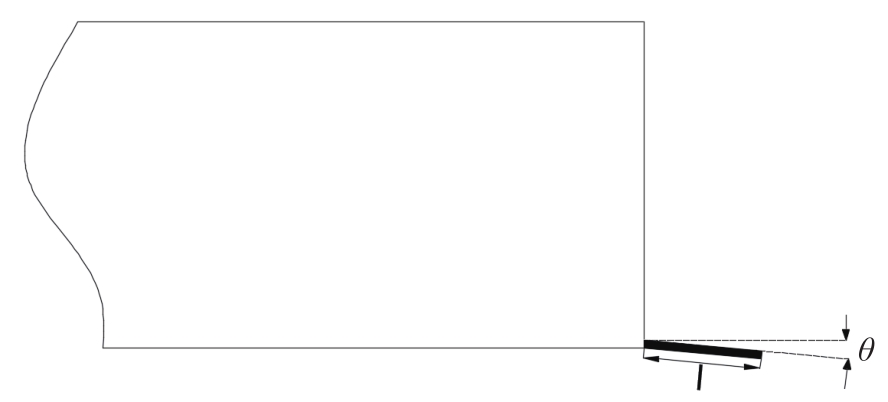
由于加装压浪板的方法对于本船来说相对较为简易,所以本文将加装压浪板作为优化方法,尾压浪板指位于船体艉封板处沿船体底板向后延伸的一块短板,尾压浪板通常有一定的安装角度θ,指的是压浪板与水平面的夹角,如图8所示,压浪板的长度可取船长的1%-2%[16],综合考虑,本文设计的尾压浪板的长度取船长的2%,安装角取0°,5°,7°,厚度均取30 mm。最终得到三种压浪板的方案,压浪板的参数如表5所示。

Figure 8. Schematic diagram of stern flap
压浪板方案 长度/mm 安装角/(°) 方案一 382 0 方案二 382 5 方案三 382 7 Table 5.
stern flap parameters -
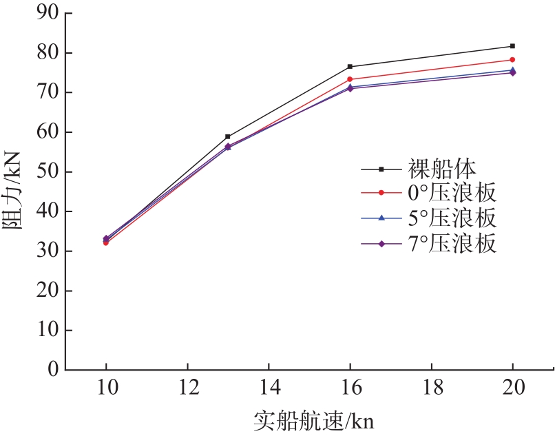
本文针对船舶裸船体及压浪板的三种安装方案,计算10 kn,13 kn,16 kn,20 kn四种航速下的船舶总阻力,如表6所示。
航速/kn 模型 总阻力/kN 减阻效果/% 0.376 10 裸船体 32.517 — 0.376 10 0°压浪板 31.983 1.64 0.376 10 5°压浪板 32.824 -0.94 0.376 10 7°压浪板 33.252 -2.26 0.489 13 裸船体 58.827 — 0.489 13 0°压浪板 56.018 4.78 0.489 13 5°压浪板 56.026 4.76 0.489 13 7°压浪板 56.478 3.99 0.602 16 裸船体 76.485 — 0.602 16 0°压浪板 73.254 4.22 0.602 16 5°压浪板 71.340 6.73 0.602 16 7°压浪板 70.919 7.28 0.752 20 裸船体 81.635 — 0.752 20 0°压浪板 78.222 4.18 0.752 20 5°压浪板 75.665 7.31 0.752 20 7°压浪板 74.954 8.18 Table 6.
Total resistance of each scheme 可以绘制出各个方案的总阻力曲线,如图9所示。

Figure 9. Total resistance curve of each scheme
由计算结果可以分析出:在实船航速大于等于13 kn时,在船尾加装压浪板的减阻效果十分明显,减阻效果均处于3.99%及以上,最大减阻效果达到了8.18%,在16 kn和20 kn航速时,安装角为5°、7°的压浪板的减阻效果优于0°压浪板;在13 kn航速时,各压浪板方案减阻效果接近;在实船航速为10 kn时,在船尾加装压浪板的减阻效果比较差,几乎失去了减阻效果。压浪板的减阻效果主要是因为安装了压浪板之后,通过增加船体的虚长度影响尾部的流场[17],降低尾部相应波区的波高,减少船舶的兴波阻力,进而减少船舶总阻力,可见本文4.4节的波形图分析。
-
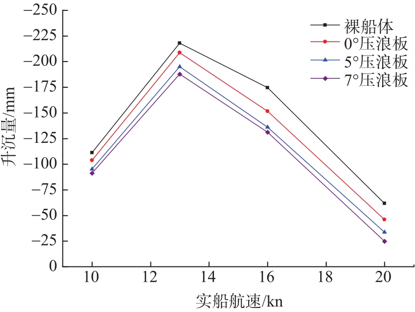
本文还分析了在船尾加装压浪板对于船舶航态中的升沉的影响,如表7所示。
航速/kn 模型 升沉量/mm 升沉量降低/% 0.376 10 裸船体 -111.23 — 0.376 10 0°压浪板 -103.73 6.74 0.376 10 5°压浪板 -95.12 14.48 0.376 10 7°压浪板 -91.27 17.94 0.489 13 裸船体 -217.88 — 0.489 13 0°压浪板 -208.76 4.19 0.489 13 5°压浪板 -194.88 10.56 0.489 13 7°压浪板 -187.68 13.86 0.602 16 裸船体 -174.54 — 0.602 16 0°压浪板 -151.52 13.19 0.602 16 5°压浪板 -136.11 22.02 0.602 16 7°压浪板 -131.10 24.89 0.752 20 裸船体 -61.78 — 0.752 20 0°压浪板 -46.03 25.50 0.752 20 5°压浪板 -33.58 45.64 0.752 20 7°压浪板 -24.77 59.91 Table 7.
Heave of each scheme 可以绘制出各个方案的升沉量曲线,如图10所示。

Figure 10. Heave curve of each scheme
由计算结果可以分析出:加装压浪板对于船舶航态的升沉有着一定的影响,在16 kn以及20 kn的较高航速下,加装压浪板对升沉量的降低效果较大,均处于13.19%及以上,最大降低效果达到了59.91%;在其他航速下,加装安装角为0°时的压浪板对于升沉量的降低效果相对较小;各航速下加装安装角为5°的压浪板对于船舶升沉量的降低效果均大于安装角为0°的压浪板,安装角为7°的压浪板的降低效果大于安装角为5°的压浪板。
-
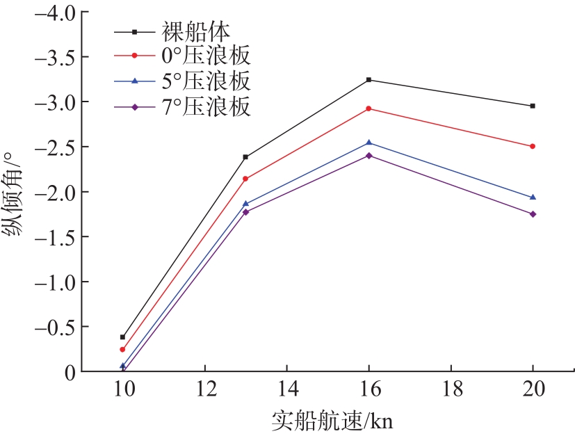
本文还分析了在船尾加装压浪板对于船舶航态中的纵倾的影响,如表8所示。
航速/kn 模型 纵倾角/(°) 纵倾角降低/% 0.376 10 裸船体 -0.38 — 0.376 10 0°压浪板 -0.24 37.79 0.376 10 5°压浪板 -0.06 85.45 0.376 10 7°压浪板 0.01 102.64 0.489 13 裸船体 -2.38 — 0.489 13 0°压浪板 -2.14 10.13 0.489 13 5°压浪板 -1.86 21.76 0.489 13 7°压浪板 -1.77 25.62 0.602 16 裸船体 -3.24 — 0.602 16 0°压浪板 -2.92 9.80 0.602 16 5°压浪板 -2.54 21.66 0.602 16 7°压浪板 -2.40 25.92 0.752 20 裸船体 -2.95 — 0.752 20 0°压浪板 -2.50 15.24 0.752 20 5°压浪板 -1.93 34.64 0.752 20 7°压浪板 -1.75 40.66 Table 8.
Trim angle of each scheme 可以绘制出各个方案的纵倾角曲线,如图11所示。

Figure 11. Trim angle curve of each scheme
由计算结果可以分析出:加装压浪板对于船舶航态的纵倾角有着一定的影响,在各个航速下,对于纵倾角的降低效果均处于9.80%及以上,最大降低效果达到了102.64%;加装安装角为5°的压浪板对于船舶纵倾角的降低效果大于安装角为0°的压浪板,安装角为7°的压浪板的降低效果大于安装角为5°的压浪板。需要注意,当加装安装角为7°的压浪板后,船舶在10 kn航速下航行时,可能会出现轻微的艏倾现象。
-
加装压浪板可以改变航态主要是因为在船舶航行过程中,压浪板可以使船舶产生附加力矩,进而改变船舶的航态。
-
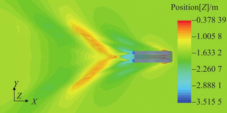
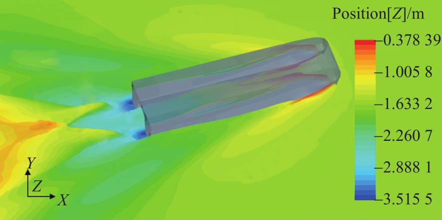
将实船16 kn(

Figure 12. 16 kn waveform of bare hull

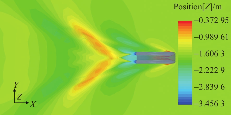
Figure 13. 16 kn waveform of 0° stern flap

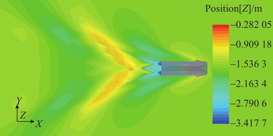
Figure 14. 16 kn waveform of 5° stern flap

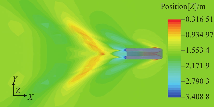
Figure 15. 16 kn waveform of 7° stern flap

Figure 16. Oblique view of bare hull 16 kn waveform

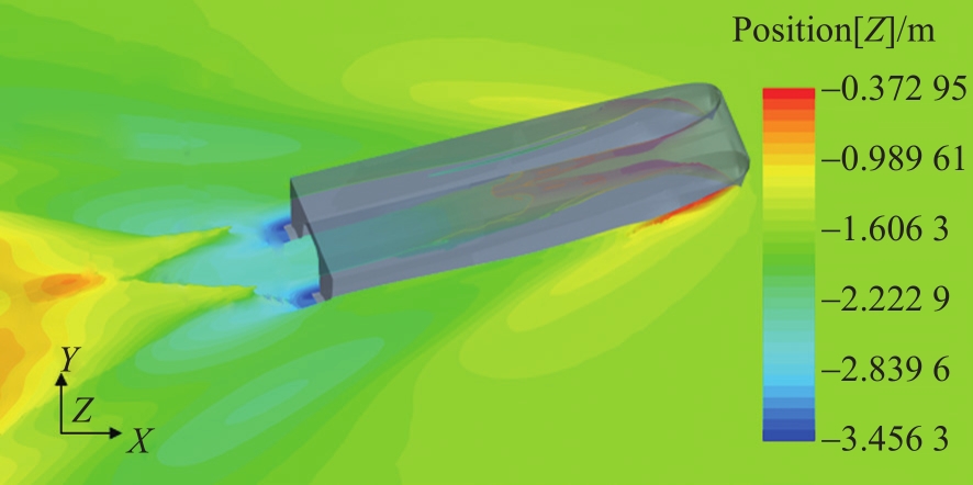
Figure 17. Oblique view of 16 kn waveform of 0° stern flap

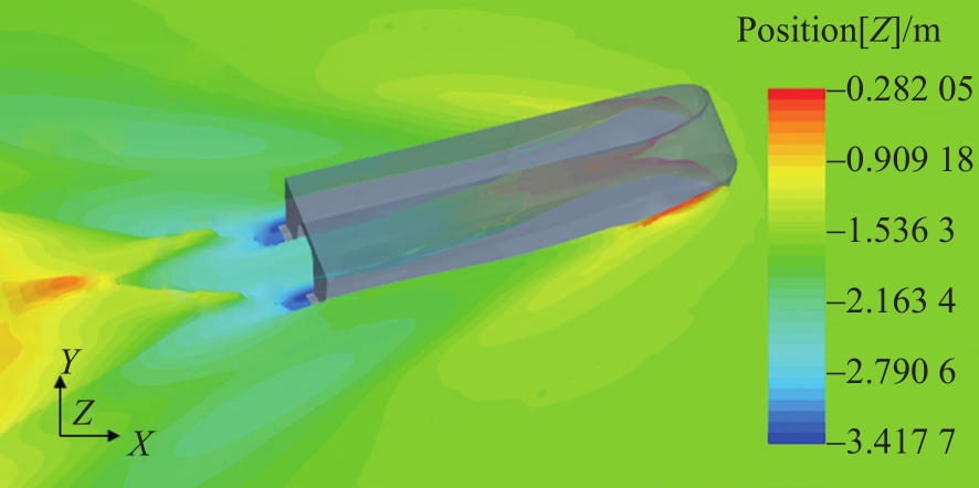
Figure 18. Oblique view of 16 kn waveform of 5° stern flap

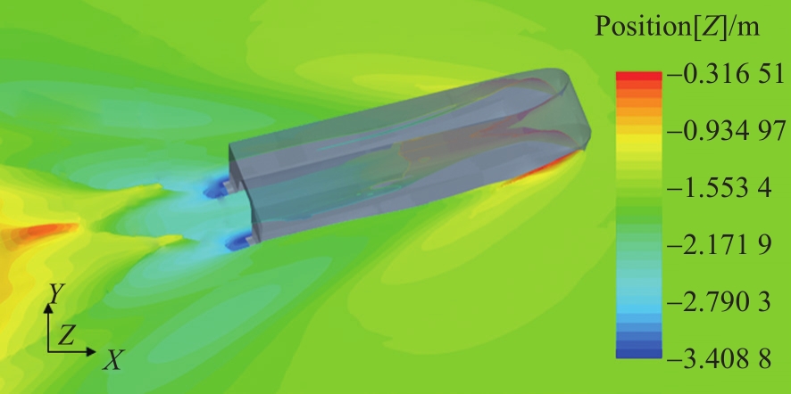
Figure 19. Oblique view of 16 kn waveform of 7° stern flap
由波形图可以看出,安装压浪板的船体,虚长度比裸船体稍长,而安装角为5°及7°的压浪板的虚长度更长。压浪板的安装会有效降低尾部相应波区的波高值,降低船舶兴波阻力,最终降低船舶的总阻力。
4.1 优化方法
4.2 减阻效果分析
4.3 船舶航态分析
4.3.1 升沉分析
4.3.2 纵倾分析
4.3.3 航态改变分析
4.4 波形图分析
-
文章基于CFD方法对本双体船的阻力进行了数值模拟计算,对四个航速下的总阻力进行分析,在总阻力中,压阻力的占比大于摩擦阻力。
在船尾加装压浪板可以降低此船的阻力,并且改变船舶航行时的升沉量、纵倾角。阻力方面:随着航速增加,压浪板的减阻效果也随之增大,在较高航速时,减阻效果尤为明显。且在给定的安装角范围内,随着船体加装压浪板的安装角角度增加,减阻效果也随之增大;升沉量方面:在较高航速时,对升沉量的降低效果尤为明显。在给定的安装角范围内,随着压浪板的安装角角度增加,升沉量降低效果也随之增大;纵倾角方面:在各个航速下,对于船舶纵倾角都有一定的降低效果。在给定的安装角范围内,随着压浪板的安装角角度增加,纵倾角降低效果也随之增大。
综上所述,在船尾加装合适的压浪板对双体船的阻力性能有一定的改善效果,同时也能改变船舶的航态,可以为本船的性能优化提供参考。

 DownLoad: