• Peer Review
  • Non-profit
  • Global Open Access
  • Green Channel for Rising Stars
Volume 9 Issue 2
Jun.  2022
Turn off MathJax
Article Contents

XU Xuesong, HUANG Ya, LEI Hong, JIANG Li, ZHANG Jie, WANG Kun. Research on the High Power Magnetic Field Immunity Test System for ITER[J]. SOUTHERN ENERGY CONSTRUCTION, 2022, 9(2): 26-32. doi: 10.16516/j.gedi.issn2095-8676.2022.02.003
Citation: XU Xuesong, HUANG Ya, LEI Hong, JIANG Li, ZHANG Jie, WANG Kun. Research on the High Power Magnetic Field Immunity Test System for ITER[J]. SOUTHERN ENERGY CONSTRUCTION, 2022, 9(2): 26-32. doi: 10.16516/j.gedi.issn2095-8676.2022.02.003

Research on the High Power Magnetic Field Immunity Test System for ITER

doi: 10.16516/j.gedi.issn2095-8676.2022.02.003
  • Received Date: 2022-03-31
  • Rev Recd Date: 2022-05-08
  • Available Online: 2022-06-02
  • Publish Date: 2022-06-25
  •   Introduction  To ensure the safe and stable operation of the equipment, the power electronic equipment regulated by the International Thermonuclear Experimental Reactor (ITER) organization must pass the relevant magnetic field immunity test.   Method  Based on ITER requirements, the parameter requirements of the required test system were defined. Square solenoid coil and square three coil were selected as the research objects. The structural parameters of the optimal performance were calculated by numerical calculation method, and the correctness of the calculation was verified by finite element method.   Result  Compared with the two coil types, the solenoid with low power consumption is selected as the final structure. Then, based on this parameter, the power topology of DC transient is analyzed, the relevant parameters are calculated, and the performance data required by the final power supply is determined.   Conclusion  The research of this paper provides a detailed calculation process and design reference for the design of induction coil and its power supply of ITER high-power magnetic field immunity test system.
  • [1] 黄亚. ITER大口径均匀强磁兼容测试装备研制 [D]. 合肥: 中国科学技术大学, 2021. DOI: 10.27517/d.cnki.gzkju.2021.000074.

    HUANG Y. The development of the large-caliber uniform high intensity magnetic compatibility test equipment for ITER [D]. Hefei: University of Science and Technology of China, 2021. DOI: 10.27517/d.cnki.gzkju.2021.000074.
    [2] RYFF, PETER F. Current distribution in helical solenoids [J]. Industry Applications, IEEE Transactions on, 1972, IA-8(4): 485-490. DOI:  10.1109/TIA.1972.349840.
    [3] CONWAY J T. Exact solutions for the magnetic fields of axisymmetric solenoids and current distributions [J]. Magnetics IEEE Transactions on, 2001, 37(4): 2977-2988. DOI:  10.1109/20.947050.
    [4] LIN Q G. An approach to the magnetic field of a finite solenoid with a circular cross-section [J]. European Journal of Physics, 2021, 42(3): 035206. DOI:  10.1088/1361-6404/abd4c8.
    [5] FIRESTER, ARTHUR H. Design of square helmholtz coil systems [J]. Review of Scientific Instruments, 1966, 37(9): 1264-1265. DOI:  10.1063/1.1720478.
    [6] CROSSER M S, SCOTT S, CLARK A, et al. On the magnetic field near the center of Helmholtz coils [J]. Review of Scientific Instruments, 2010, 81(8): 832-380. DOI:  10.1063/1.3474227.
    [7] BEIRANVAND R. Analyzing the uniformity of the generated magnetic field by a practical one-dimensional helmholtz coils system [J]. Review of Scientific Instruments, 2013, 84(7): 08D904-1. DOI:  10.1063/1.4813275.
    [8] BEIRANVAND R. Effects of the winding cross-section shape on the magnetic field uniformity of the high field circular helmholtz coil systems [J]. IEEE Transactions on Industrial Electronics, 2017, 64(9): 7120-7131. DOI:  10.1109/TIE.2017.2686302.
    [9] YANG Y, SONG Z Q, JIANG L, et al. An improved two-coil configuration for low-frequency magnetic field immunity tests and its field inhomogeneity analysis [J]. IEEE Transactions on Industrial Electronics, 65(10): 8204-8214. DOI:  10.1109/TIE.2018.2807420.
    [10] HUANG Y, FU P, JIANG L, et al. Design and error analysis of a large-caliber steady-state magnetic-field testing system [J]. IEEE Transactions on Magnetics, 2020, 56(99): 1-9. DOI:  10.1109/TMAG.2019.2958567.
    [11] HUANG Y, JIANG L, FU P, et al. Optimal design method to improve the magnetic field distribution of multiple square coil systems [J]. IEEE Access, 2020, 8(9): 171184-171194. DOI:  10.1109/ACCESS.2020.3024653.
    [12] HUANG Y, JIANG L , FU P , et al. Temperature field calculation and water cooling design of the magnetic field immunity testing system [J]. Fusion Engineering and Design, 2021, 170(9): 112515. DOI:  10.1016/j.fusengdes.2021.112515.
    [13] GOTTARDI G, MESIRCA P, AGOSTINI C, et al. A four coil exposure system (tetracoil) producing a highly uniform magnetic field [J]. Bioelectromagnetics, 2003, 24(2): 125. DOI:  10.1002/bem.10074.
    [14] PANG H, DUAN L, QUAN W, et al. Design of highly uniform three dimensional spherical magnetic field coils for atomic sensors [J]. IEEE Sensors Journal, 2020, 20(19): 11229-11236. DOI:  10.1109/JSEN.2020.2997800.
    [15] RUBENS, SIDNEY M. Cube‐surface coil for producing a uniform magnetic field [J]. Review of Scientific Instruments, 1945, 16(9): 243-245. DOI:  10.1063/1.1770378.
    [16] PA N D, LIN S, LI L, et al. Research on the design method of uniform magnetic field coil based on the MSR [J]. IEEE Transactions on Industrial Electronics, 2019, 67(2): 1348-1356. DOI:  10.1109/TIE.2019.2899544.
    [17] XU J, KANG X, FAN Z, et al. Design of highly uniform magnetic field coils with wolf pack algorithm [J]. IEEE Sensors Journal, 2020, 21(4): 4412-4424. DOI:  10.1109/JSEN.2020.3030622.
    [18] YONG H H, HAN B H, LEE S Y. Magnetic propulsion of a magnetic device using three square-helmholtz coils and a square-Maxwell coil [J]. Medical & Biological Engineering & Computing, 2010, 48(2): 139. DOI:  10.1007/s11517-009-0574-5.
    [19] JIN Y X, LI L Y, PAN D H, et al. Analysis and design of a uniform magnetic field coil with a magnetic shield based on an improved analytical model [J]. IEEE Transactions on Industrial Electronics, 2021, 69(3): 3068-3077. DOI:  10.1109/TIE.2021.3066929.
    [20] ALLDRED J C, SCOLLAR I. Square cross section coils for the production of uniform magnetic fields [J]. Journal of Scientific Instruments, 1967, 44(9): 755. DOI:  10.1088/0950-7671/44/9/327.
    [21] MERRITT R, PURCELL C, STROINK G. Uniform magnetic field produced by three, four, and five square coils [J]. Review of Scientific Instruments, 1983, 54(7): 879-882. DOI:  10.1063/1.1137480.
  • 通讯作者: 陈斌, bchen63@163.com
    • 1. 

      沈阳化工大学材料科学与工程学院 沈阳 110142

    1. 本站搜索
    2. 百度学术搜索
    3. 万方数据库搜索
    4. CNKI搜索

Figures(13)  / Tables(5)

Article Metrics

Article views(260) PDF downloads(50) Cited by()

Related

Research on the High Power Magnetic Field Immunity Test System for ITER

doi: 10.16516/j.gedi.issn2095-8676.2022.02.003

Abstract:   Introduction  To ensure the safe and stable operation of the equipment, the power electronic equipment regulated by the International Thermonuclear Experimental Reactor (ITER) organization must pass the relevant magnetic field immunity test.   Method  Based on ITER requirements, the parameter requirements of the required test system were defined. Square solenoid coil and square three coil were selected as the research objects. The structural parameters of the optimal performance were calculated by numerical calculation method, and the correctness of the calculation was verified by finite element method.   Result  Compared with the two coil types, the solenoid with low power consumption is selected as the final structure. Then, based on this parameter, the power topology of DC transient is analyzed, the relevant parameters are calculated, and the performance data required by the final power supply is determined.   Conclusion  The research of this paper provides a detailed calculation process and design reference for the design of induction coil and its power supply of ITER high-power magnetic field immunity test system.

XU Xuesong, HUANG Ya, LEI Hong, JIANG Li, ZHANG Jie, WANG Kun. Research on the High Power Magnetic Field Immunity Test System for ITER[J]. SOUTHERN ENERGY CONSTRUCTION, 2022, 9(2): 26-32. doi: 10.16516/j.gedi.issn2095-8676.2022.02.003
Citation: XU Xuesong, HUANG Ya, LEI Hong, JIANG Li, ZHANG Jie, WANG Kun. Research on the High Power Magnetic Field Immunity Test System for ITER[J]. SOUTHERN ENERGY CONSTRUCTION, 2022, 9(2): 26-32. doi: 10.16516/j.gedi.issn2095-8676.2022.02.003
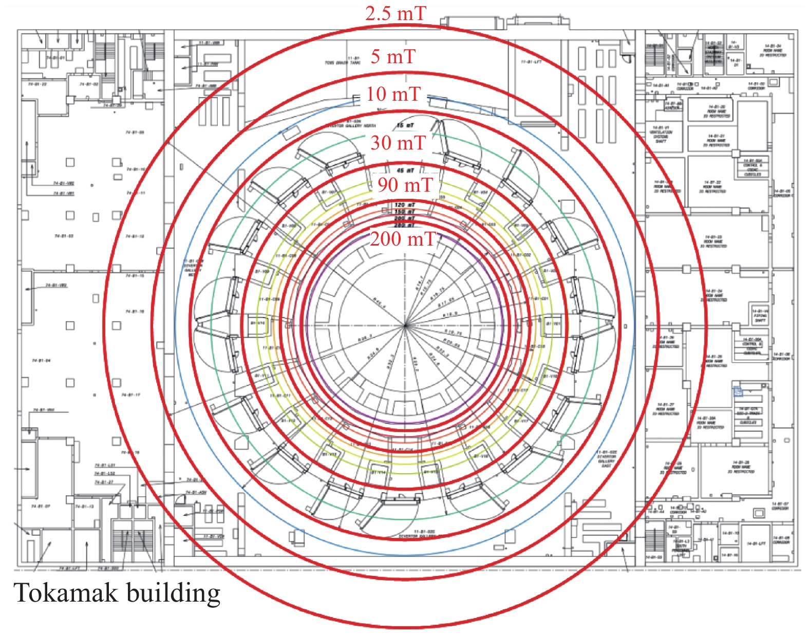
    • 随着磁约束聚变的发展,托卡马克装置的参数越来越高,周围环境中会产生非常强的空间磁场;同时,等离子体破裂过程时电流迅速衰减,形成很大的瞬态磁场。如图1所示,ITER装置周围的最大稳态磁场超过200 mT最大磁场变化率也超过7 T/s[1],这种高强度的空间杂散磁场会影响主厅内与聚变装置相关部件和系统的稳定运行。

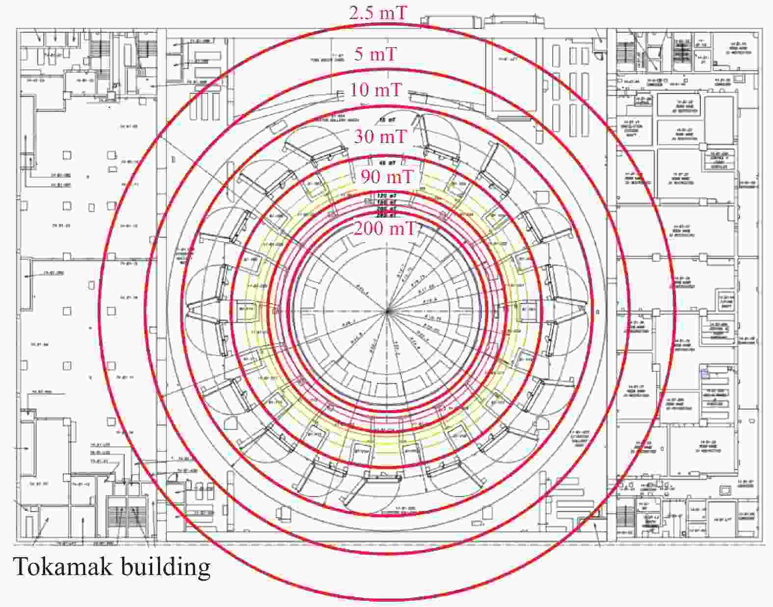
      Figure 1.  Maximum steady-state magnetic field distribution around ITER Tokamak

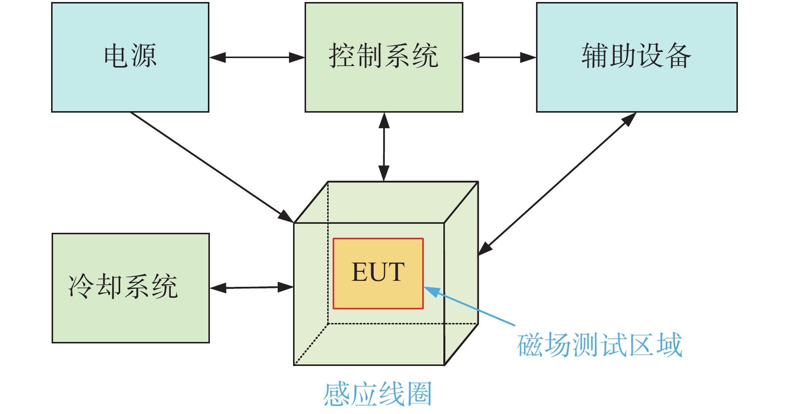
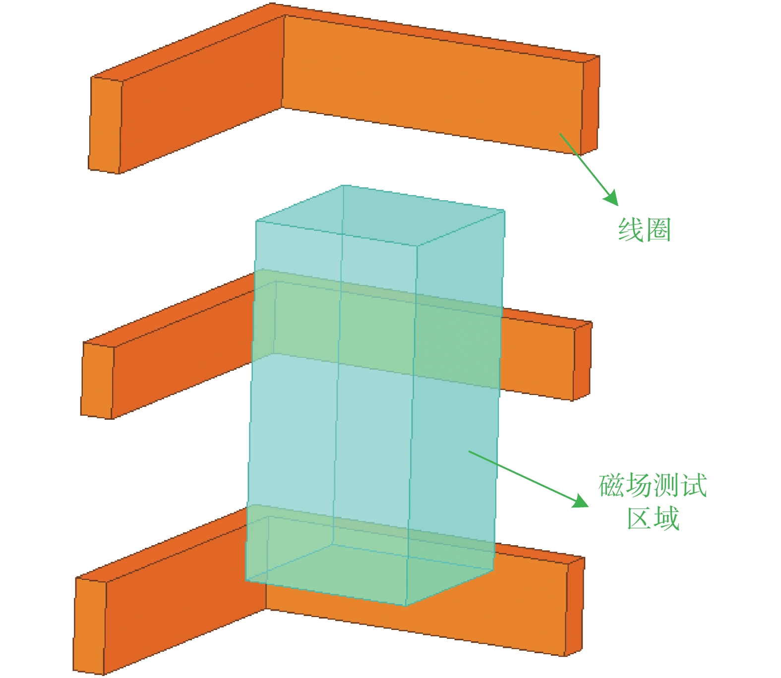
      强磁场引起的电磁干扰是托卡马克装置及其电源系统的一个独特问题。开展电磁干扰研究,解决干扰问题,对保证托卡马克装置的正常运行和物理实验的发展具有重要意义。ITER组织计划建设一个高功率磁场抗扰度测试系统以验证被测部件能够在对应环境下可靠工作,如图2所示。同时,随着聚变装置所用的变流器容量增大和非同相逆并联结构的应用,强磁场电磁干扰问题在工业中日益突出。因此,该平台的成功构建也可以为业界的EMC测试提供必要的手段。

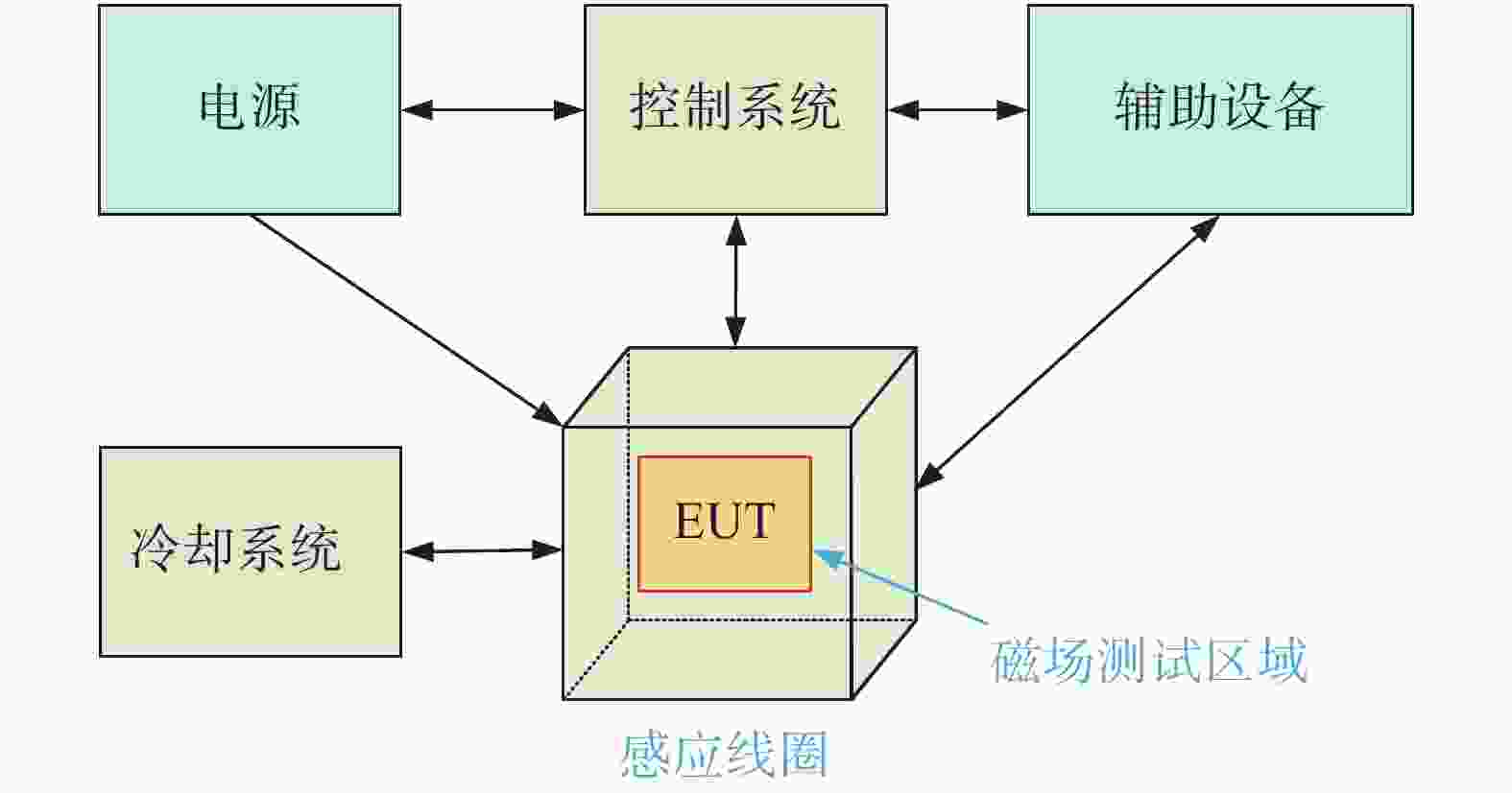
      Figure 2.  Diagram of the high power magnetic field immunity test system

      磁场抗扰度测试需要在X、YZ三个正交方向上进行,因此磁场均匀区域最好是一个立方体。而在ITER组织规定中,产生均匀磁场的尺寸为2.1 m×2.1 m×2.1 m [1]。为了计算方便,引入以下参数:

      1) 最小磁场(Bmin):均匀区域内磁感应强度的最小值。

      2) 最大磁场(Bmax):均匀区域内磁感应强度的最大值。

      3) 磁场均匀度(η):最大和最小磁场的比值。

      $$ \eta = \frac{{{B_{\max }}}}{{{B_{\min }}}} $$ (1)

      高功率磁场抗扰度测试系统核心部件是能产生均匀磁场的感应线圈,目前主要包括螺线管线圈、亥姆霍兹线圈、多线圈组和三维正交线圈等结构。螺线管线圈是一种常见的结构,世界各地的科学家已经对这些线圈的结构、原理、测试和应用进行了研究[2-4]。亥姆霍兹线圈结构简单,是研究最多的形式,相关科研工作者做了设计[5],对其磁场均匀性进行了研究[6-7],对于其结构、原理和优化有着详细的分析[8-9]。而对于需要更高磁场均匀性的场合,可以使用多线圈组结构,科学家们研究了不同线圈组的磁场均匀性,包括三线圈系统的研制[10-12],四线圈系统的设计[13],三维球形线圈[14]研究,并进行更多的改进优化方案[15-17]。正交线圈结构也有相应的阐述[18-19]。由于方形结构在大型设备的制造和焊接过程中比圆形具有更多优势[20-21],因此ITER组织[1]和IEC(国际电工委员会)在磁场抗扰度试验中推荐了方形结构。

    • 对于ITER的空间磁场形态主要包括稳态磁场即瞬态变化磁场,需要进行稳态和瞬态磁场测试。

    • 稳态磁场测试用于托卡马克装置周围强磁环境中敏感设备和部件的EMC测试,也可用于变流器周围敏感设备和部件的测试。其核心是直流磁场感应线圈和直流电源系统。

      直流磁场感应线圈主要用于在特定的区域内产生一定强度的均匀磁场。本测试标准参照ITER组织设计,其磁场均匀性不大于1.4。由于ITER托卡马克装置周围的磁场高达0.2 T,考虑到未来托卡马克装置的更高参数需求,试验线圈的实际最大试验容量选择为0.5 T。

      根据试验的具体要求,需要设计两套试验线圈。第一组2.1 m/0.5 T线圈可在2.1 m×2.1 m×2.1 m的立方体空间内产生至少0.5 T的均匀稳态磁场,磁场均匀性设计指标取1.3。主要用于大型设备和部件的电磁兼容测试。第二组1 m/0.5 T线圈可在1 m×1 m×1 m 的立方体空间内产生至少0.5 T的均匀稳态磁场,磁场均匀性设计指标取1.1。除了对小型设备和部件进行电磁兼容测试外,还可以用于某些设备和部件的故障等级测试和故障机理研究。

    • 瞬变磁场测试主要用于托卡马克装置相关敏感设备在等离子体破裂条件下,在强瞬变磁场作用下的电磁兼容性测试。电路如图3所示。RL是电感和电阻,R0是能量放电电阻。首先,线圈由电源充电,然后进行放电,会形成较高的di/dt,产生符合要求的磁场变化率。在ITER托卡马克装置最严重的17 MA/41 ms主破裂期间产生的瞬变磁场为7 T/s,持续时间为41 ms。同样,考虑到装置未来可能更严重的破裂,试验中的磁场变化率选14~30 T/s,并维持50 ms。

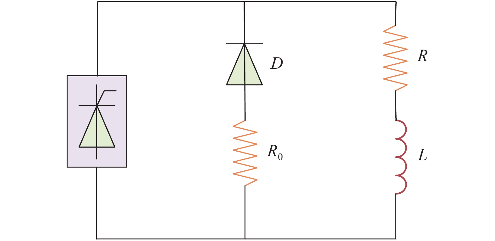
      Figure 3.  Circuit topology of DC transient magnetic field test

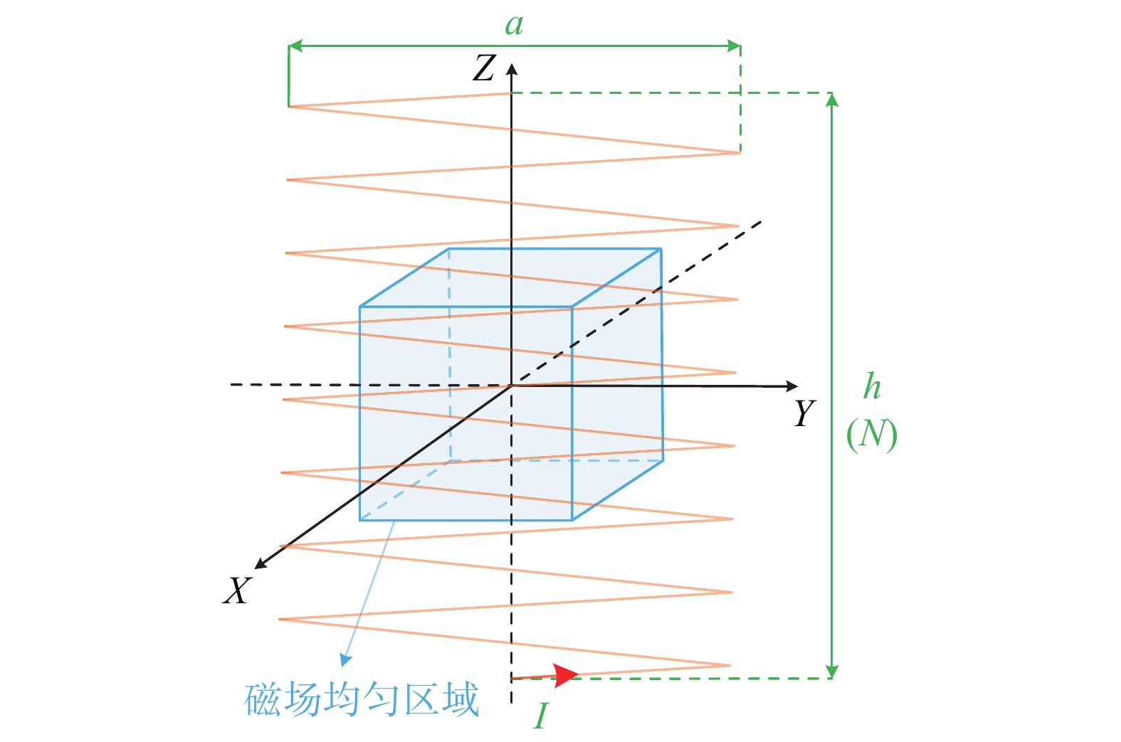
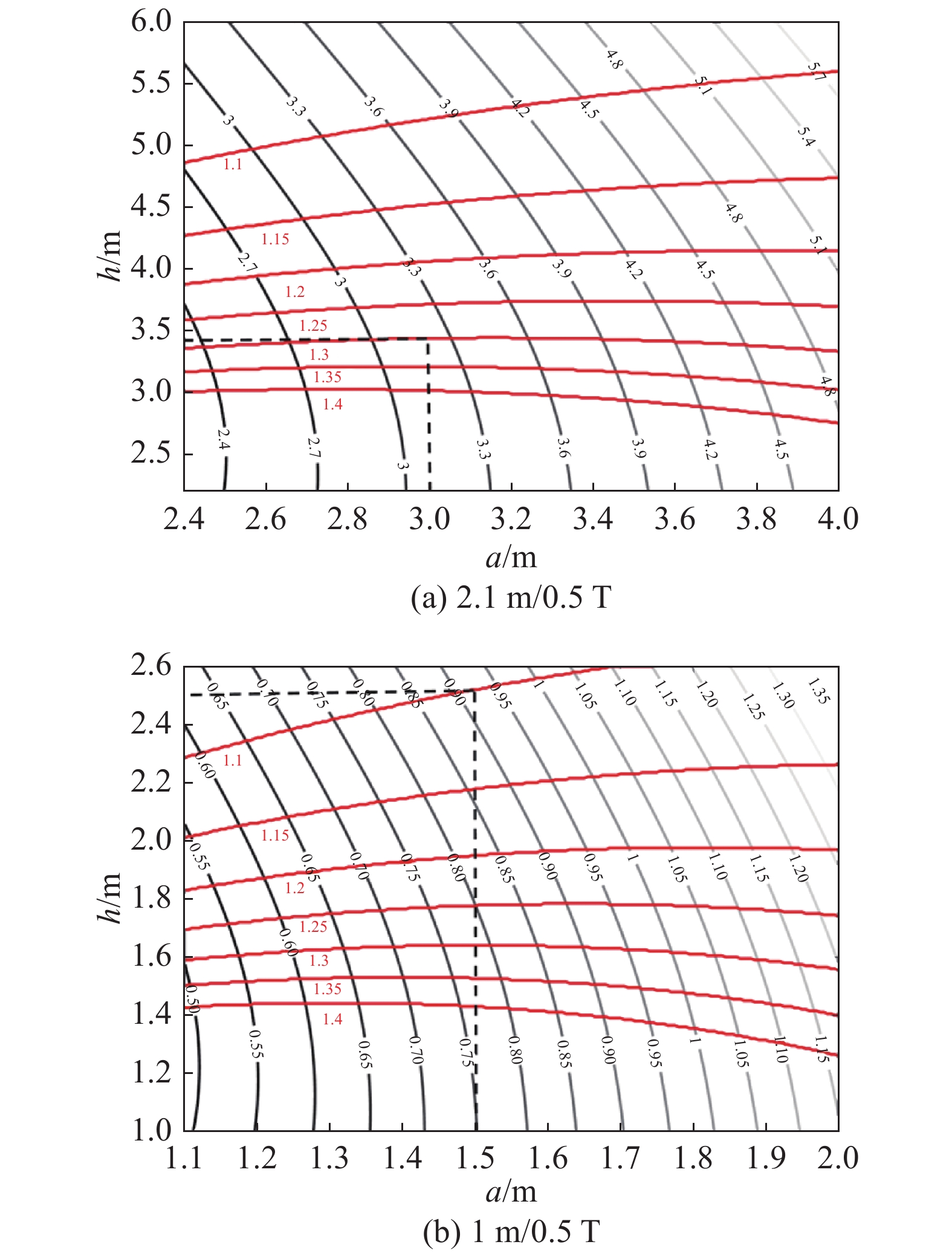
    • 方形螺线管线圈如图4所示,线圈平均边长a和线圈轴向高度h以及安匝数为NI。基于理想模型,通过磁场数值计算得到了2.1 m/0.5 T和1 m/0.5 T条件下磁场均匀度η和总线圈损耗P相对于线圈尺寸(ah)的分布,如图5所示。导体电流密度取为J=4 A/mm2

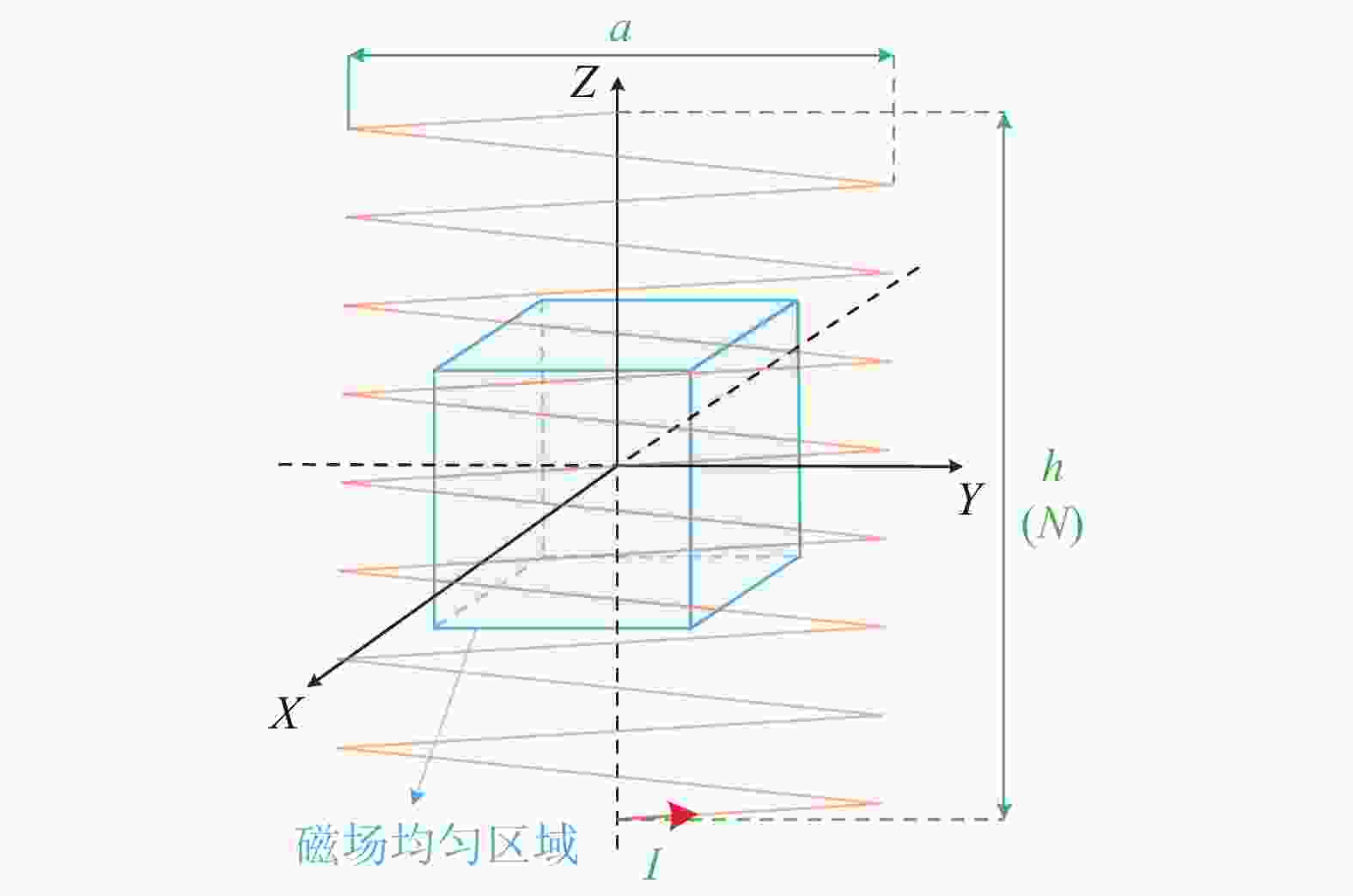
      Figure 4.  Solenoid configuration

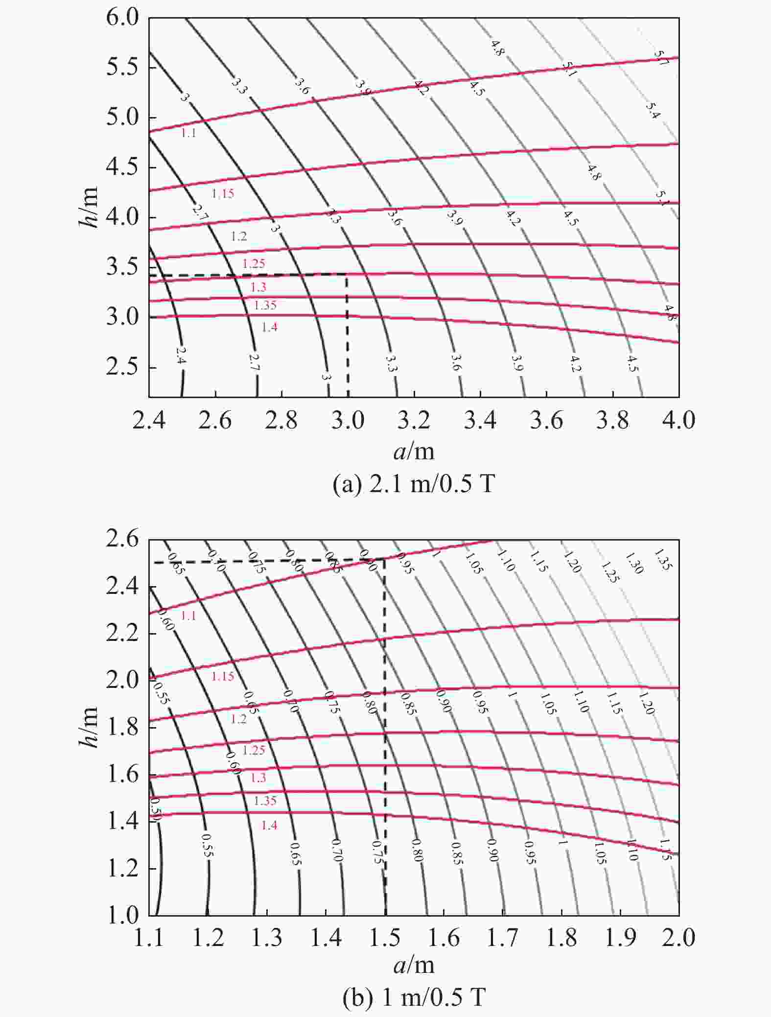
      Figure 5.  Relationship between magnetic field uniformity, power loss and structural parameters

      通过图5提取线圈参数,如表1所示。

      类型2.1 m/0.5 T1 m/0.5 T
      导体截面/mm2200×60200×60
      匝数5036
      绝缘间距/mm1010
      横向尺寸2.8 m/3.2 m1.3 m/1.7 m
      纵向尺寸/m3.492.51
      总重量/t19.57.0
      电流/kA45.035.6
      电感/mH5.270.983
      电阻/mΩ1.4700.514
      功耗/MW2.9810.651

      Table 1.  Basic parameters of square solenoid coil

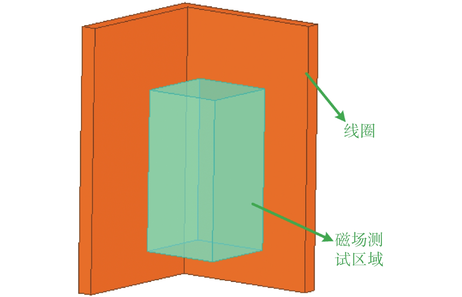
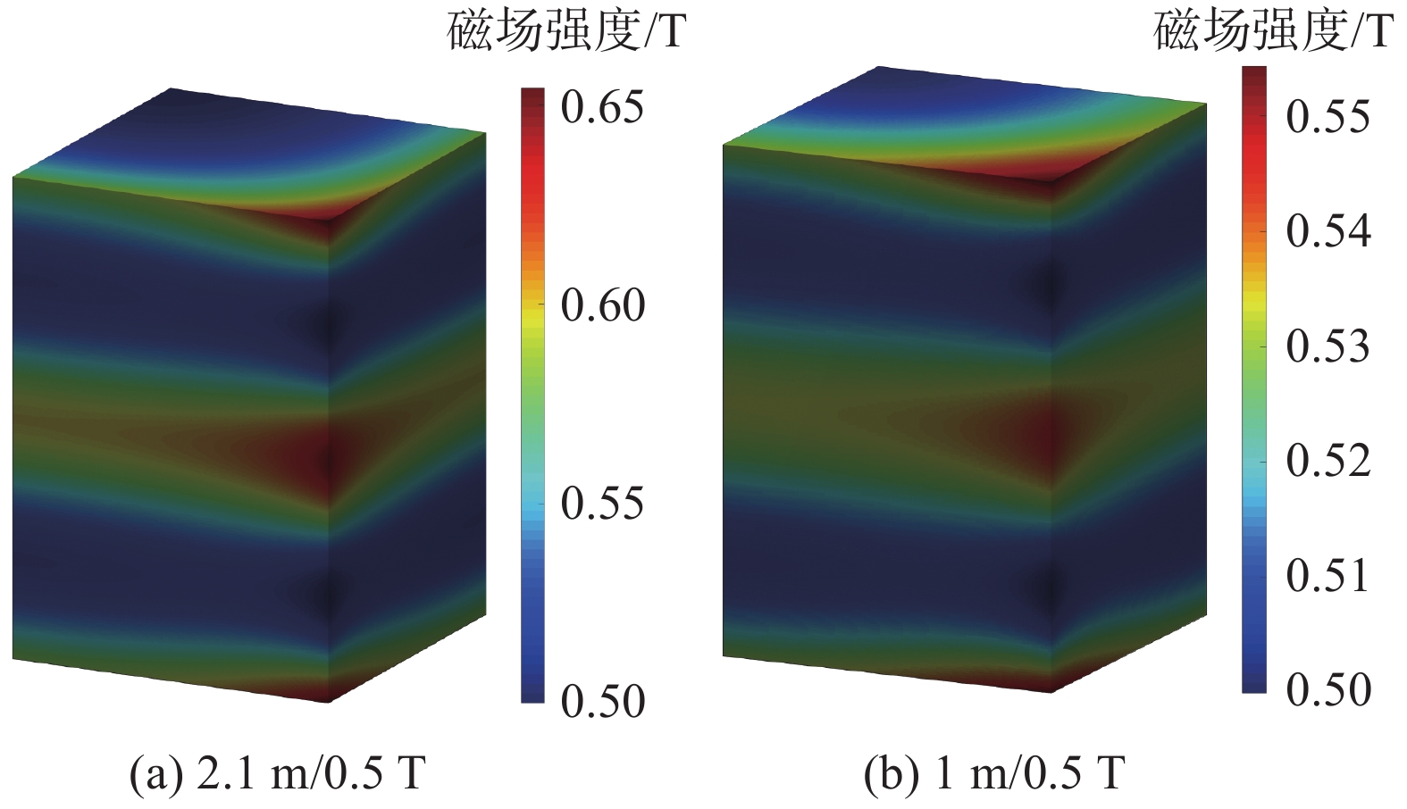
      图6所示为有限元仿真模型,计算磁场情况,如图7所示。对于2.1 m/0.5 T结构,最小磁场为500.0 mT,最大值为648.2 mT,磁场均匀性为1.296。对于1 m/0.5 T结构,最小磁场500.0 mT,最大磁场为550.9 mT,磁场均匀性为1.102。

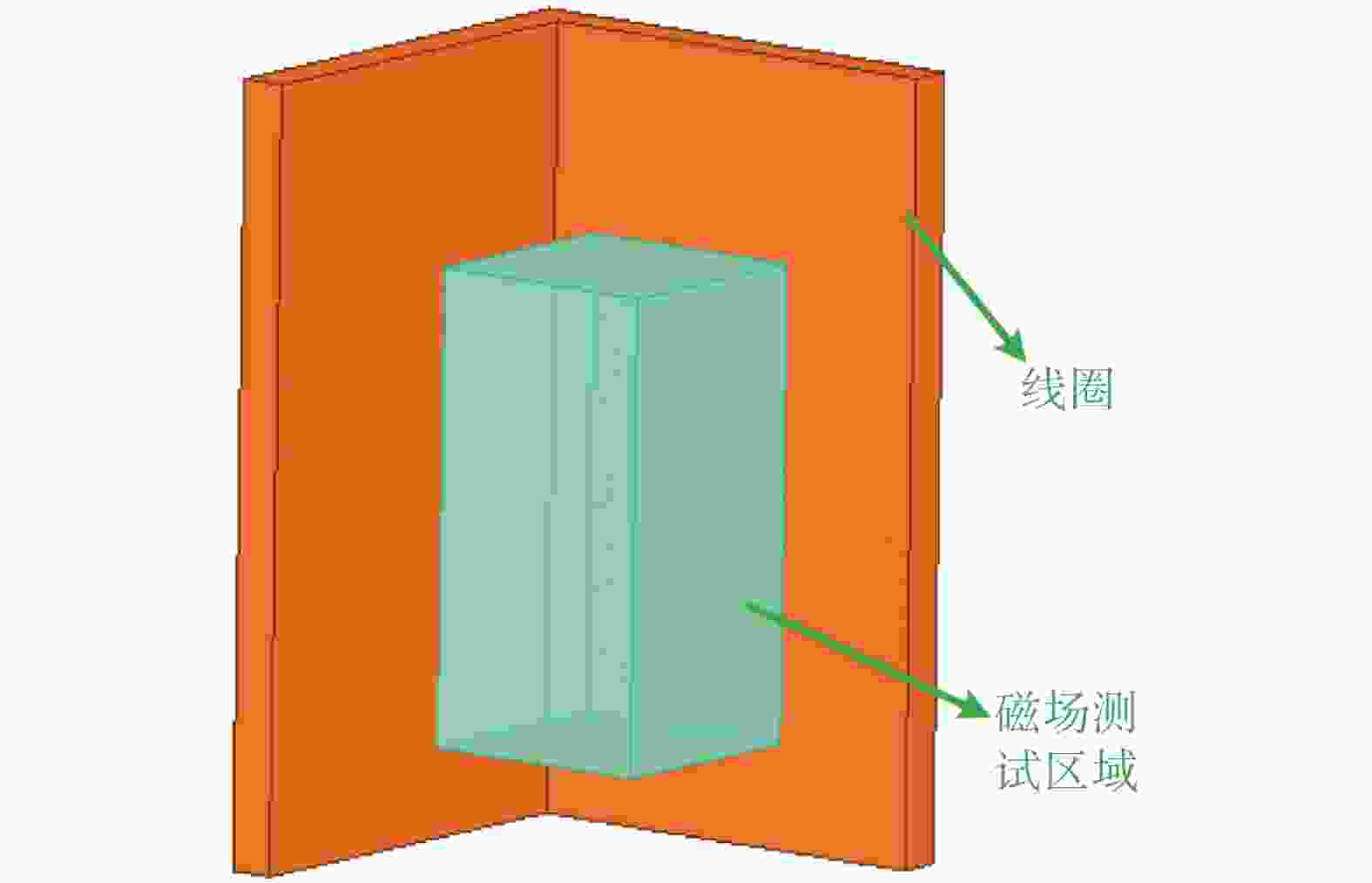
      Figure 6.  1/4 model of the solenoid coil

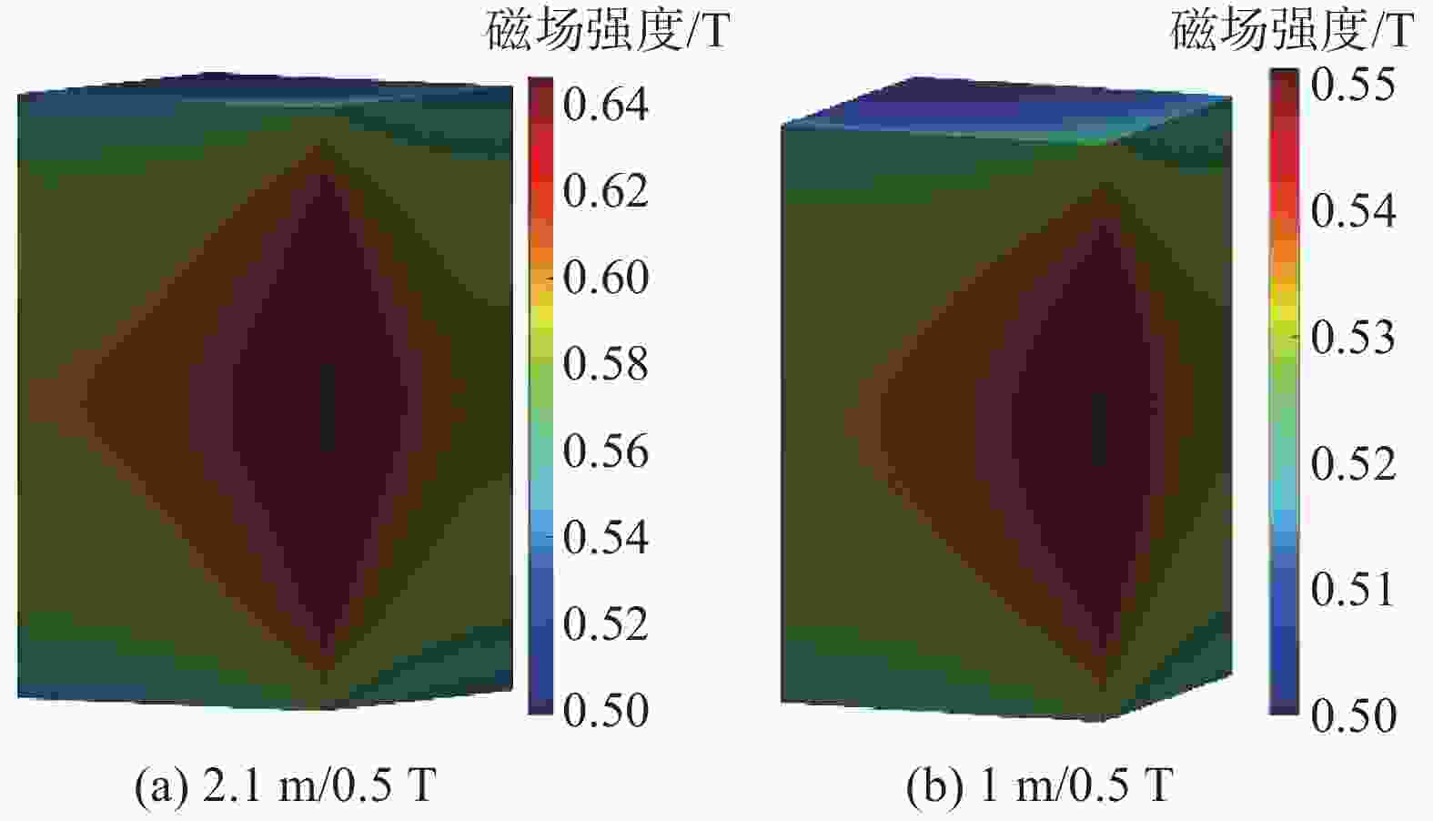
      Figure 7.  Magnetic field distribution (1/4) of the solenoid coil in the test area
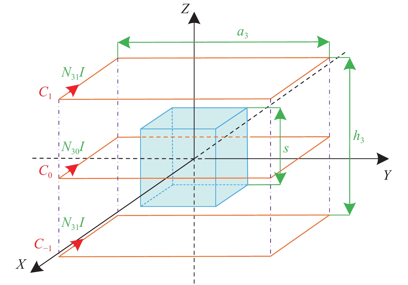
    • 三线圈结构如图8所示。有三组线圈(C1C0C−1):边长为a3,两个侧边线圈之间的距离为h3,两侧的安匝数为N31I,中间线圈的安匝数为N30I。侧线圈与中间线圈的匝数比定义为β3,可描述为

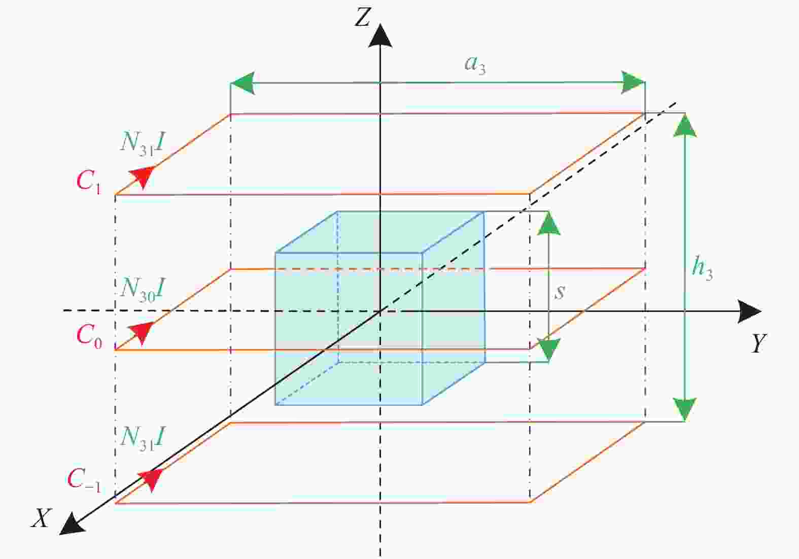
      Figure 8.  Three-coil configuration

      $$ \left\{ \begin{gathered} {\beta _3}{\text{ = }}{{{N_{31}}} \mathord{\left/ {\vphantom {{{N_{31}}} {{N_{30}}}}} \right. } {{N_{30}}}} \\ {M_3}{\text{ = }}{N_{30}}I + 2{N_{31}}I \\ \end{gathered} \right. $$ (2)

      式中:

      M3——线圈的总安匝数。

      最佳磁场均匀性参数之间的关系为[9]:

      $$ \left\{ \begin{gathered} \dfrac{{{a_3}}}{s} = 1.392{\text{ + }}176.2{{\rm{e}}^{ - 5.601\eta }} \\ {\beta _3} = 1.029{\text{ + }}27.82{{\rm{e}}^{ - 3.532\eta }} \\ \dfrac{{{h_3}}}{s} = 0.9442 \cdot \dfrac{{{a_3}}}{s} - 0.238\;4 \\ \end{gathered} \right. $$ (3)

      2.1 m/0.5 T和1 m/0.5 T下的参数按表2所示的公式计算,电流不得太大(I≤100 kA)。由于匝数必须为整数,绘制磁场均匀性误差和2.1 m/0.5 T匝数的分布曲线,如图9所示。

      参数2.1 m/0.5 T1 m/0.5 T
      a3/m3.1781.764 m
      h3/m2.5001.427 m
      β31.3111.601
      M3/MA2.3001.267 MA
      N30+2N31≥23≥12.67

      Table 2.  Parameters of three-coil

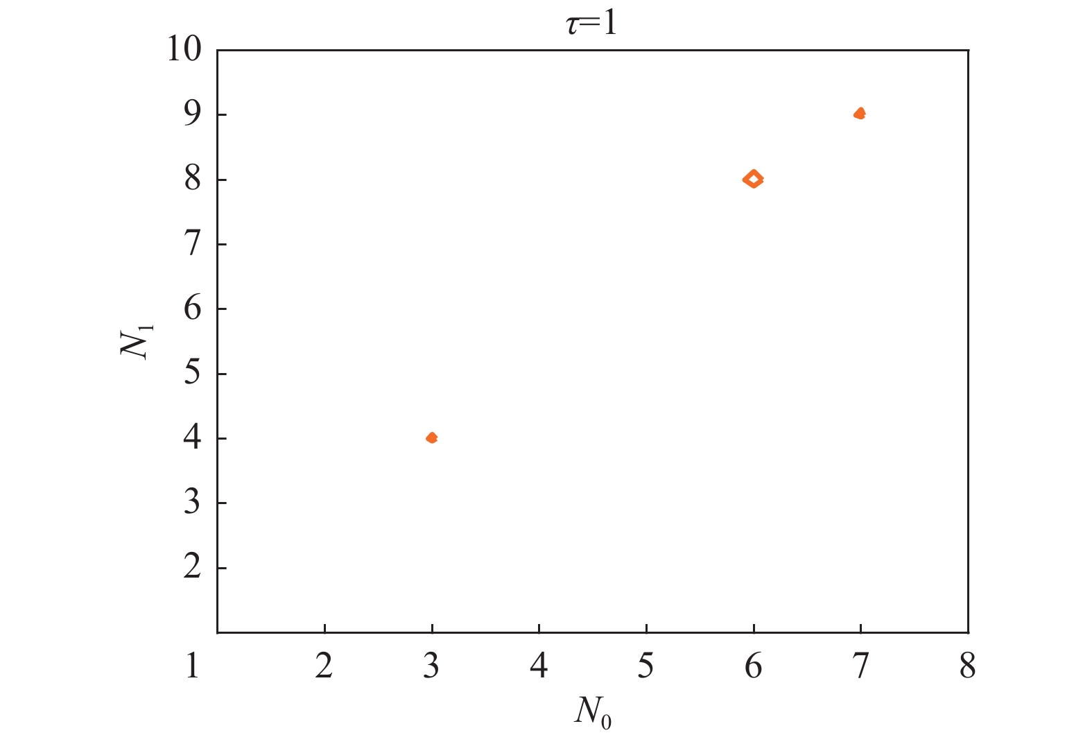
      Figure 9.  Distribution of magnetic field uniformity error

      $$ \sigma {{ = }}\frac{{\eta {{ - }}{\eta _0}}}{{{\eta _0}}} \times 100{\text{% }} $$ (4)

      在误差为1的前提下,通过相同的方法获得了2.1 m/0.5 m/0.5 T的最小整数圈数N0=7、N1=9和I=92.0 kA,N0=3、N1=5和I=97.5 kA。

      根据上述线圈结构参数和线圈产生磁场的能力,可以估算不同最小试验磁场下的总线圈重量和总线圈功率损耗。总重量G3和总功率损失P3可表示为

      $$ \left\{ \begin{gathered} {G_3} = \rho {V_3} = \frac{\rho }{J} \cdot 4{a_3} \cdot {M_3}{\text{ = }}\frac{\rho }{J} \cdot 4{a_3} \cdot ({N_0} + 2{N_1})I \\ {P_3} = \frac{{{J^2}{V_3}}}{\sigma } = \frac{J}{\sigma } \cdot 4{a_3} \cdot {M_3}{\text{ = }}\frac{J}{\sigma } \cdot 4{a_3} \cdot ({N_0} + 2{N_1})I \\ \end{gathered} \right. $$ (5)

      式中:

      ρ —— 导体质量密度(kg/m3);

      J —— 导体电流密度,J=4 A/mm2

      σ —— 导体电导率(S/m);

      V3—— 总体积(m3)。

      采用既有400 mm×60 mm铝母线,层间绝缘10 mm。

      通过计算得到线圈参数,如表3所示。

      类型2.1 m/0.5 T1 m/0.5 T
      导体截面/mm2400×60400×60
      匝数9/7/95/3/5
      绝缘距离/mm1010
      横向尺寸2.778 m/3.578 m1.364 m/2.164 m
      纵向尺寸/m3.1202.047
      总重量/t19.76.1 t
      电流/ kA92.097.5
      电感/mH5.270.983
      电阻/mΩ0.4190.128
      功耗/MW3.5441.084

      Table 3.  Basic parameters of square three-coil

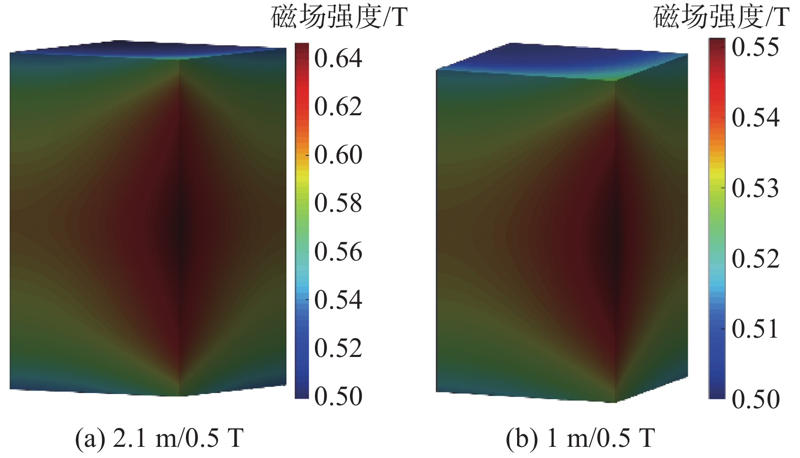
      基于上述参数,建立图10所示的仿真模型,以计算磁场分布,如图11所示。对于2.1 m/0.5 T,最小磁场为500.0 mT,最大值为651.7 mT,磁场均匀性为1.303。对于1 m/0.5 T,最小磁场为500.0 mT,最大磁场为553.4 mT,磁场均匀性为1.107。方形螺线管线圈功耗2.981 MW (2.1 m/0.5 T)和0.651 MW (1 m/0.5 T),对比三线圈结构3.544 MW (2.1 m/0.5 T)和1.084 MW (1 m/0.5 T)在功耗方面更占优势。选择方形螺线管作为最终结构。

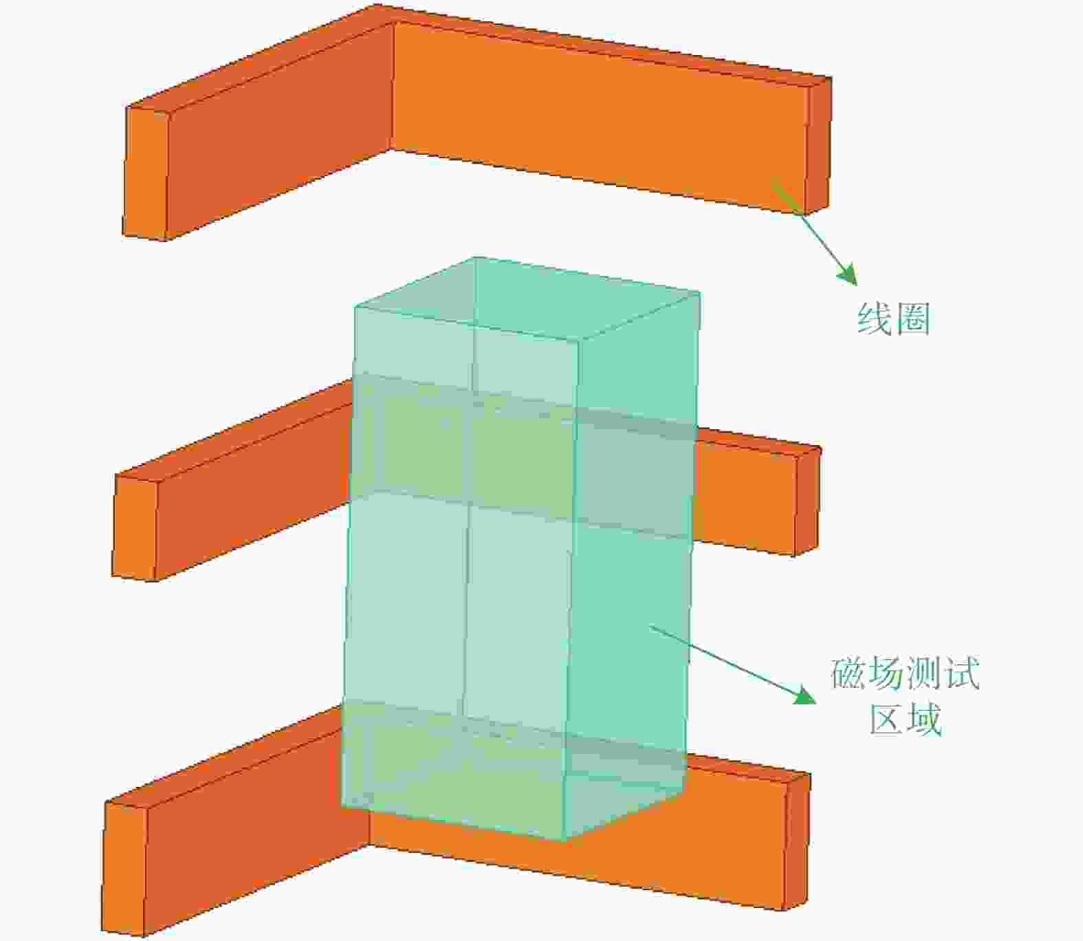
      Figure 10.  1/4 model of the three-coil

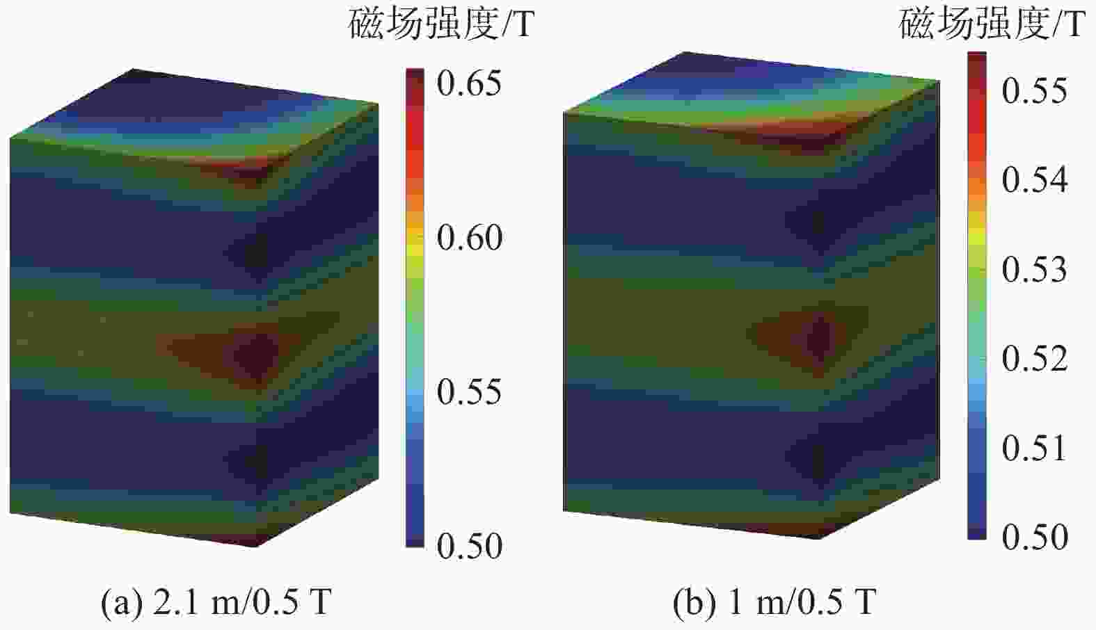
      Figure 11.  Magnetic field distribution (1/4) of the three coils in the test area

    • 在直流稳态磁场试验中,要求直流电源系统为线圈系统提供稳定可控的直流电流,即需要提供45 kA (2.1 m/0.5 T)和35.6 kA (1 m/0.5 T)两种电流,可使用ITER现有的直流电源测试平台提供,可输出±55 kA、±1 050 V的电源,设备参数如表4所示,可以看出其输出足以满足需求。

      参数
      容量/MVA82
      电压66 kV/1.0 kV
      短路阻抗16%±7.5%+1%
      输出电流/kA±55
      输出电压/kA±1.05

      Table 4.  Equipment parameters of DC power test platform for ITER

    • 基于图3所示的电路拓扑,假设峰值充电电流为I0,无论换向时间如何,线圈电流可以表示为:

      $$ \left\{ \begin{gathered} {i_L} = {I_0}{{\rm{e}}^{ - t/\delta }} \\ \tau {\text{ = }}\frac{L}{{R{\text{ + }}{R_0}}} \\ \end{gathered} \right. $$ (6)

      如果线圈的磁场产生效率定义为K,则相应的磁场变化率为:

      $$ \frac{{{\rm{d}}B}}{{{\rm{d}}t}} = K\frac{{{\rm{d}}{i_L}}}{{{\rm{d}}t}} = - \frac{{K{I_0}\left( {R + {R_0}} \right)}}{L}{{\rm{e}}^{ - {t \mathord{\left/ {\vphantom {t \tau }} \right. } \tau }}} $$ (7)

      磁场变化率要求在14 T/s到30 T/s之间;也就是说,最大磁场变化率为30 T/s。

      $$ \frac{{K{I_0}\left( {R + {R_0}} \right)}}{L}{\text{ = }}30\;{{\rm{T}} \mathord{\left/ {\vphantom {{\rm{T}} {\rm{s}}}} \right. } {\rm{s}}} $$ (8)

      如果要求磁场变化率在14 T/s和30 T/s之间保持50 ms,则:

      $$ 30{{\rm{e}}^{ - {{50} \mathord{\left/ {\vphantom {{50} \tau }} \right. } \tau }}}{\text{ = }}14 \Rightarrow \tau {\text{ = }}\frac{L}{{R + {R_0}}} = 65.6\;{{\rm{ms}}} $$ (9)

      1) 2.1 m/0.5 T线圈

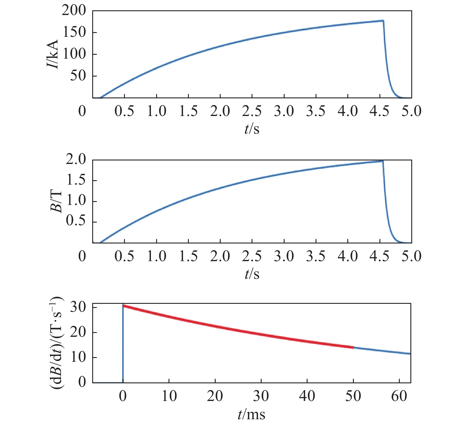
      对于2.1 m/0.5 T线圈,可计算L=5.27 mH、R=1.47 mΩ和R0=79 mΩ。对于该线圈,其磁场产生效率为K=11.1 mT/kA,I0=177.3 kA,假设能量放电电阻的温升上限设置为80 °C,并采用不锈钢电阻,则相应的线圈储能为82.83 MJ,相应的重量约为2.25 t。试验期间的放电电流波形如图12所示(假设变流器的输出电压为500 V)。

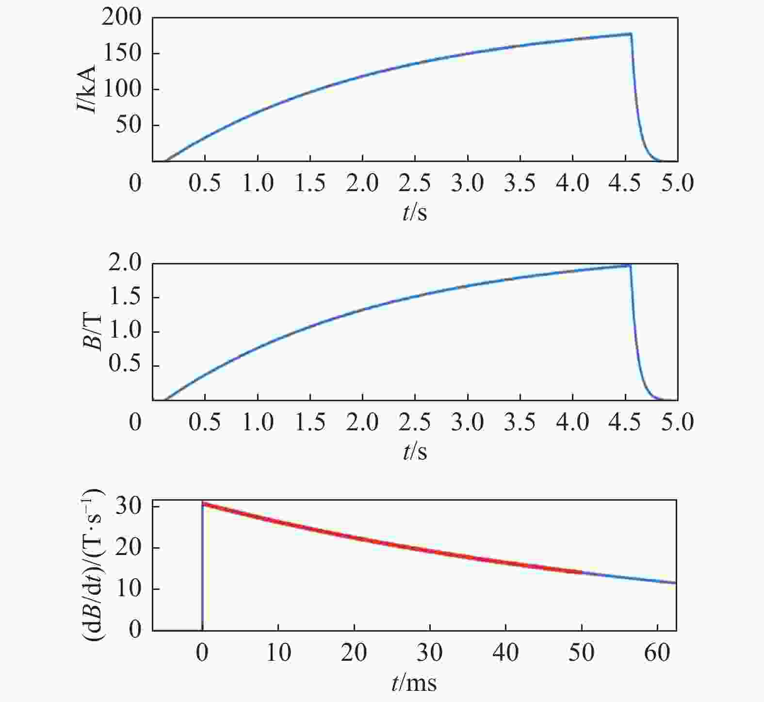
      Figure 12.  Waveform diagram of the coil current, magnetic field and change rate of 2.1 m/0.5

      2) 1 m/0.5 T线圈

      对于1 m/0.5 T线圈,可计算L=0.983 mH、R=0.514 mΩ和R0=14.5 mΩ。对于该线圈,其磁场产生效率为K=14 mT/kA,I0=140.6 kA,相应的线圈储能为9.72 MJ,相应的重量约为0.26 t。试验期间的放电电流波形如图13所示。

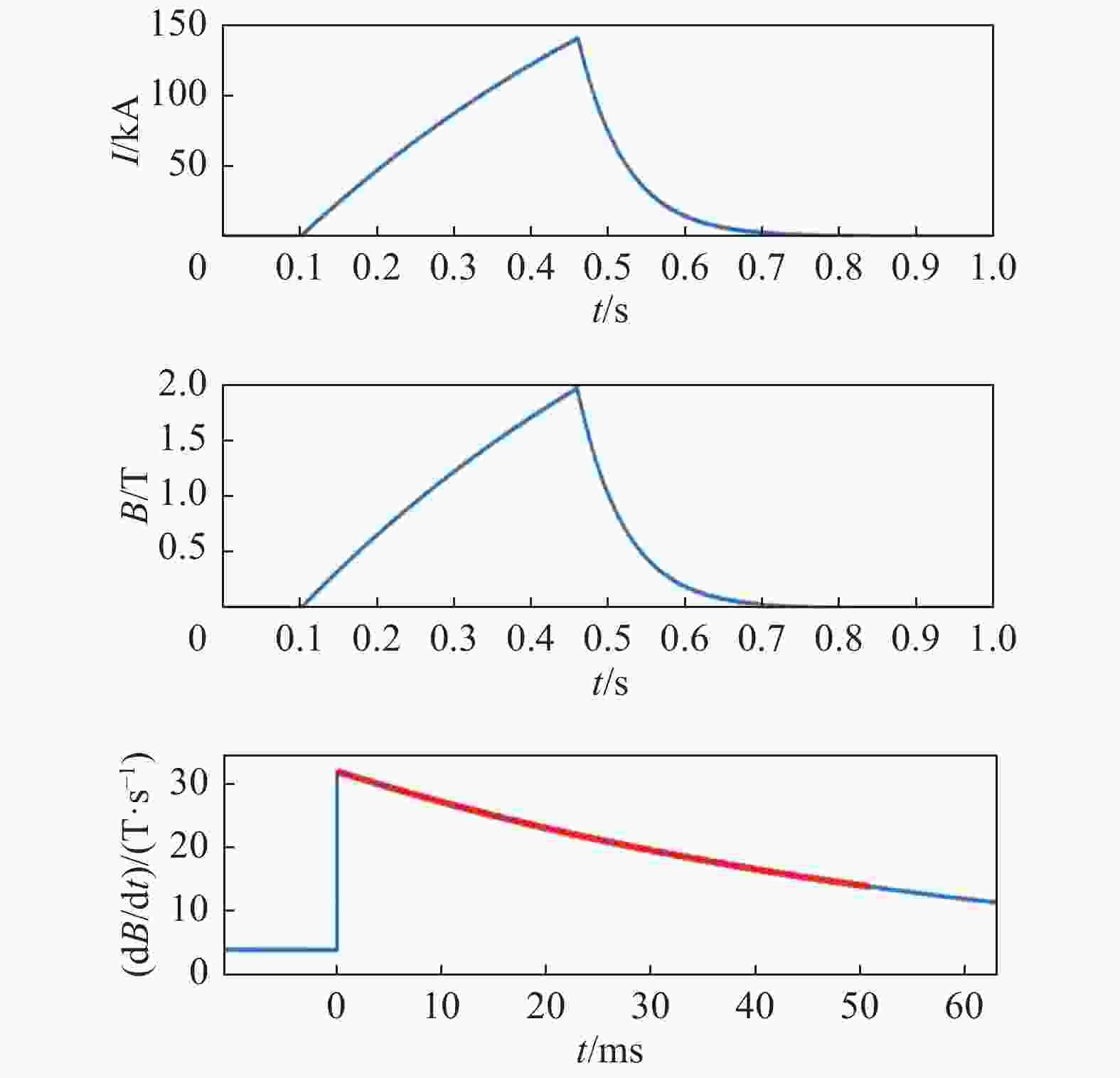
      Figure 13.  Waveform diagram of the coil current, magnetic field and change rate of 1 m/0.5

      最终的方案如表5所示。

      类型直流稳态直流瞬态
      测试需求0.5 T14~30 T/s (>50 ms)
      2.1 m/0.5 T45.0 kA/2.981 MW82.83 MJ/79 mΩ
      1 m/0.5 T35.6 kA/0.651 MW9.72 MJ/14.5 mΩ

      Table 5.  Power scheme

    • 聚变装置ITER相关电气电子设备所需的磁场抗扰度测试系统,分析和设计了方形螺线管线圈系统和方形三线圈系统,并提出相应的了直流电源功率/电流的参数。根据ITER组织针对设备体积的要求,设计了2.1 m/0.5 T和1 m/0.5 T线圈结构,使用解析法和有限元法计算了最佳结构参数,并对其磁场性能进行了比较分析。确定了功耗较小的方形螺线管为最终结构。同时,分析了直流暂态的功率拓扑,计算了相关参数,为实际制造提供了理论依据。

Reference (21)

Catalog

    /

    DownLoad:  Full-Size Img  PowerPoint
    Return
    Return