• Peer Review
  • Non-profit
  • Global Open Access
  • Green Channel for Rising Stars
Volume 9 Issue S2
Jan.  2023
Turn off MathJax
Article Contents

LIN Wangyong, CHEN Yin, ZHANG Hua. Wind-Induced Response Analysis of 1 000 kV Lattice Independent Lightning Protection Tower[J]. SOUTHERN ENERGY CONSTRUCTION, 2022, 9(S2): 68-73. doi: 10.16516/j.gedi.issn2095-8676.2022.S2.011
Citation: LIN Wangyong, CHEN Yin, ZHANG Hua. Wind-Induced Response Analysis of 1 000 kV Lattice Independent Lightning Protection Tower[J]. SOUTHERN ENERGY CONSTRUCTION, 2022, 9(S2): 68-73. doi: 10.16516/j.gedi.issn2095-8676.2022.S2.011

Wind-Induced Response Analysis of 1 000 kV Lattice Independent Lightning Protection Tower

doi: 10.16516/j.gedi.issn2095-8676.2022.S2.011
  • Received Date: 2021-11-24
    Available Online: 2023-01-04
  • Publish Date: 2023-01-04
  •   Introduction  This paper is aimed to study the wind-induced response of 1000 kV lattice independent lightning protection tower and propose the reasonable value of wind-induced vibration coefficient.   Method  The wind-induced response of 1000 kV lattice lightning protection tower was analyzed in this paper with the help of finite element software ANSYS based on the Davenport fluctuating wind speed power spectral density function adopted in the Load Code for Building Structures and the structural random vibration theory and frequency domain analysis method. The wind-induced vibration coefficient was compared with that calculated by the simplified formula recommended in the Standard for Design of High-Rising Structures.   Result  The analysis results show that the overall deformation of the lightning protection tower meets the specification requirements for the class B landform when the basic wind pressure is not greater than 0.60 kN/m2; The wind vibration coefficient value obtained from the simplified formula recommended in the Standard for Design of High-Rising Structures and the recommended value in the Technical Code for the Design of Substation Buildings and Structures are generally smaller than the value obtained from the finite element analysis, so special attention should be paid to it during structural design.   Conclusion  According to the comparative analysis results of this paper, it is recommended that the wind-induced vibration coefficient can be uniformly taken as 2.20 during the structural design of 1000 kV lattice independent lightning protection tower.
  • [1] 陈寅, 陈传新, 张华, 等. 换流站避雷线塔风振系数计算 [J]. 电网与清洁能源, 2011, 27(8): 50-52. DOI:  10.3969/j.issn.1674-3814.2011.08.010.

    CHEN Y, CHEN C X, ZHANG H, et al. Wind vibration coefficient calculation of lightning protection tower in converter station [J]. Advances of Power System and Hydroelectric Engineering, 2011, 27(8): 50-52. DOI:  10.3969/j.issn.1674-3814.2011.08.010.
    [2] 李正良, 罗熙越, 蔡青青. 考虑塔-线耦合作用的输电塔体系风振系数研究 [J]. 建筑钢结构进展, 2021, 23(3): 119-128. DOI:  10.13969/j.cnki.cn31-1893.2021.03.013.

    LI Z L, LUO X Y, CAI Q Q. A study on the wind vibration coefficient of transmission tower system considering tower-line coupling effect [J]. Progress in Steel Building Structures, 2021, 23(3): 119-128. DOI:  10.13969/j.cnki.cn31-1893.2021.03.013.
    [3] 原迁, 张德凯. 大跨越输电塔线体系风振响应及风振系数分析 [J]. 山西建筑, 2021, 47(6): 34-38. DOI:  10.3969/j.issn.1009-6825.2021.06.012.

    YUAN Q, ZHANG D K. Analysis of wind-induced response and vibration coefficient of long-span transmission line tower [J]. Shanxi Architecture, 2021, 47(6): 34-38. DOI:  10.3969/j.issn.1009-6825.2021.06.012.
    [4] 窦汉岭, 程长征. 转角输电塔线体系的风振响应分析 [J]. 合肥工业大学学报(自然科学版), 2020, 43(9): 1218-1222. DOI:  10.3969/j.issn.1003-5060.2020.09.013.

    DOU H L, CHENG C Z. Analysis on wind-induced response of corner transmission tower-line system [J]. Journal of Hefei University of Technology (Natural Science Edition), 2020, 43(9): 1218-1222. DOI:  10.3969/j.issn.1003-5060.2020.09.013.
    [5] 邓洪洲, 张建明, 帅群, 等. 输电钢管塔体型系数风洞试验研究 [J]. 电网技术, 2010, 34(9): 190-194. DOI:  10.13335/j.1000-3673.pst.2010.09.024.

    DENG H Z, ZHANG J M, SHUAI Q, et al. Wind-tunnel investigation on pressure coefficient of steel tubular transmission tower [J]. Power System Technology, 2010, 34(9): 190-194. DOI:  10.13335/j.1000-3673.pst.2010.09.024.
    [6] 邹良浩, 梁枢果, 邹垚, 等. 格构式塔架风载体型系数的风洞试验研究 [J]. 特种结构, 2008, 25(5): 41-43,68. DOI:  10.3969/j.issn.1001-3598.2008.05.013.

    ZOU L H, LIANG S G, ZOU Y, et al. Investigation on wind load shape coefficient of lattice towers by wind tunnel tests [J]. Special Structures, 2008, 25(5): 41-43,68. DOI:  10.3969/j.issn.1001-3598.2008.05.013.
    [7] 沈国辉, 项国通, 郭勇, 等. 圆钢输电塔架的风荷载体型系数研究 [J]. 特种结构, 2015, 32(5): 62-65,85.

    SHEN G H, XIANG G T, GUO Y, et al. Research on body shape coefficients of wind loads on steel transmission towers with cylindrical members [J]. Special Structures, 2015, 32(5): 62-65,85.
    [8] 林汪勇, 陈寅, 杨彪. 1000 kV变电构架位移风振系数研究 [J]. 低温建筑技术, 2013, 35(4): 75-76. DOI:  10.3969/j.issn.1001-6864.2013.04.030.

    LIN W Y, CHEN Y, YANG B. Wind displacement vibration coefficient research of 1 000 kV truss structures [J]. Low Temperature Architecture Technology, 2013, 35(4): 75-76. DOI:  10.3969/j.issn.1001-6864.2013.04.030.
    [9] 中华人民共和国住房和城乡建设部. 建筑结构荷载规范: GB 50009—2012 [S]. 北京: 中国建筑工业出版社, 2012.

    Ministry of Housing and Urban-Rural Development of the People's Republic of China. Load code for the design of building structures: GB 50009—2012 [S]. Beijing: China Architecture & Building Press, 2012.
    [10] 祝曦晨. 输电塔架及输电塔线体系等效静力风荷载研究 [D]. 武汉: 武汉大学, 2017.

    ZHU X C. Investigation on equivalent static wind load of lattice towers and transmission tower-line system [D]. Wuhan: Wuhan University, 2017.
    [11] 张相庭. 结构风工程: 理论·规范·实践 [M]. 北京: 中国建筑工业出版社, 2006.

    ZHANG X T. Structural wind engineering: Theory·Standard·Practice [M]. Beijing: China Architecture & Building Press, 2006.
    [12] 国家能源局. 变电站建筑结构设计技术规程: DL/T 5457—2012 [S]. 北京: 中国电力出版社, 2012.

    National Energy Administration. Technical code for the design of substation buildings and structures: DL/T5457—2012 [S]. Beijing: China Electric Power Press, 2012.
    [13] 中华人民共和国住房和城乡建设部, 国家市场监督管理总局. 高耸结构设计标准: GB 50135—2019 [S]. 北京: 中国计划出版社, 2019.

    Ministry of Housing and Urban-Rural Development of the People's Republic of China, State Administration for Market Regulation. Standard for design of high-rising structures: GB 50135—2019 [S]. Beijing: China Planning Press, 2019.
  • 通讯作者: 陈斌, bchen63@163.com
    • 1. 

      沈阳化工大学材料科学与工程学院 沈阳 110142

    1. 本站搜索
    2. 百度学术搜索
    3. 万方数据库搜索
    4. CNKI搜索

Figures(1)  / Tables(6)

Article Metrics

Article views(67) PDF downloads(55) Cited by()

Related

Wind-Induced Response Analysis of 1 000 kV Lattice Independent Lightning Protection Tower

doi: 10.16516/j.gedi.issn2095-8676.2022.S2.011

Abstract:   Introduction  This paper is aimed to study the wind-induced response of 1000 kV lattice independent lightning protection tower and propose the reasonable value of wind-induced vibration coefficient.   Method  The wind-induced response of 1000 kV lattice lightning protection tower was analyzed in this paper with the help of finite element software ANSYS based on the Davenport fluctuating wind speed power spectral density function adopted in the Load Code for Building Structures and the structural random vibration theory and frequency domain analysis method. The wind-induced vibration coefficient was compared with that calculated by the simplified formula recommended in the Standard for Design of High-Rising Structures.   Result  The analysis results show that the overall deformation of the lightning protection tower meets the specification requirements for the class B landform when the basic wind pressure is not greater than 0.60 kN/m2; The wind vibration coefficient value obtained from the simplified formula recommended in the Standard for Design of High-Rising Structures and the recommended value in the Technical Code for the Design of Substation Buildings and Structures are generally smaller than the value obtained from the finite element analysis, so special attention should be paid to it during structural design.   Conclusion  According to the comparative analysis results of this paper, it is recommended that the wind-induced vibration coefficient can be uniformly taken as 2.20 during the structural design of 1000 kV lattice independent lightning protection tower.

LIN Wangyong, CHEN Yin, ZHANG Hua. Wind-Induced Response Analysis of 1 000 kV Lattice Independent Lightning Protection Tower[J]. SOUTHERN ENERGY CONSTRUCTION, 2022, 9(S2): 68-73. doi: 10.16516/j.gedi.issn2095-8676.2022.S2.011
Citation: LIN Wangyong, CHEN Yin, ZHANG Hua. Wind-Induced Response Analysis of 1 000 kV Lattice Independent Lightning Protection Tower[J]. SOUTHERN ENERGY CONSTRUCTION, 2022, 9(S2): 68-73. doi: 10.16516/j.gedi.issn2095-8676.2022.S2.011
    • 格构式避雷线塔目前被广泛地应用于变电站以及换流站当中,这类结构一般具有轻质、高柔的特点。随着电压等级的升高,避雷线塔的高度也随之不断增大,同时随着结构高度的增大此类结构的刚度和阻尼进一步降低,从而增加了其对风的敏感性,同时风荷载是此类构筑物结构设计的主要控制荷载。目前1 000 kV避雷线塔最大高度为60 m,具有轻质、高柔、小阻尼等特性,使得1 000 kV格构式独立避雷线塔在强风的作用下会产生较大幅度的位移和振动,其风致振动和动力特征分析已成为变电站、换流站结构设计长期关注的重要内容。

      国内外专门对避雷线塔风致响应的相关理论分析与试验研究相对较少,相关设计均为根据规范方法计算得到或者参考输电塔、变电构架相关理论和试验研究成果。陈寅等[1]根据3种不同的设计规范,对换流站4种不同形式避雷塔架进行风振系数计算,通过分析比较,得出避雷线塔风振系数的计算方法和取值标准;李正良等[2]以某220 kV塔线体系为原型,通过气弹性风洞试验和有限元数值模拟的方式,计算该输电塔的风振系数,并与我国现行规范中的相关取值进行对比;原迁等[3]以智利CHACAO大跨越工程为例,在ANSYS中建立塔线体系有限元模型,从结构的动力特性和风振响应几个方面对单塔及塔线体系进行风振分析;并根据时程分析结果对风振系数进行计算并和规范结果对比。窦汉岭等[4]以某220 kV的输电线路为工程背景,利用ANSYS软件建立了转角输电塔线耦联体系的有限元模型,通过模态分析研究了模型的动力特性,采用谐波合成法在模拟出风荷载,并对转角输电塔线体系的风振响应进行时程分析;邓洪州等[5]针对1 000 kV特高压输电线路钢管塔进行了高频测力天平风洞试验,得到了作用在模型上的平均风荷载和体型系数;邹良浩等[6]利用高频测力天平风洞试验分别得到了3种典型的角钢格构式塔架的基底弯矩、基底剪力时程,在此基础上提出了格构式塔架的风载体型系数取值方法,进而计算出上述格构式塔架在不同工况下的风载体型系数;沈国辉等[7]在B类地貌中进行4个塔架模型的天平测力风洞试验,计算塔架在XY方向的体型系数,探讨体型系数随风向角的分布特征,并将试验结果与国内外规范进行比较;林汪勇等[8]以1 000 kV变电构架为背景,基于随机振动理论通过有限元软件计算得到其位移风振系数,并与标准方法所得风振系数进行比较。

      本文在上述研究的基础上,采用有限元软件ANSYS,基于随机振动理论,以某实际1 000 kV变电站格构式独立避雷线为原型,对1 000 kV格构式独立避雷线进行风致响应有限元分析。

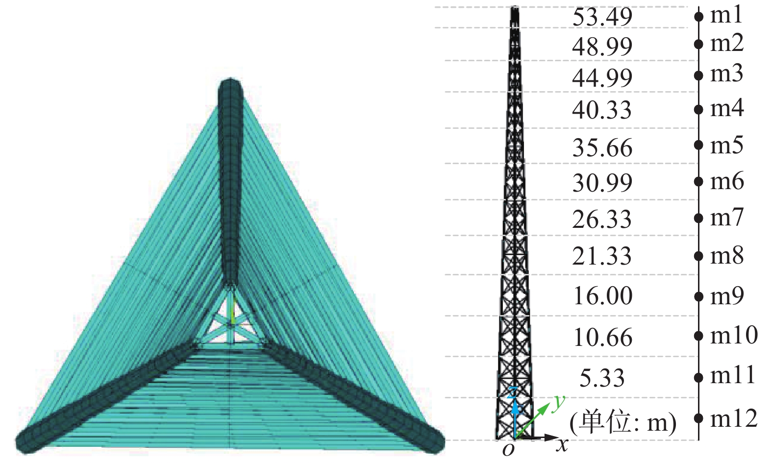
    • 本文所研究的1 000 kV格构式独立避雷线塔截面型式为三角形,高度为60 m,弦杆采用圆钢、腹杆采用角钢,其截面尺寸自下而上递减,所处地区为B类地貌,100年一遇基本风压w0=0.60 kN/m2

      采用通用有限元分析软件ANSYS建立1 000 kV格构式独立避雷线塔的有限元模型,结构阻尼比取0.02。模型假定所有杆件为铰接,采用三维梁单元(BEAM188)模拟各杆件,为便于分析相关数据,将60 m高1 000 kV格构式独立避雷线塔分为12层,有限元分析模型见图1。模型经模态分析后得到模型的前6阶频率见表1

      Figure 1.  Finite element model of 1000 kV lattice lightning rod

      频率阶次避雷针频率/Hz振型
      11.2413一阶横向弯曲
      21.2413一阶纵向弯曲
      34.6223二阶横向弯曲
      44.6223二阶纵向弯曲
      510.1630三阶纵向弯曲
      610.1630三阶横向弯曲

      Table 1.  First three order natural frequencies

    • 按照《建筑结构荷载规范》[9],对于1 000 kV格构式独立避雷线塔而言,其各层高度处的平均风荷载可按照下式来计算:

      $$ {\bar P_{\left( {\textit{z}} \right)}} = {\mu _{s({\textit{z}})}}{\mu _{{\textit{z}}({\textit{z}})}}{w_0}{S_{\left( {\textit{z}} \right)}}{R_{\left( {\textit{z}} \right)}}$$ (1)

      式中:

      $\bar P_\left( {\textit{z}} \right)$ ——避雷针高度z(m)处平均风荷载(kN);

      μs(z) ——避雷针结构各层高度处体型系数;

      μz(z) ——避雷针各层高度处风压变化系数;

      $ {w_0} $ ——基本风压(kN/m2);

      S(z) ——避雷针架各层高度处轮廓面积(m2);

      R(z) ——避雷针架各层高度处挡风系数。

    • 根据我国《建筑结构荷载规范》[9]中采用加拿大学者Davenport提出的顺风向脉动风速功率谱密度函数,本文采用该功率谱密度函数来推导脉动风荷载功率谱密度函数,顺风向脉动风速功率谱密度函数表达式为:

      $$ {S_{v(n)}} = \frac{{4K{{\overline V }_{10}}^2{x^2}}}{{n{{(1 + {x^2})}^{\frac{4}{3}}}}} $$ (2)

      式中:

      Sv(n) ——脉动风速谱(m/s);

      K ——与地貌相关的表面阻力系数;

      ${\overline V _{10}}$ ——10 m高度处的平均风速(m/s);

      n ——脉动风频率(Hz);

      $$ x = \frac{{1\;200{n}}}{{{{\overline V }_{10}}}} $$ (3)

      将1 000 kV格构式独立避雷线塔沿高划分成12段,结合随机振动理论,同时结合参考文献[10]以及文献[11],可得第i段脉动风荷载谱计算式如下:

      $$ {S_{{\rm{P}}i(n)}} = {[\sqrt {24K} \mu _{{\textit{z}}i({\textit{z}})}^{0.5}{\mu _{{\rm{s}}i({\textit{z}})}}{w_0}{A_i}]^2}{S_{{\rm{f}}(n)}}{{\rm{coh}}_{(i,j)}} $$ (4)
      $$ {S_{\rm{f}}(n)} = \frac{{2x_{}^2}}{{3n{{(1 + x_{}^2)}^{4/3}}}} $$ (5)

      式中:

      ${\mu _{{{\rm{s}}i}(z)}}$ ——第i段的体形系数;

      ${\mu _{{zi}(z)}}$ ——风压沿高度变化系数;

      $ {A_i} $ ——第i段迎风面面积(m2);

      $ {w_0} $ ——基本风压(kN/m2);

      ${\text{coh}}_{(i,j)}$ ——ij两点的互相关函数,相关参数取值见表2

      层数体型系数${\mu _{{\rm{s}}i}}$迎风面面积/m2挡风系数R
      m11.601.840.79
      m21.624.190.49
      m31.764.710.42
      m41.866.670.37
      m51.907.920.35
      m61.999.180.30
      m71.9510.440.33
      m82.0012.580.30
      m92.0915.020.26
      m102.0216.650.29
      m112.0518.300.27
      m122.1319.940.24

      Table 2.  Structural parameters of lightning protection tower

      将式(4)计算所得脉动风荷载谱输入通用有限元分析软件ANSYS进行功率谱分析,经计算可得1 000 kV格构式独立避雷线塔第i段的位移响应根方差,进而得到构架第i段位移风振系数,即总位移与平均风压位移的比值,具体见式(6)。

      $$ {\beta _{{\text{u}}(x)}} = \frac{u}{{\bar{u}}} = 1 + \frac{{\mu {\sigma _{u}}}}{{\overline {u} }} $$ (6)

      式中:

      μ——峰值因子,根据《建筑结构荷载规范》取2.5。

    • 表3表4显示了1 000 kV格构式独立避雷线塔位移响应以及风振系数沿高分布规律。由表3表4可以看出:(1)1 000 kV格构式独立避雷线塔平均位移、均方根位移、合位移以及风振系数沿高整体均呈增大趋势;(2)X向风振系数最大值为1.84,加权平均值为1.82,最大合位移为244 mm,相对变形值为1/246;(3)Y向风振系数最大值为2.18,加权平均值为2.06,最大合位移为331 mm,相对变形值为1/181;(4)XY向相对变形值均满足《变电站建筑结构设计技术规程》[12]对格构式避雷线塔相对变形值为1/100的要求。

      层数平均位移/m均方根位移/m合位移/m风振系数
      m11.33E-014.46E-022.44E-011.84
      m21.17E-013.91E-022.15E-011.83
      m31.01E-013.36E-021.85E-011.83
      m48.41E-022.81E-021.54E-011.84
      m56.73E-022.24E-021.23E-011.83
      m65.21E-021.73E-029.53E-021.83
      m73.88E-021.28E-027.08E-021.82
      m82.73E-028.98E-034.98E-021.82
      m91.66E-025.42E-033.01E-021.82
      m108.61E-032.78E-031.56E-021.81
      m113.24E-031.04E-035.83E-031.80
      m123.69E-041.13E-046.51E-041.76
      风振系数加权平均值1.82

      Table 3.  X-direction displacement response and wind-induced vibration coefficient

      层数平均位移/m均方根位移/m合位移/m风振系数
      11.52E-017.16E-023.31E-012.18
      21.35E-016.28E-022.92E-012.16
      31.18E-015.39E-022.52E-012.15
      49.91E-024.51E-022.12E-012.14
      58.04E-023.59E-021.70E-012.12
      66.32E-022.77E-021.33E-012.10
      74.78E-022.05E-029.92E-022.07
      83.43E-021.44E-027.03E-022.05
      92.13E-028.70E-034.30E-022.02
      101.13E-024.47E-032.25E-021.99
      114.41E-031.67E-038.58E-031.94
      125.56E-041.81E-041.01E-031.82
      风振系数加权平均值2.06

      Table 4.  Y-direction displacement response and wind-induced vibration coefficient

    • 根据《高耸结构设计标准》[13]自立式高耸结构在z高度处的风振系数${\beta _{z}}$可按式(6)确定:

      $$ {\beta _{z}} = 1 + \xi {\varepsilon _1}{\varepsilon _2} $$ (7)

      式中:

      $\xi $ ——脉动增大系数;

      ${\varepsilon _1}$——风压脉动和风压高度变化等影响系数;

      ${\varepsilon _2}$——振型、结构外形的影响系数。

      表5表6中列出1 000 kV格构式独立避雷线塔采用《高耸结构设计标准》推荐的简化公式所得以及有限元分析所得风振系数的值以及两者间的相对误差。

      层数有限元分析所得
      风振系数
      标准方法所得
      风振系数
      误差
      11.841.924.17%
      21.831.956.15%
      31.831.945.67%
      41.841.903.16%
      51.831.851.08%
      61.831.71−7.02%
      71.821.59−14.47%
      81.821.46−24.66%
      91.821.33−36.84%
      101.811.18−53.39%
      111.801.08−66.67%
      121.761.02−72.55%
      加权平均值1.821.55−17.42%

      Table 5.  Comparison of X-direction wind-induced vibration coefficients

      层数有限元分析所得
      风振系数
      标准方法所得
      风振系数
      误差
      12.181.92−13.54%
      22.161.95−10.77%
      32.151.94−10.82%
      42.141.90−12.63%
      52.121.85−14.59%
      62.101.71−22.81%
      72.071.59−30.19%
      82.051.46−40.41%
      92.021.33−51.88%
      101.991.18−68.64%
      111.941.08−79.63%
      121.821.02−78.43%
      加权平均值2.061.55−32.90%

      Table 6.  Comparison of Y-direction wind-induced vibration coefficients

      通过对比两种方法所得风振系数的大小以及变化规律可知:与有限元分析所得风振系数变化规律类似,标准方法所得风振系数值为顶部最大,中间其次,底部最小。标准方法所得值,除X向风振系数顶部区域大于本文计算所得风振系数值外,X向其他区域以及Y向风振系数均小于本文计算所得风振系数值。顶部区域最大相差13.54%,中部区域最大相差40.41%,底部区域最大相差78.43%,但底部区域风荷载较小对整体受力影响不明显。两者沿高加权平均值,X向相差17.4%,Y向相差32.9%,标准方法计算所得风振系数最大值为1.95,沿高加权平均值为1.55。

      总体而言,《高耸结构设计标准》推荐的简化公式所得风振系数计算值比有限元分析所得值小,因为标准公式基本计算理论仍是基于第一振型的惯性风荷载法,计算时仅考虑一阶振型系数,对于类似1 000 kV格构式独立避雷线塔这类高耸结构在进行风振计算时,其高阶振型和扭转振型的贡献所占比例是不可忽略的。

      综合比较标准所得以及有限元分析所得风振系数值,按《高耸结构设计标准》推荐公式计算所得向风振系数高加权平均值为1.55与《变电站建筑结构设计技术规程》所取1.5比较接近,均小于有限元分析所得风振系数值,偏于不安全,对于1 000 kV格构式独立避雷线塔这类风荷载为控制荷载的高耸结构,在设计时应特别注意。同时根据本文的对比分析结果,推荐1 000 kV格构式独立避雷线塔结构设计时,风振系数可统一取2.20,进行包络设计。

    • 本文以1 000 kV格构式独立避雷线塔为研究对象,借助有限元软件ANSYS,基于结构随机振动理论以及频域分析方法,分析了B类地貌下,该类型避雷线塔的风致响应,并与规范方法所得风振系数值进行对比,得出的主要结论如下:

      1)基本风压不大于w0=0.60 kN/m2时,该避雷线塔总体变形满足《变电站建筑结构设计技术规程》对格构式避雷线塔相对变形值为1/100的要求。

      2)对于1 000 kV格构式独立避雷线塔进行风振计算时仅考虑一阶振型系数,误差相对较大,应考虑高阶振型和扭转振型的影响。

      3)在1 000 kV格构式独立避雷线塔结构设计时,风振系数可统一取2.20,进行包络设计。

      4)《高耸结构设计标准》推荐方法所得风振系数值以及《变电站建筑结构设计技术规程》的推荐值均小于本文限元分析所得值,偏于不安全,结构设计时应特别注意。

Reference (13)

Catalog

    /

    DownLoad:  Full-Size Img  PowerPoint
    Return
    Return