• Peer Review
  • Non-profit
  • Global Open Access
  • Green Channel for Rising Stars
Volume 9 Issue S2
Jan.  2023
Turn off MathJax
Article Contents

DONG Yi, SI Huaning, ZHONG Yuwei, LI Ning, XU Huiping. Research on DC Microgrid Control Using Microcontroller to Realize Constant Voltage or Constant Current Variable Load[J]. SOUTHERN ENERGY CONSTRUCTION, 2022, 9(S2): 84-89. doi: 10.16516/j.gedi.issn2095-8676.2022.S2.014
Citation: DONG Yi, SI Huaning, ZHONG Yuwei, LI Ning, XU Huiping. Research on DC Microgrid Control Using Microcontroller to Realize Constant Voltage or Constant Current Variable Load[J]. SOUTHERN ENERGY CONSTRUCTION, 2022, 9(S2): 84-89. doi: 10.16516/j.gedi.issn2095-8676.2022.S2.014

Research on DC Microgrid Control Using Microcontroller to Realize Constant Voltage or Constant Current Variable Load

doi: 10.16516/j.gedi.issn2095-8676.2022.S2.014
  • Received Date: 2022-05-28
  • Rev Recd Date: 2022-10-21
  • Available Online: 2023-01-04
  • Publish Date: 2023-01-04
  •   Introduction  The paper aims to realize constant voltage or constant current microgrid control under different types of load conditions.   Method  A simple DC microgrid was built by using a microcontroller and other circuit components, a closed-loop PID controller was used to control the circuit, and a Simulink simulation model was built at the same time, and the PID parameters were designed and simulated in advance using the simulation model. It could make the PID parameter setting reasonable, reduced the hidden danger of hardware in the microgrid, and ensured the normal operation of each part of the circuit in the process of hardware construction.   Result  It can be seen from the experimental data that the output value error can be guaranteed to be less than 2% in terms of constant voltage or constant current output.   Conclusion  The feasibility of using a microcontroller to control the voltage and current of the microgrid is demonstrated in this paper.
  • [1] 陈洪涛. 直流微电网母线电压稳定性控制策略研究 [D]. 淄博: 山东理工大学, 2019. DOI: 10.27276/d.cnki.gsdgc.2019.000083.

    CHEN H T. Stability control strategy of bus voltage for DC microgrid [D]. Zibo: Shandong University of Technology, 2019. DOI: 10.27276/d.cnki.gsdgc.2019.000083.
    [2] 谢文强. 直流微电网稳定性分析与控制策略研究 [D]. 北京: 华北电力大学, 2021. DOI: 10.27140/d.cnki.ghbbu.2021.000035.

    XIE W Q. Stability analysis and control strategies of DC microgrids [D]. Beijing: North China Electric Power University, 2021. DOI: 10.27140/d.cnki.ghbbu.2021.000035.
    [3] 董翰林. 直流微电网母线电压稳定性控制策略研究 [D]. 株洲: 湖南工业大学, 2020. DOI: 10.27730/d.cnki.ghngy.2020.000004.

    DONG H L. Study on control strategy of voltage stability of DC microgrid [D]. Zhuzhou: Hunan University of Technology, 2020. DOI: 10.27730/d.cnki.ghngy.2020.000004.
    [4] 李霞林, 郭力, 王成山, 等. 直流微电网关键技术研究综述 [J]. 中国电机工程学报, 2016, 36(1): 2-17. DOI:  10.13334/j.0258-8013.pcsee.2016.01.001.

    LI X L, GUO L, WANG C S, et al. Key technologies of DC microgrids: an overview [J]. Proceedings of the CSEE, 2016, 36(1): 2-17. DOI:  10.13334/j.0258-8013.pcsee.2016.01.001.
    [5] 上官旭东. 风光储直流微电网电压控制研究 [D]. 天津: 天津工业大学, 2019.

    SHANGGUAN X D. Research on voltage control of wind-solar-storage-DC microgrid [D]. Tianjin: Tianjin Polytechnic University, 2019.
    [6] 孙韩, 陈宗海. 基于下垂控制方法的孤岛直流微电网分布式储能系统的控制策略 [C]//中国自动化学会系统仿真专业委员会. 第19届中国系统仿真技术及其应用学术年会, 乌鲁木齐, 2019-08-20. 贵阳: 中国自动化学会系统仿真专业委员会, 2018: 330-333.

    SUN H, CHEN Z H. Droop control method for distributed energy storage system in isolated DC microgrid energy storage system [C]//University of Science and Technology of China Press.The 19th China System Simulation Technology and Application Academic Annual Conference, Urumqi, August 20, 2019. Guiyang: University of Science and Technology of China Press, 2018: 330-333.
    [7] 王晓兰, 李晓晓. 孤岛模式下风电直流微电网小信号稳定性分析 [J]. 电力自动化设备, 2017, 37(5): 92-99. DOI:  10.16081/j.issn.1006-6047.2017.05.015.

    WANG X L, LI X X. Small-signal stability analysis of islanded DC microgrid with wind power [J]. Electric Power Automation Equipment, 2017, 37(5): 92-99. DOI:  10.16081/j.issn.1006-6047.2017.05.015.
    [8] 杨航, 刘凌, 阎治安, 等. 双闭环Buck变换器系统模糊PID控制 [J]. 西安交通大学学报, 2016, 50(4): 35-40,67. DOI:  10.7652/xjtuxb201604006.

    YANG H, LIU L, YAN Z A, et al. A fuzzy PID control strategy for buck converter system of double closed loop circuits [J]. Journal of Xi'an Jiaotong University, 2016, 50(4): 35-40,67. DOI:  10.7652/xjtuxb201604006.
    [9] 孟明, 陈世超, 卢玉舟, 等. 基于功率分层的直流微电网协调控制策略 [J]. 电力自动化设备, 2017, 37(4): 30-37. DOI:  10.16081/j.issn.1006-6047.2017.04.005.

    MENG M, CHEN S C, LU Y Z, et al. Coordinated control based on power hierarchy for DC microgrid [J]. Electric Power Automation Equipment, 2017, 37(4): 30-37. DOI:  10.16081/j.issn.1006-6047.2017.04.005.
    [10] 年珩, 孔亮. 直流微电网故障保护技术研究综述 [J]. 高电压技术, 2020, 46(7): 2241-2254. DOI:  10.13336/j.1003-6520.hve.20200472.

    NIAN H, KONG L. Review on fault protection technologies of DC microgrid [J]. High Voltage Engineering, 2020, 46(7): 2241-2254. DOI:  10.13336/j.1003-6520.hve.20200472.
  • 通讯作者: 陈斌, bchen63@163.com
    • 1. 

      沈阳化工大学材料科学与工程学院 沈阳 110142

    1. 本站搜索
    2. 百度学术搜索
    3. 万方数据库搜索
    4. CNKI搜索

Figures(7)  / Tables(2)

Article Metrics

Article views(94) PDF downloads(15) Cited by()

Related

Research on DC Microgrid Control Using Microcontroller to Realize Constant Voltage or Constant Current Variable Load

doi: 10.16516/j.gedi.issn2095-8676.2022.S2.014

Abstract:   Introduction  The paper aims to realize constant voltage or constant current microgrid control under different types of load conditions.   Method  A simple DC microgrid was built by using a microcontroller and other circuit components, a closed-loop PID controller was used to control the circuit, and a Simulink simulation model was built at the same time, and the PID parameters were designed and simulated in advance using the simulation model. It could make the PID parameter setting reasonable, reduced the hidden danger of hardware in the microgrid, and ensured the normal operation of each part of the circuit in the process of hardware construction.   Result  It can be seen from the experimental data that the output value error can be guaranteed to be less than 2% in terms of constant voltage or constant current output.   Conclusion  The feasibility of using a microcontroller to control the voltage and current of the microgrid is demonstrated in this paper.

DONG Yi, SI Huaning, ZHONG Yuwei, LI Ning, XU Huiping. Research on DC Microgrid Control Using Microcontroller to Realize Constant Voltage or Constant Current Variable Load[J]. SOUTHERN ENERGY CONSTRUCTION, 2022, 9(S2): 84-89. doi: 10.16516/j.gedi.issn2095-8676.2022.S2.014
Citation: DONG Yi, SI Huaning, ZHONG Yuwei, LI Ning, XU Huiping. Research on DC Microgrid Control Using Microcontroller to Realize Constant Voltage or Constant Current Variable Load[J]. SOUTHERN ENERGY CONSTRUCTION, 2022, 9(S2): 84-89. doi: 10.16516/j.gedi.issn2095-8676.2022.S2.014
    • 直流微电网是由直流构成的微电网,是未来智能配用电系统的重要组成部分,对推进节能减排和实现能源可持续发展具有重要意义。相比交流微电网,直流微电网可更高效可靠地接纳风、光等分布式可再生能源发电系统、储能单元、电动汽车及其他直流用电负荷[1-3]

      微电网内光伏、风机、燃料电池、电池储能单元等产生的电能大部分为直流电或非工频交流电,常用电气设备如个人电脑、手机、LED照明、变频空调和电动汽车等,皆通过相应适配器变成直流电驱动。上述发电单元或负荷如果接入交流微电网,则需要通过相应DC-DC、DC-AC和AC-DC等电力电子变流器构成的多级能量转换装置;若接入合适电压等级的直流微电网,将省去部分交直流变换装置。同时由于不是交流电,因此没有无功功率和相位平衡的问题,可减小成本、降低损耗[4-6]

      虽然直流微电网没有交直流转化装置,减少了电能损耗[7],但是电能在直流微电网的传输过程中仍会产生一定的损耗,同时由于用户在使用过程中需要不断改变负载大小,因此直流微电网需要检测用户的电压电流,并根据数据改变实际输出电压的大小,从而实现用户侧恒压输出或者恒流输出。

      微控制器是由处理器和存储器、以及许多外设集成到一片芯片里构成的。杨航等[8]指出通过微控制器进行闭环控制DC/DC电压转化;孟明等[9]指出使用控制器检测直流微电网的状态是否发生变化并进行相应的调控;年珩等[10]提出使用微控制器来实现微电网的故障隔离。这些文献都指出使用微控制器对直流微电网进行相应的控制是可行的,但是都没有搭建一个综合的实物模型进行实际微控制器控制微电网的实验。

      为了实现使用微控制器对微电网进行恒压或者恒流控制,在本文中首先对简易微电网的模型抽象化,得到Simulink仿真模型,然后通过对阶跃输入后的反应要求,得到相应的控制器参数,最后搭建一个综合的微电网物理模型,对仿真结果进行验证。

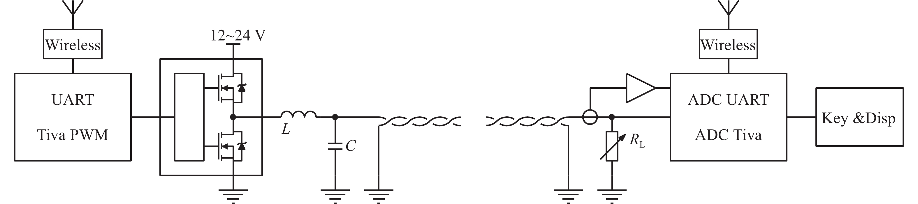
    • 实验模型模拟电能产生、输电和监控过程,并在用户端监控电压和电流,反馈至电能产生部分实时调节输出。元件包含降压式变换电路(BUCK电路)、直流电压检测模块、直流电流检测模块三个模块,微控制器包括负载监控显示、脉冲宽度调制输出(PWM波形输出)、数值检测、蓝牙传输、PID控制五个方面,微电网电路图如图1所示。

      Figure 1.  Circuit diagram of DC microgrid

    • 微电网维持恒压或者恒流的主要手段是BUCK电路。它是一种最为常用的直流降压变换器,在各类电源中应用广泛。图2为BUCK电路原理图,在连续工作的时候,电感充电和放电的电流变化量必须和为零,通过这一特点可以实现降压输出。

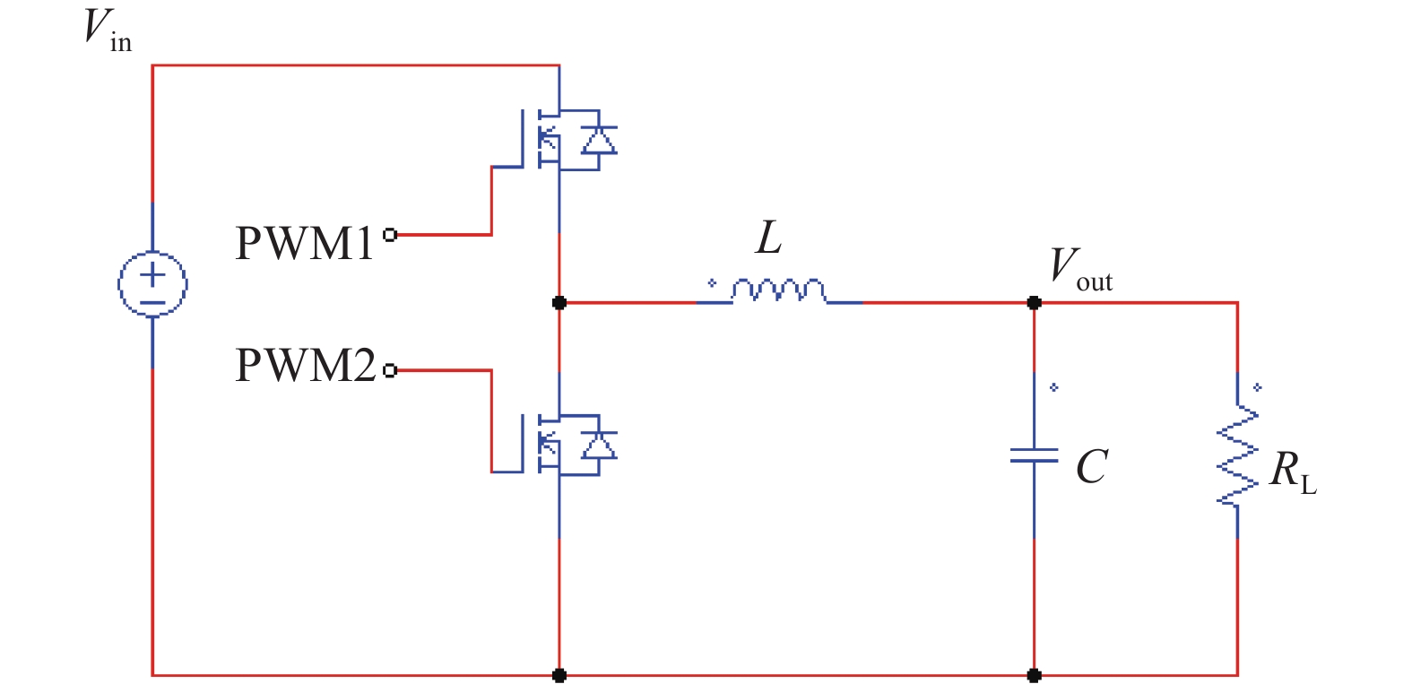
      Figure 2.  Schematic diagram of BUCK circuit

      PWM1和PWM2是一对互补的带死区的PWM波,当PWM1为高电平时电感充电:

      $$ \Delta {{I}_{{\rm{L}} + }} = \left( {{{V}_{{\rm{IN}}}} - {{V}_{{\rm{OUT}}}}} \right){{T}_{{\rm{ON}}/{\rm{L}}}} $$ (1)

      当PWM2为高电平时,电感放电:

      $$ \Delta {{I}_{{\rm{L}} - }} = \left( {0 - {{V}_{{\rm{OUT}}}}} \right){{T}_{{\rm{OFF}}/{\rm{L}}}} $$ (2)

      电流变化量为0:

      $$ \Delta {I}_{{\rm{L}}-}+\Delta {I}_{\mathrm{L}+}= 0 $$ (3)

      以上可以得出:

      $$ \frac{{V}_{\mathrm{O}\mathrm{U}\mathrm{T}}}{{V}_{\mathrm{I}\mathrm{N}}}=\frac{{T}_{\mathrm{O}\mathrm{N}}}{{{T}_{\mathrm{O}\mathrm{N}}+T}_{\mathrm{O}\mathrm{F}\mathrm{F}}} $$ (4)

      根据这个公式可知当输入${T}_{\mathrm{O}\mathrm{N}}$${T}_{\mathrm{O}\mathrm{F}\mathrm{F}}$发生改变时可以改变输出的电压大小,通过改变PWM波的占空比来改变${T}_{\mathrm{O}\mathrm{N}}$${T}_{\mathrm{O}\mathrm{F}\mathrm{F}}$,进一步改变输出电压的大小。

      由于输电线往往需要远距离传输,所以本次模拟运用蓝牙无线传输技术实现远距离数据传输。

      为实现电路中自动闭环控制,运用Simulink中PID tuner进行结构建模分析,得到理想闭环控制参数。

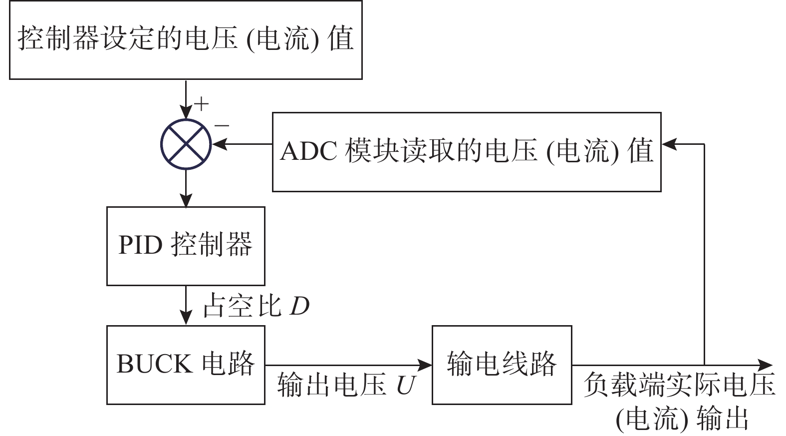
    • 本系统本质是通过负载端检测的电压电流值输入到主控端,然后在主控端对电压电流值进行操作之后,换算成为PWM波的占空比输出, BUCK电路会根据输出占空比的大小来改变输出电压的大小,通过如上的操作实现恒流或者恒压的变化,根据上述的系统的实际原理,完成系统的仿真模型,如图3所示。

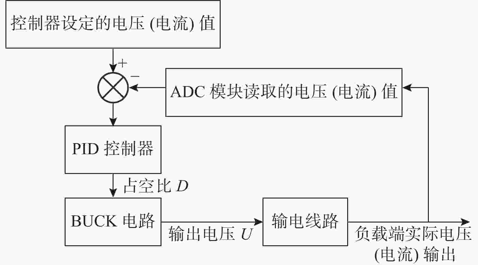
      Figure 3.  System block diagram

    • 受限于蓝牙采样有0.1 s的时间间隔,所以整体调节时间比较长,采用Simulink的参数自动生成得出在不同要求下的参数。

      在恒流时候的参数为:P=200,I=100,D=20;

      恒压的时候的参数为: p=1,I=33,D=0.1。
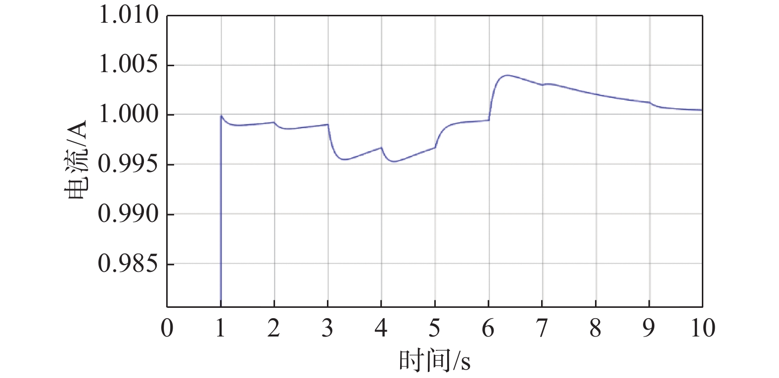
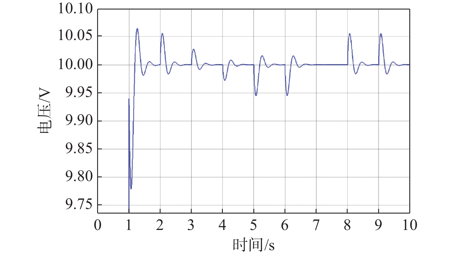
    • 通过PID参数设置之后输入阶跃响应对应的结果如图4图5所示,可以看到响应时间在10 s左右,在10 s后仍会有轻微的振荡,可以暂时使用这一组参数,在实验中可以进一步对参数进行优化,以获得满足要求的系统性能。

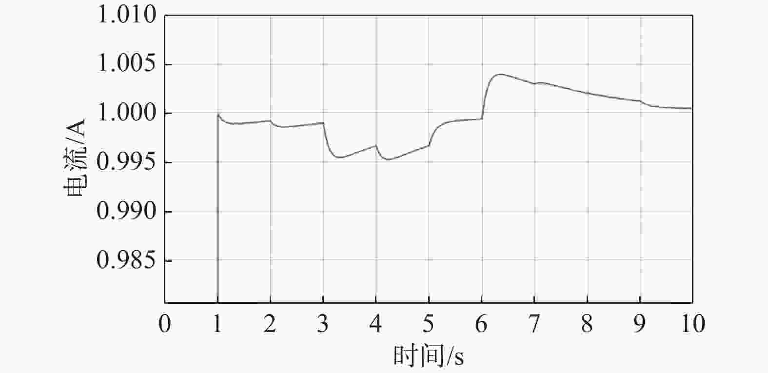
      Figure 4.  Current simulation waveform

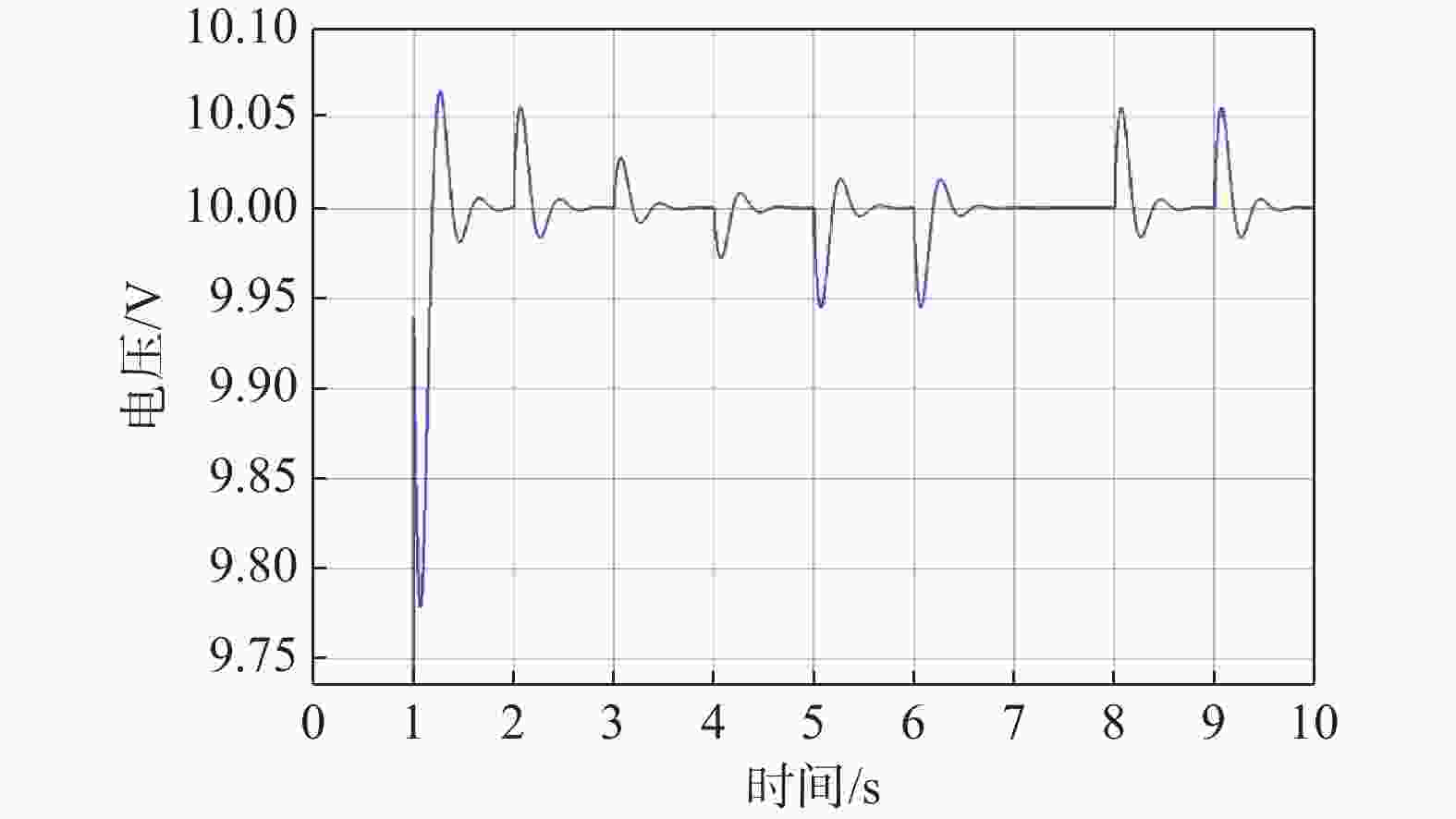
      Figure 5.  Voltage simulation waveform

    • 焊接元件BUCK电压转换器、直流电流检测模块,再将这些模块和微控制器和实验用电源,实验用负载等连接,其中实验用电源是可以输出12~24 V直流电压,实验用负载实际上是一个最大为100 Ω的电阻器,具体连接图如图6所示。

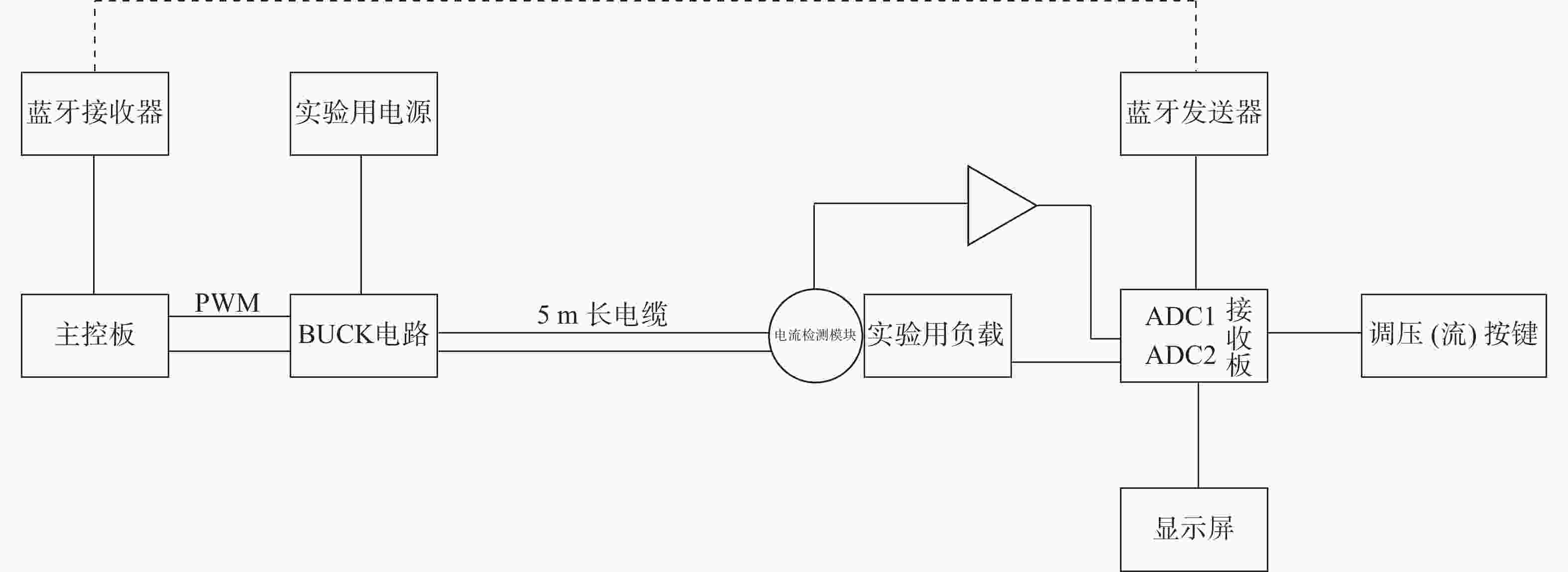
      Figure 6.  Hardware connection diagram

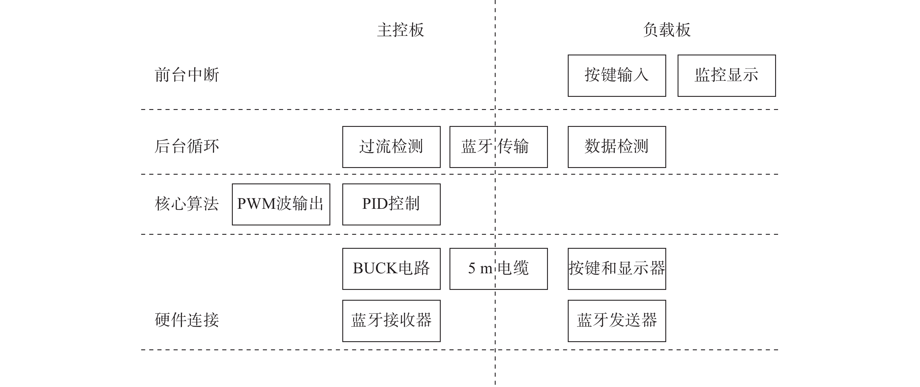
    • 本次实验软件主要由前台中断、后台循环、核心算法、硬件连接等4个主要方面组成,实际涵盖了监控显示、PWM波输出、数值检测、蓝牙传输、PID控制等等,软件架构图如图7所示。

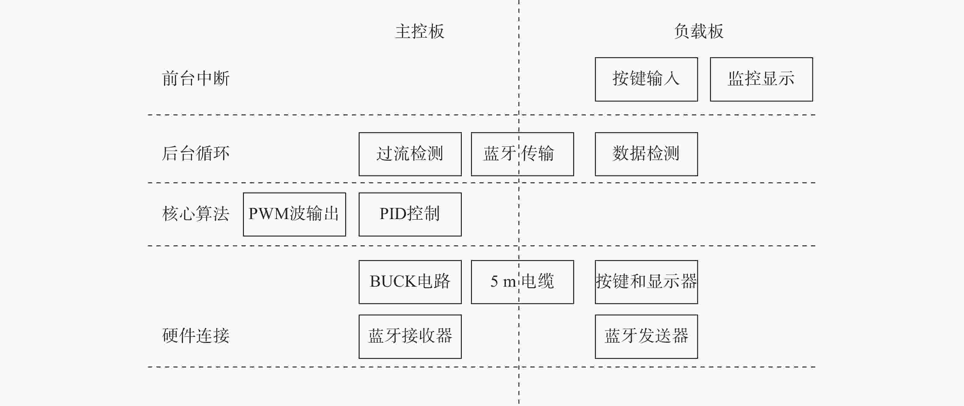
      Figure 7.  Software architecture diagram

    • 负载监控检测和显示设定电压、实测电压和实测电流,按键调节输出电压,调节挡位和换页查看,同时为了实验安全,设置了安全电流为2 A,当负载过小时检测过流显示error,5 s后重新上电。

    • TIVA-C模数转换器ADC模块实现监测部分数值检测,手动改变检测端负载,进行电压电流端输出拟合,拟合结果为一线性方程,将这个方程手动输入到微控制器中,在实验中,每0.1 s读取一次电压和电流的大小。

    • 实验中使用HC-05蓝牙芯片,首先将两个蓝牙通信模块进行匹配之后再在系统中使用,每0.1 s 将负载端的检测数据(包括数值检测出的电压电流和设定的电压或电流)传输至主控板,主控板再做出相应的调整措施。

    • 当检测出电流超过2 A时启动过流保护,此时微控制器输出占空比为0,相当于切断电源,保护电路元件不被高电流烧毁,5 s后重新上电,若电流小于2 A则电路重新正常工作,如果电流仍然超过2 A电路继续断电直到电流小于2 A。

    • 经多次实验,得出能够驱动BUCK电路的频率应大于10 kHz,小于100 KHz,输出一对带死区且占空比可调的PWM波,这样理论输出电压是输入电压大小乘以占空比,实验中由于有电缆的分压所以占空比比理论值高。

    • 电压实际值为4.64 V,电流实际值为0.225 A,这时检测出来的电压为4.60 V,电流为0.23 A,电压和电流检测大小和实际值相差在实验误差允许范围(2%)之内,符合日常使用的标准。

    • 保持设定电压为5 V,短路运行,这是电路瞬间断电, 5 s后重新上电。保持设定值不变,断路运行,实际电压输出为4.93 V,误差值为1.4%,接上负载后,改变负载(在实验中使用滑动变阻器代替)大小,记录实际电压和电流值,并算出误差值,然后保持负载大小不变,改变设定电压大小记录数据,最终数据如表1所示。

      设定电压/V实际电压/V实际电流/A误差值/%
      54.930.001.40
      54.971.170.60
      54.960.810.60
      32.980.510.67
      87.941.340.75

      Table 1.  Constant voltage test experimental data

      表1可知恒压测试最终有负载时输出电压误差基本小于1%,断路运行时电压输出误差小于2%。

    • 保持设定电流为1A,直接短路运行,实际电流输出为0.986A,误差值为1.4%,接上负载之后,改变负载大小,记录实际电流和电压值,并算出误差值,然后保持输出电压不变,改变设定电流大小记录数据,最终数据如表2所示。

      设定电流/A实际电流/A实际电压/V误差值/%
      1.00.9860.001.40
      1.00.9917.910.90
      1.00.9925.930.80
      0.50.4965.930.80
      1.21.1915.940.75

      Table 2.  Constant current test experimental data

      表2可知恒流测试最终有负载时输出电流误差基本小于1%,短路运行时电流输出误差小于2%。

    • 通过硬件实验,实现使用微控制器控制微电网进行恒压或者恒流输出,同时做到在负载大小变化的情况下保持恒压或者恒流,可以以相对平稳的速度重新恢复平衡,让微电网工作在一个新的功率下;在更改设定的电压或者电流时,也可以以相对平稳的速度改变微电网的输出功率,这对微电网的稳定运行有着重要意义,采用Simulink对PID参数进行设计和提前模拟仿真,让PID参数设置合理,可减少在硬件实验过程中出现实验隐患。

Reference (10)

Catalog

    /

    DownLoad:  Full-Size Img  PowerPoint
    Return
    Return