• Peer Review
  • Non-profit
  • Global Open Access
  • Green Channel for Rising Stars
Volume 10 Issue 1
Jan.  2023
Turn off MathJax
Article Contents

LIU Huaquan, LI Yuansong, PAN Shengping, ZHANG Xin, ZHAO Yong. Key Technology of Construction Process Control of Guide Frame Platform Suction Bucket Foundation[J]. SOUTHERN ENERGY CONSTRUCTION, 2023, 10(1): 98-104. doi: 10.16516/j.gedi.issn2095-8676.2023.01.012
Citation: LIU Huaquan, LI Yuansong, PAN Shengping, ZHANG Xin, ZHAO Yong. Key Technology of Construction Process Control of Guide Frame Platform Suction Bucket Foundation[J]. SOUTHERN ENERGY CONSTRUCTION, 2023, 10(1): 98-104. doi: 10.16516/j.gedi.issn2095-8676.2023.01.012

Key Technology of Construction Process Control of Guide Frame Platform Suction Bucket Foundation

doi: 10.16516/j.gedi.issn2095-8676.2023.01.012
  • Received Date: 2022-04-28
  • Rev Recd Date: 2022-07-20
  • Available Online: 2022-12-10
  • Publish Date: 2023-01-11
  •   Introduction  The present, design and construction technology of suction bucket foundation is not mature, and there is lack of the normative guidance documents, the special research on the key technology of the construction process control of the suction bucket was implemented.   Method  Taking an offshore wind farm project as the background, based on the measured data of orientation platform foundations, statistical analysis, data mining, process back in the inversion method and technology was used.   Result  The constitution and function of the complete set of installation equipment of suction bucket foundation and the intelligent and digital control system are described in detail. The control parameters and control standards in the construction process of suction bucket foundation of guide frame platform are discussed. The feasibility analysis and calculation method and parameter value method of suction bucket penetration/jacking are summarized. The key points and control methods of each link in the whole process of suction bucket from penetration to jacking and recovery are put forward.   Conclusion  Finally, according to the measured construction data of seven four-pile guide frame platform suction bucket foundation, the variation characteristics of control parameters and the control effect during the construction of suction bucket foundation are illustrated. It can be used for reference in the design and construction of similar suction bucket platform foundation.
  • [1] 张浦阳, 黄宣旭. 海上风电吸力式筒型基础应用研究 [J]. 南方能源建设, 2018, 5(4): 1-11. DOI:  10.16516/j.gedi.issn2095-8676.2018.04.001.

    ZHANG P Y, HUANG X X. Application research on suction bucket foundation for offshore wind power [J]. Southern Energy Construction, 2018, 5(4): 1-11. DOI:  10.16516/j.gedi.issn2095-8676.2018.04.001.
    [2] 毋晓妮, 廖倩, 李晔. 海上风机吸力式桶形基础承载特性研究综述 [J]. 海洋技术学报, 2020, 39(1): 91-106. DOI:  10.3969/j.issn.1003-2029.2020.01.014.

    WU X N, LIAO Q, LI Y. A review on the bearing capacity studies of the suction bucket foundation for offshore wind turbines [J]. Journal of Ocean Technology, 2020, 39(1): 91-106. DOI:  10.3969/j.issn.1003-2029.2020.01.014.
    [3] 范荣山, 张健. 深水导管架在海上风电项目的施工方法探讨 [J]. 水电与新能源, 2020, 34(9): 32-35. DOI:  10.13622/j.cnki.cn42-1800/tv.1671-3354.2020.09.009.

    FAN R S, ZHANG J. The construction of deepwater jacket foundation in far-reaching offshore wind power projects [J]. Hydropower and New Energy, 2020, 34(9): 32-35. DOI:  10.13622/j.cnki.cn42-1800/tv.1671-3354.2020.09.009.
    [4] ANDERSEN K H, JOSTAD H P. Shear strength along inside of suction anchor skirt wall in clay [C]//Anon. Proceedings of the Offshore Technology Conference, Houston, May 3-6, 2004. Houston: OTC, 2004. DOI:  10.4043/16844-MS.
    [5] HOULSBY G T, BYRNE B W. Design procedures for installation of suction caissons in clay and other materials [J]. Proceedings of the Institution of Civil Engineers-Geotechnical Engineering, 2005, 158(2): 75-82. DOI:  10.1680/geng.2005.158.2.75.
    [6] American Petroleum Institute. Design and analysis of stationkeeping systems for floating structures: API RP 2SK [S]. New York: API Publishing, 2015.
    [7] American Petroleum Institute. Geotechnical and foundation design considerations: API RP 2GEO [S]. New York: API Publishing, 2011.
    [8] DNVGL-RP-C212. Offshore soil mechanics and geotechnical engineering [EB/OL]. (2019-07-01)[2022-04-28]. https://www.document-center.com/standards/show/DNVGL-RP-C212/history/2017/A1%20EDITION.
    [9] HOULSBY G T, BYRNE B W. Design procedures for installation of suction caissons in sand [J]. Geotechnical Engineering, 2005, 158(3): 135-144. DOI:  10.1680/geng.2005.158.3.135.
    [10] SENDERS M, RANDOLPH M F. CPT-based method for the installation of suction caissons in sand [J]. Journal of Geotechnical and Geoenvironmental Engineering, 2009, 135(1): 14-25. DOI:  10.1061/(ASCE)1090-0241(2009)135:1(14).
    [11] 丁红岩, 贾楠, 张浦阳. 砂土中筒型基础沉放过程渗流特性和沉贯阻力研究 [J]. 岩土力学, 2018, 39(9): 3130-3138+3146. DOI:  10.16285/j.rsm.2016.2913.

    DING H Y, JIA N, ZHANG P Y. Research of seepage characteristics and penetration resistance during installation of bucket foundations in sand [J]. Rock and Soil Mechanics, 2018, 39(9): 3130-3138+3146. DOI:  10.16285/j.rsm.2016.2913.
    [12] 朱儒弟, 辛海英, 高恒庆, 等. 桶形基础平台负压沉贯遥测遥控技术方案设计 [J]. 海岸工程, 1999, 18(1): 85-89.

    ZHU R D, XIN H Y, GAO H Q, et al. Technological scheme design for remote detection and telecontrol of suction penetration of bucekt foundation of flatforms [J]. Coastal Engineering, 1999, 18(1): 85-89.
    [13] 丁忠军, 张士华, 徐松森, 等. 桶基平台负压沉贯过程监测与控制技术研究 [J]. 海洋工程, 2010, 28(3): 102-106. DOI:  10.16483/j.issn.1005-9865.2010.03.009.

    DING Z J, ZHANG S H, XU S S, et al. Research of monitoring and controlling technology during the bucket foundation platform suction penetration [J]. The Ocean Engineering, 2010, 28(3): 102-106. DOI:  10.16483/j.issn.1005-9865.2010.03.009.
    [14] 李大勇, 吴宇旗, 张雨坤, 等. 砂土中桶形基础吸力值的设定范围 [J]. 岩土力学, 2017, 38(4): 985-992+1002. DOI:  10.16285/j.rsm.2017.04.009.

    LI D Y, WU Y Q, ZHANG Y K, et al. Determination of suction range for penetration of suction caissons in sand [J]. Rock and Soil Mechanics, 2017, 38(4): 985-992+1002. DOI:  10.16285/j.rsm.2017.04.009.
  • 通讯作者: 陈斌, bchen63@163.com
    • 1. 

      沈阳化工大学材料科学与工程学院 沈阳 110142

    1. 本站搜索
    2. 百度学术搜索
    3. 万方数据库搜索
    4. CNKI搜索

Figures(6)  / Tables(2)

Article Metrics

Article views(207) PDF downloads(48) Cited by()

Related

Key Technology of Construction Process Control of Guide Frame Platform Suction Bucket Foundation

doi: 10.16516/j.gedi.issn2095-8676.2023.01.012

Abstract:   Introduction  The present, design and construction technology of suction bucket foundation is not mature, and there is lack of the normative guidance documents, the special research on the key technology of the construction process control of the suction bucket was implemented.   Method  Taking an offshore wind farm project as the background, based on the measured data of orientation platform foundations, statistical analysis, data mining, process back in the inversion method and technology was used.   Result  The constitution and function of the complete set of installation equipment of suction bucket foundation and the intelligent and digital control system are described in detail. The control parameters and control standards in the construction process of suction bucket foundation of guide frame platform are discussed. The feasibility analysis and calculation method and parameter value method of suction bucket penetration/jacking are summarized. The key points and control methods of each link in the whole process of suction bucket from penetration to jacking and recovery are put forward.   Conclusion  Finally, according to the measured construction data of seven four-pile guide frame platform suction bucket foundation, the variation characteristics of control parameters and the control effect during the construction of suction bucket foundation are illustrated. It can be used for reference in the design and construction of similar suction bucket platform foundation.

LIU Huaquan, LI Yuansong, PAN Shengping, ZHANG Xin, ZHAO Yong. Key Technology of Construction Process Control of Guide Frame Platform Suction Bucket Foundation[J]. SOUTHERN ENERGY CONSTRUCTION, 2023, 10(1): 98-104. doi: 10.16516/j.gedi.issn2095-8676.2023.01.012
Citation: LIU Huaquan, LI Yuansong, PAN Shengping, ZHANG Xin, ZHAO Yong. Key Technology of Construction Process Control of Guide Frame Platform Suction Bucket Foundation[J]. SOUTHERN ENERGY CONSTRUCTION, 2023, 10(1): 98-104. doi: 10.16516/j.gedi.issn2095-8676.2023.01.012
  • 吸力桶基础因其施工时间短、工效高、可重复利用等诸多优点,具有广阔的应用前景[1]。然而,相对于传统的打入桩施工,其工艺更为复杂,涉及技术含量高,如何能保证吸力桶顺利沉贯到设计深度,达到设计承载力及功能要求,是业界关注的热点问题[2-3]。纵观国内外吸力桶的发展历程与技术现状[3-5],吸力桶施工控制关键技术归纳为三个方面:(1)贯入阻力与控制指标的计算;(2)控制参数的实时监测与上传;(3)成套的安装设备与控制技术。

    关于黏性土中沉贯阻力的计算相对较为成熟,API[6-7]和DNV GL-C212[8]中均推荐了具体计算方法。Houlsby[9]、Senders[10]等研究砂土中渗透破坏机理,提出临界吸力计算公式,并应用于桶型基础沉贯施工和设计;丁红岩[11]等开展吸力桶在不同土质中的模型试验,提出沉贯过程中应控制吸力以避免渗透破坏或土塞隆起。在浪、流环境下对吸力桶沉贯进行监测与控制也是目前尚未很好解决的难题。朱儒弟[12]、丁忠军[13]等分别在遥测遥控系统领域进行了大量技术开发。工程技术人员经过多年的潜心研究,积累了丰富经验,研制一套技术先进,功能相对完善的施工安装设备与控制系统,在广东某海上风电场施工取得圆满成功,各项指标均达到预想效果。

    本文以广东沿海某海上风电场导向架平台基础施工项目为背景,详细探讨吸力桶施工过程控制中的相关技术问题,以供对类似吸力桶基础设计与施工时参考。

  • 贯入可行性分析是将待施工机位地层沿深度按一定厚度分层,验算各项控制指标是否能达到顺利贯穿的技术要求。其核心内容是精确计算每层贯入阻力、临界吸力、允许吸力和所需吸力。

  • 目前国内外工程设计主要引用API和DNV推荐方法:静力法和Based-CPTU法两种,本次研究采用经修正后的静力法计算公式。

    假定吸力桶内外侧壁摩擦系数相同,并不考虑土塞效应,给定贯入深度Hn的贯入阻力计算统一表达式:

    $$ \begin{split} &{Q_{{\text{tot}}}} = {Q_{{\text{side}}}} + {Q_{{\text{tip}}}} = \sum\limits_{{i = 1}}^{n} {{\text{π}} {D_{\text{0}}}\Delta {h_{i}}} \cdot ({\alpha _{i}}{S_{{\text{u}i}}} + {K_{i}}\gamma '{h_{i}}\tan {\delta _{i}}){\text{ + }}\\&({N_{{\text{c}n}}}{S_{{\text{untip}}}} + {N_{{\text{q}n}}}\gamma '{\text{ }}{h_{n}}) \cdot {A_{{\text{tip}}}} \end{split} $$ (1)

    式中:

    Qtot —— 总贯入阻力(kN);

    Qside——桶侧壁摩阻力(kN);

    Qtip ——桶端部阻力(kN);

    n ——分层计算的总层数;

    Sui ——第i分层土体不排水抗剪强度(kPa);

    K ——侧压力系数,一般采用实测值。若无实测数据,对于黏土,K=0;对于无黏性土,K=0.8,或按K=(1-sinφ)计算;

    φ ——土层内摩擦角(°);

    δ ——桶与土体之间的摩擦角(°)。当没有实测值时,δ可按文献[6]表1取值。

    名称规格参数数量备注
    泵撬块系统(1)电压:380 V;
    (2)功率:≥120 kW;
    (3)频率:50 Hz;
    (4)水泵:2×200 m3/h。
    1套水泵采用一用一备,
    最大流量400 m3/h。
    中控室(1)长×宽×高:
    6 m×2.4 m×2.6 m;
    (2)电压:220 V;功率:
    5 kW;频率:50 Hz。
    1个动力控制、操
    作控制兼用。
    胶带缆150 m1套电缆、液压管
    线、信号缆铠装。

    Table 1.  Specification parameters of suction bucket penetration/jacking equipment system

    Ncn ——承载力系数,其取值与计算目的有关[6]

    Nqn ——承载力系数,对于黏土,一般取1.0;对于砂土参见API[6]

    Suitip——桶端部不排水抗剪强度均值(kPa);

    Atip ——桶端圆环面积(m2);

    αi ——安装过程中土体的黏性系数,通常定义为重塑土与原状土剪切强度的比值,为土体敏感性的倒数,当没实测数据时,可按式(2)计算确定:

    $$ \alpha=\left\{\begin{array}{cc} 1 & \psi \leqslant 0.25 \\ 0.5 \psi^{-0.5}, & 0.25 < \psi \leqslant 1.0 \\ 0.5 \psi^{-0.25}, & \psi > 1.0 \end{array}\right. $$ (2)

    式中:

    $ \psi = {s_{\rm{u}}}/p{'_0} $$p{'_0} $——计算点的有效竖向应力。

  • 1)黏性土。将引起桶端整体反向失效以及大量土体吸入桶内的吸力定义为给定深度处的极限吸力ΔUcirt,其值按式(3)计算:

    $$ \Delta {U_{{\rm{crit}}}}{\rm{ = }}{N_{\rm{c}}} \cdot S_{{\rm{utip}}}^{{\rm{AVE}}} + \frac{{{A_{{\rm{inside}}}} \cdot {{({\alpha _{{\rm{ins}}}} \cdot {S_{{\rm{uDSS}}}})}_{{\rm{AVE}}}}}}{{{A_{{\rm{in}}}}}} $$ (3)

    式中:

    Ainside——桶壁的内侧面积(m2);

    Ain ——桶内圆截面积(m2),其余符号同前。

    2)无黏性土。对于均匀无黏性土层,Sender和Randolph[10]等人给出经验公式:

    $$ \Delta {U_{{\text{crit}}}} = \left\{ {{\text{π}} - \arctan [5{{(H/D)}^{0.85}}} \right\}\left( {2 - \frac{2}{{\text{π}} }} \right){\text{ }}H\gamma ' $$ (4)

    式中:

    D —— 吸力桶直径(m);

    H —— 吸力桶高度(m)。

    3)对于层状土层夹无黏性土层。本文建议先按式(3)计算无黏性土层的直接上覆黏土层的临界吸力,再按分层厚度代入式(4)计算无黏性土层的临界吸力,两者相加即为计算混合土层的临界吸力。

  • 考虑桶内土体渗透破坏与气穴效应后,施加于桶的许用吸力ΔUallow按式(5)确定:

    $$ \Delta {U}_{\text{allow}}=\mathrm{min}\left( {\dfrac{\Delta {U}_{\text{crit}}}{k}\text{,}{\gamma }_{\text{w}}h} \right) $$ (5)

    式中:

    k ——安全系数,推荐值为1.5;

    γw——海水容重(kN/m3);

    h ——吸力桶顶水深(m)。

  • 吸力桶所需吸力ΔUreq按式(6)确定:

    $$ \Delta {U_{{\text{req}}}} = \dfrac{{{Q_{{\text{tot}}}} - W'}}{{{A_{{\text{in}}}}}} $$ (6)

    式中:

    W′——吸力桶浮重及上部平台分配的重量(kN);

    Ain——吸力桶的有效净截面积(m2)。

  • 自重贯入深度LSWP是抽水系统启动前的控制点,此时,系统需静置一段时间,使桶体内部形成一定的封闭空间。入泥深度可由式(7)和式(8)通过试算得到:

    $$ \displaystyle \sum\limits_{i = 1}^n {2{\text{π}}\Delta {h_{i}}} {D_{\text{0}}}{\alpha _{i}}{s_{{\text{u}i}}} + ({N_{n{\text{c}}}} \cdot {S_{{\text{nutip}}}} + {N_{n{\text{q}}}}\sigma {'_{n}}) \cdot {A_{{\text{tip}}}} - W' = 0 $$ (7)

    式中:

    Δhi ——第i分层的层高(m);

    Sui ——第i分层土的不排水抗剪强度(kPa);

    αui ——第i分层土的计算系数;

    D0 ——吸力桶体的平均直径(m);

    NcnNqn ——第n分层土的计算系数;

    W′ ——桩及其上部结构的总有效重量(kN)。

    $$ {L_{{\text{SWP}}}} = \displaystyle \sum\limits_{i = 1}^n {\Delta {h_{i}}} $$ (8)
  • 吸力桶安装设备控制系统主要由:泵撬块系统、控制系统和胶带缆收放系统等三个子系统组成。

    1)泵撬块系统

    泵撬块系统主要由四部分组成:

    电子舱:电子舱装有吸力桶状态信息监测传感器,可以实时监测桶体内外压力差、平台架底座的水平度,并通过电缆传输到水上主控系统;液压机构:逻辑阀门控制系统;电动水泵:负压桶吸力贯入与顶升;锁紧机构:泵撬块泵口与负压桶管汇法兰基座的锁紧、解脱,如图1所示。

    Figure 1.  Connection between the pump skid and the platform frame

    2)控制系统

    控制系统可实时监测结构水平度、负压桶内外压差、贯入深度等。根据监测数据,通过计算机系统调整泵撬块控制系统,实现安装各项设计指标控制在设定范围内。

    3)胶带缆收放系统

    胶带缆收放系统由胶带绞车、电缆组成。主要用于连接水下泵撬块系统与水上主控制系统的通讯电缆。因防水、防腐蚀、防摩擦、防碰撞等要求,需进行铠装。

    吸力桶贯入/顶升装备系统规格参数见表1

  • 考虑到导向架基础临时性特点,施工控制按如下标准执行:

    1)土塞隆起量小于200 mm。

    2)吸力桶贯入施工过程中,实际吸力在任何情况下不能超过屈曲控制线。

    3)贯入过程中应实时监测吸力桶的内外压差、贯入度、倾斜度、桶体状况。

    4)多桶导向架风机基础贯入下沉应以标高控制,基础须贯入至设计高程。

    5)多桶导向架风机基础贯入下沉,应控制下沉速率:

    (1)自重下沉:0~2 m,贯入速率v$ \leqslant $3 cm/min;2 m至自重下沉阶段完成,v$\leqslant $5 cm/min。

    (2)负压下沉:v$\leqslant $2.5 cm/min。

    6)桩位允许偏差:

    绝对位置允许偏差<500 mm;高程允许偏差(−500 mm,100 mm);水平度偏差≤2‰。

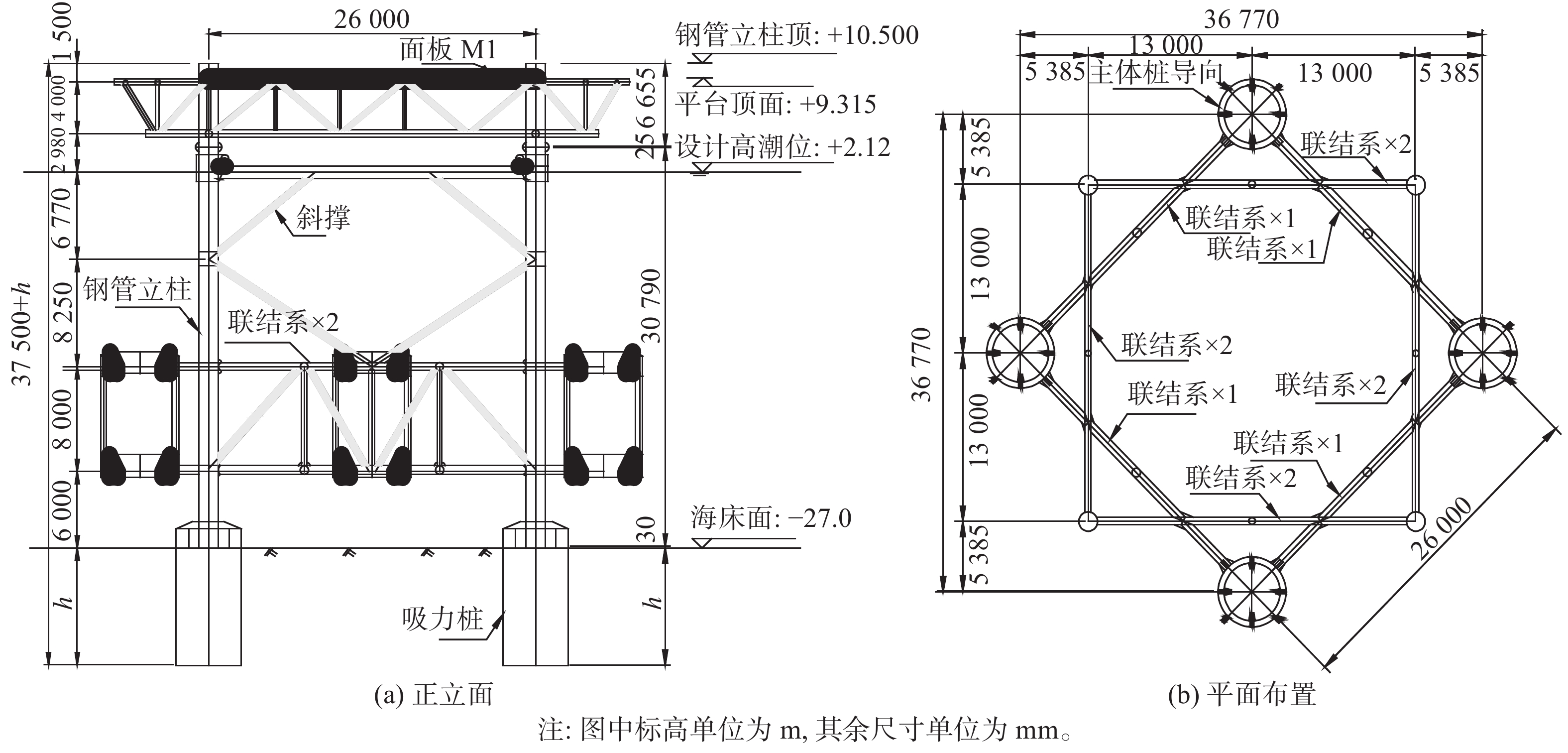
  • 某海上风电机组施工四桩导向架平台吸力桶基础(WT42),平台架尺寸、永久桩位与吸力桶平面布置平面如图2所示。贯入时桶顶荷载776 kN,吸力桶浮重410 kN。桶直径5 m,壁厚30 mm,设计贯入深度6.5 m。桩位水深29 m,地层及计算参数如表2所示。

    Figure 2.  Four-pile platform frame arrangement

    土层层底深度
    h/m
    浮重度
    γ′/(kN·m−3)
    不排水抗剪强度
    Cu/kPa
    内摩擦角
    φ/(°)
    ①-1淤泥质黏土2.17.28.0
    ①-2黏土4.27.630.0
    ①-3砾砂7.07.249.0
    ②-1细到粗砂10.19.335.0
    ②-2黏土11.48.662.0
    ②-4粉砂13.89.6100.0
    ②-5黏土14.411.730.0
    ②-6细到粗砂17.67.788.0

    Table 2.  The stratum and calculation parameters of WT42 platform

  • 1)桶内外压力差监测。通过抽水泵口压力传感器与吸力桶内顶端压力传感器的读数,可观测到每个桶内外压力差。压力传感器通过安装在导向平台底部管汇系统接入泵撬块系统,再通过脐带缆与船上主控制系统联接。

    2)垂直度监测。泵撬块系统中,安装有高精度双轴倾角传感器与方位电罗经,通过倾角读数与方位可换算出平台架系统的空间姿态。同时,配合导向架平台顶3个GPS(利用RTK技术)测点的3D坐标变化,进行比对校验。

    3)贯入深度监测。贯入深度监测有两种方式,一种是直接用平台架顶GPS测点坐标换算得到,目前这种方式没有纳入吸力桶主控系统;另一种是通过压力传感器间接测量。其监测原理如图3所示。

    Figure 3.  Principle of penetration parameter monitoring

    4)土塞高度监测。由于贯入过程中吸力桶处封闭状态,难以用传统的方法直接观测桶内泥面高度。本次研究提出利用压力传感器间接测量的方法。

    桶内负压值Δp,为吸力桶顶内外压力差,分别由1#传感器和2#传感器测量:

    $$ \Delta p = {p_1} - {p_2} $$ (9)

    沉贯深度HAS,为桶底与泥面高差,可通过0#传感器和1#传感器测量:

    $$ {H_{{\text{AS}}}} = {H_{\text{b}}} - ({H_{\text{w}}} - {H_{\text{s}}}) = {H_{\text{b}}} - \frac{{{p_{\text{0}}} - {p_{\text{1}}}}}{{{\gamma _{\text{w}}}}} $$ (10)

    式中:

    Hb——桶高(m);

    γw ——海水重度(m)。

    土塞高度HAT,可由2#传感器和3#传感器所测压力通过计算确定:

    $$ {H_{{\text{AT}}}} = \frac{{{p_3} - {p_2}}}{{{\gamma _{\text{w}}}}} $$ (11)

    5)其它还有电子舱温度、电机频率。均通过安装在泵撬块系统中电子舱内的传感器,与主控制台联系,实时监控电子舱内的环境与吸力桶的工作状态。

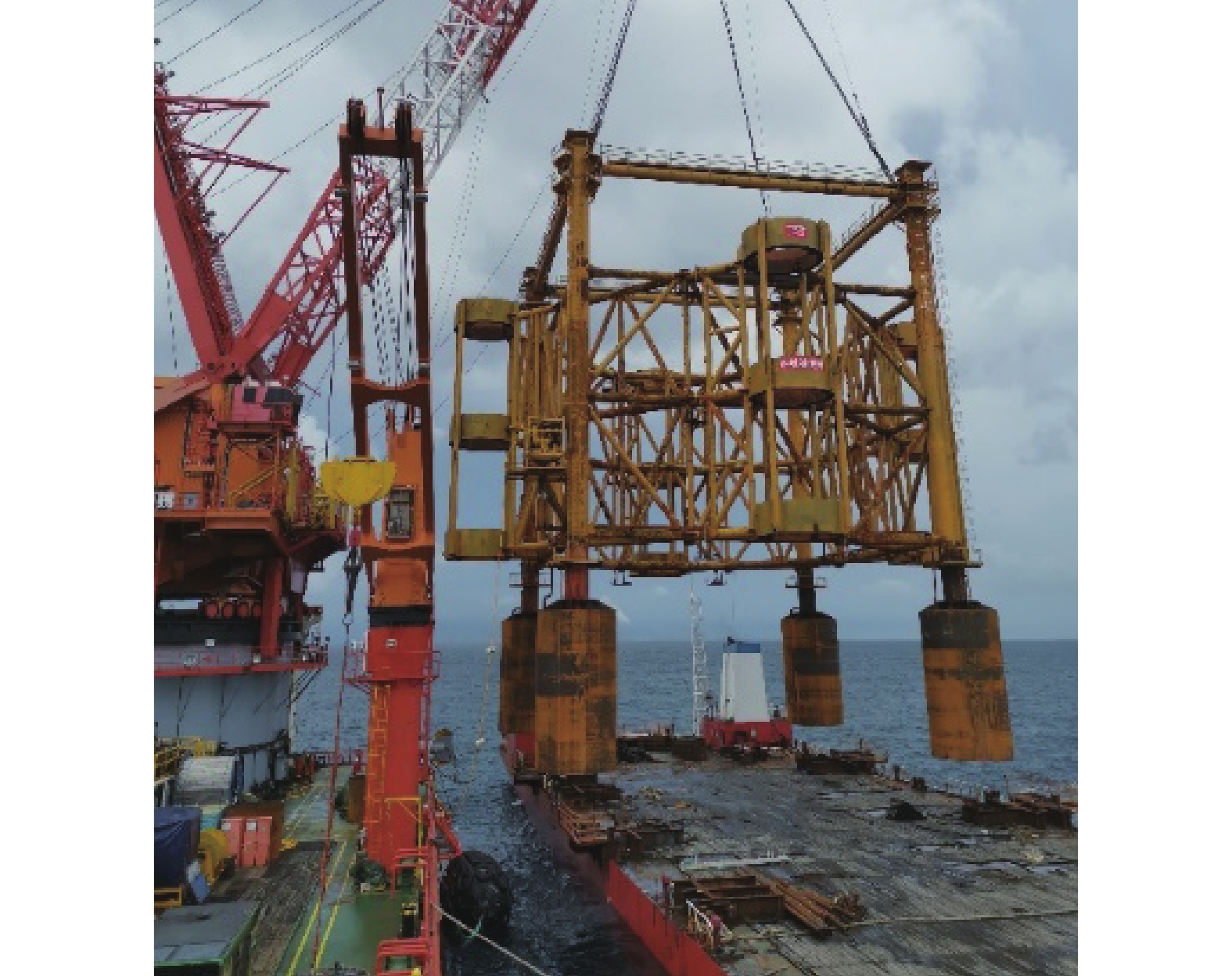
  • 1)导向架吊装入水。将吸力桶导向架起吊,移至拟安装位置,吊装设备松钩、将导向架放入水中,在吸力桶底端刚接触到泥面时,暂停松钩。在此过程中,吸力泵排水口打开,使得桶内的水可自由排出。通过操作吊装设备的扒杆动作、卷扬机辅助调整牵引绳或移船等操作,使吸力桶进行小范围移动调整;同时通过水下电罗经监测吸力桶导向架基础的方位角,通过短基线定位系统监测吸力桶导管架的坐标,直到方位角和坐标均满足设计要求时,停止移动导向架基础,如图4所示。

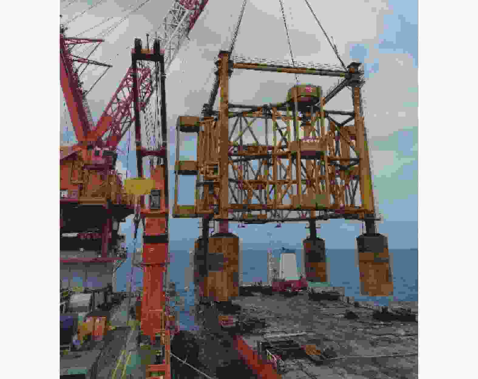
    Figure 4.  Four pile platform frame hoisting

    2)自重入泥。吊装设备继续缓缓松钩,吸力桶导向架靠自重使其吸力桶贯入海床土体。吸力桶下放至自重入泥时,监控入泥深度和结构平台水平度,调整在设计允许范围内。严格控制桶体下沉速度$ \leqslant $3 m/h。当吊机重量约为30 t时,视为自重入泥结束。保持约30 t吊重以保证结构在初始贯入时的水平度。静置20~30 min,保证形成初始密封条件。

    3)负压贯入。自重入泥结束后,启动泵撬块系统,开始吸力贯入作业。贯入过程中根据测控设备监控水平度、贯入深度、桶体内外压差等参数。同时也可通过水下姿态仪和水下ROV等设备进行确认,直到吸力桶导向架基础贯入深度达到设计要求。若沉贯过程中,实时监测发现倾斜度超过允许值时,通过控制各自吸力桶上吸力泵的流量来控制吸力桶的贯入速度来调节水平度,直至吸力桶导向架安装到位及完成水平调节。

    4)土塞高度控制。土塞是指吸力桶在沉贯入土过程中,吸力桶内的土体在内外压力差和渗流的作用下向上抬升,提前与吸力桶的顶板接触,阻碍了吸力桶基础继续下沉。通过智能化、数字化的吸力泵系统进行实时监测和调节,严格控制以使土体不致形成过大土塞和发生整体失稳破坏。对于黏性土层只要控制桶内外压差不超过临界吸力,沉贯速率小于5 cm/min,土塞高度很小或不明显;对于无黏性土,尤其是粉土,应控制吸力在计算允许吸力80%以内[14],同时应密切关注压力传感器2与3的压差变化,一旦出现土塞,应及时控制吸力,以降低沉贯速率。

    5)水平度调整。吸力桶平台因各桶入泥深度不同而出现整体倾斜,当倾斜角大于允许值时需及时调整。自重沉贯阶段,平台整体倾斜可依靠吊机扶正;负压沉贯阶段,通过改变各桶的内外压差,改变沉贯速度,进而调节入泥深度,达到整体调平的目的。

    6)吸力桶顶升。作业结束后,将导向架顶升回收。启动泵撬系统锁紧装置,将泵撬块与桶体连接。吊机挂钩导向架,并预带大于导向架自重50%的提升力。开启泵撬块系统将负压桶导向架平台缓慢顶升,顶升过程中吊机需要与顶升作业协同配合,随着导向架平台顶升高度增加,吊机缓慢增加提升力。当顶升力逐渐减小时,吊机提升力大于导向架自重1倍以上。吊机逐渐加大提升力,将导向架负压桶全部提升到脱离泥面,顶升作业结束。
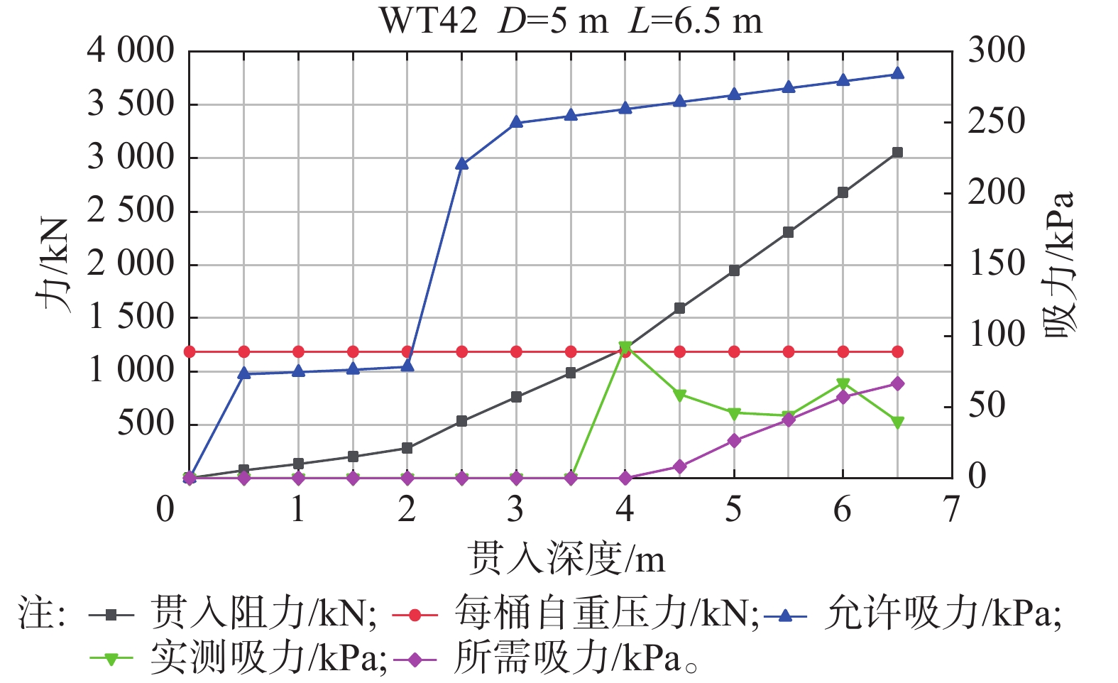
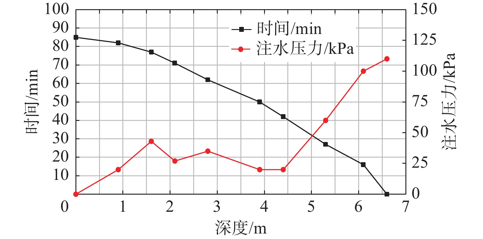
    典型吸力桶贯入下沉、顶升回收过程吸力与注水压力深度曲线分别见图5图6。平均贯入用时2.5 h,顶升回收用时1.5 h。

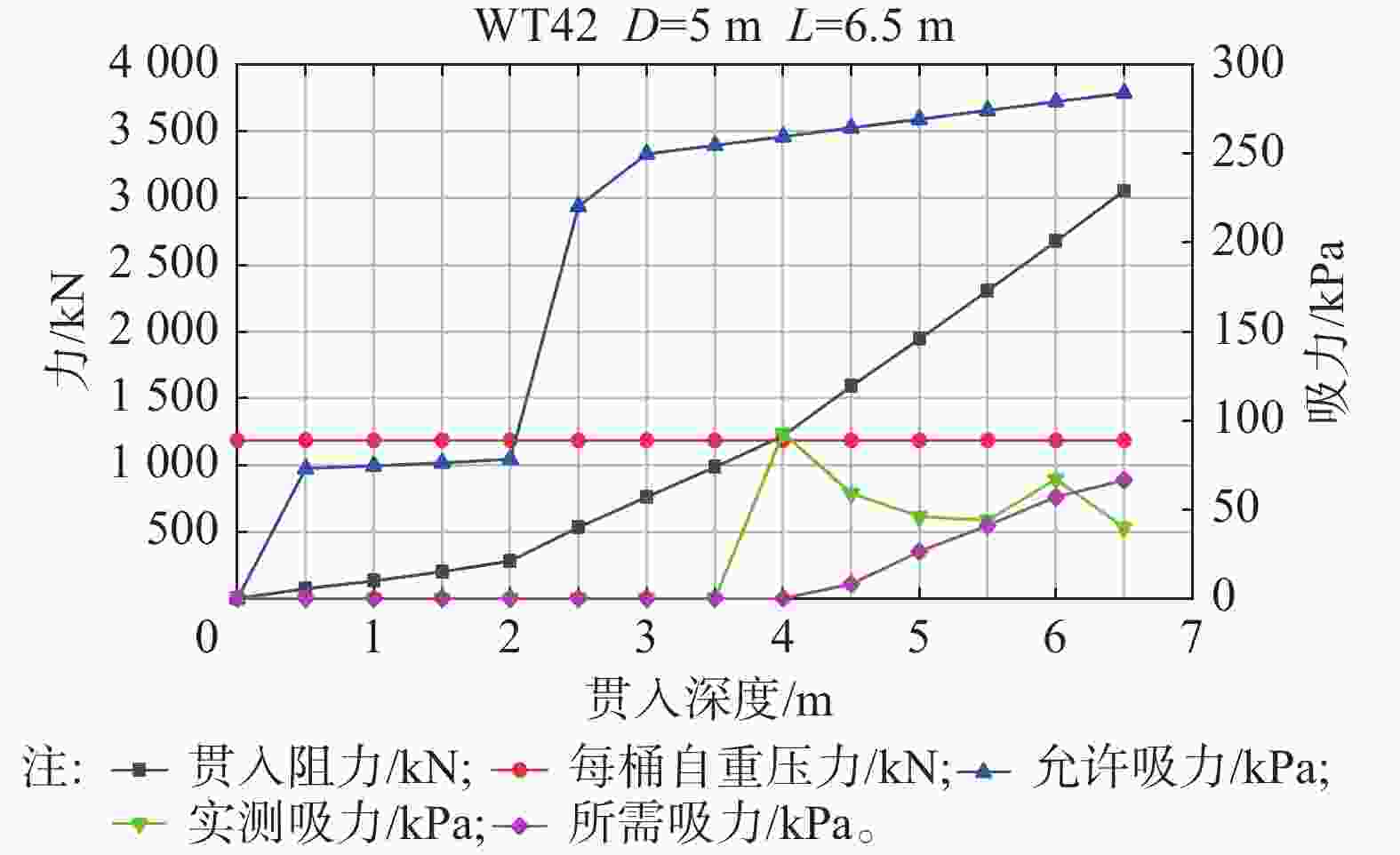
    Figure 5.  Penetration resistance and suction control curve

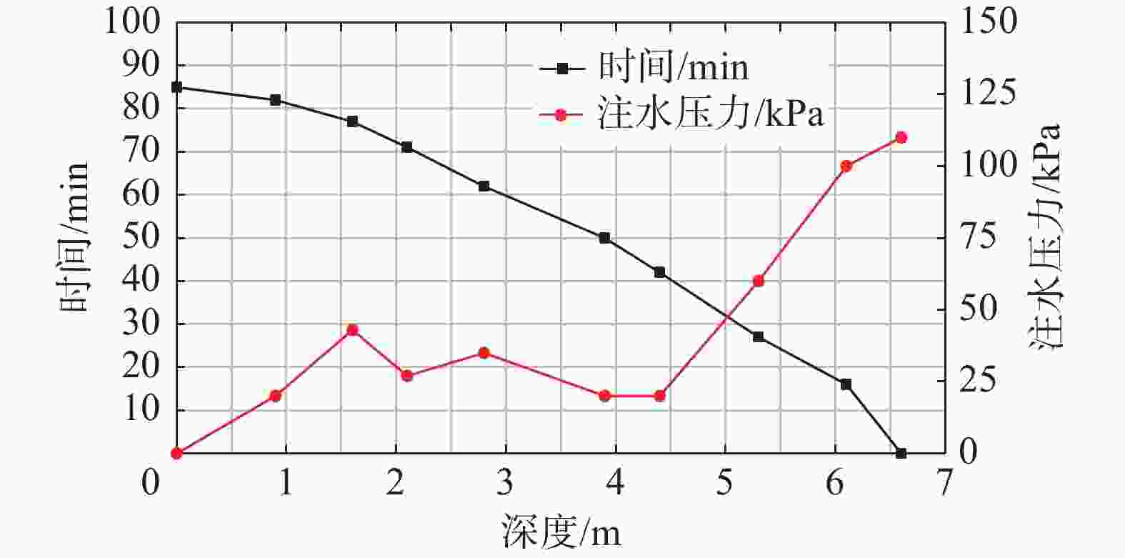
    Figure 6.  Jacking process curve of suction bucket

    图5所示控制曲线可以看出,在特定地质环境条件下,自重贯入深度一般3~4 m,达到设计贯入深度的50%~60%;实测贯入吸力围绕理论计算值上下波动,但距允许吸力还差一段距离,其冗余度与计算值基本一致。

    图6吸力桶顶升高度-时程曲线,吸力桶启动阶段用时较长,0~2 m段近40 min,平均速率3 cm/min,其余长度段速率约为9 cm/min。桶体启动压力最大,达到110 kPa,换算成顶升力约为2.355 MN,扣除吊机作用力与平台架重力,与理论计算值完全相符。

    2020年5月26日至2021年8月23日,47台导向架桩平台吸力桶基础使用这套计算分析方法与过程监测控制系统,通过调整吸力泵的压力,改变吸力桶下沉速度,保证平台倾斜角度始终在1°以内,有效地控制沉贯速度和质量,保证主体工程达到预期效果。

  • 本文以广东沿海某海上风电场导向架平台基础施工项目为背景,系统地介绍了吸力桶贯入/顶升可行性分析方法;给出施工过程控制参数、控制标准与控制技术、吸力桶状态参数的监测方法;探讨贯入阻力、上部结构荷载、负压以及负压有效作用面积之间的关系等吸力桶施工过程控制中的关键技术。工程实测数据表明,上述控制方法与相关技术标准,真实反映吸力桶基础施工过程中控制参数的变化特征,具有良好的控制效果。项目的成功实施,为丰富吸力桶应用数据库积累成功案例,为吸力桶基础进一步的推广应用奠定基础。

Reference (14)

Catalog

    /

    DownLoad:  Full-Size Img  PowerPoint
    Return
    Return