• Peer Review
  • Non-profit
  • Global Open Access
  • Green Channel for Rising Stars
Volume 10 Issue 1
Jan.  2023
Turn off MathJax
Article Contents

GUO Jiangtao, CHEN Shuo, HUANG Liling. Flexiable Fault Ride Through Capability Improvement of Semi-Direct Drive Wind Power System Based on Improved Grid-Side Control Strategy[J]. SOUTHERN ENERGY CONSTRUCTION, 2023, 10(1): 146-153. doi: 10.16516/j.gedi.issn2095-8676.2023.01.019
Citation: GUO Jiangtao, CHEN Shuo, HUANG Liling. Flexiable Fault Ride Through Capability Improvement of Semi-Direct Drive Wind Power System Based on Improved Grid-Side Control Strategy[J]. SOUTHERN ENERGY CONSTRUCTION, 2023, 10(1): 146-153. doi: 10.16516/j.gedi.issn2095-8676.2023.01.019

Flexiable Fault Ride Through Capability Improvement of Semi-Direct Drive Wind Power System Based on Improved Grid-Side Control Strategy

doi: 10.16516/j.gedi.issn2095-8676.2023.01.019
  • Received Date: 2021-12-27
  • Rev Recd Date: 2022-04-01
  • Available Online: 2022-12-22
  • Publish Date: 2023-01-11
  •   Introduction  In order to improve the flexible fault ride through (FFRT) capability of semi-direct drive wind power system, this paper proposes an improved grid-side control strategy with reactive power priority.   Method  Based on the analysis of the traditional grid side control strategy, reactive power priority control was added to the traditional grid side control according to the latest test rules of fault voltage ride through capability, and reactive current was injected into the grid to support the voltage recovery during the transient faults of the grid. According to the improved grid-side control strategy, the FFRT simulation operation of wind turbine was realized by using chopper circuits combined with the improved grid-side control strategy when the deep sag and rise of the grid was realized. Combined with the 6 MW semi-direct drive wind turbine of a certain project, the fault voltage ride field test was carried out by using mobile FFRT test equipment.   Results  The test and simulation results show that the improved grid-side control strategy can improve FFRT operation of semi-direct drive wind power system and stable control of reactive current.   Conclusion  The improved grid-side control strategy can give priority to injecting the corresponding stable reactive current into the grid under various symmetric low voltage/high voltage fault conditions and asymmetric high voltage fault conditions, which can assist the voltage recovery of the grid and improve the FFRT capacity of the semi-direct drive wind power system.
  • [1] 贺益康, 胡家兵, 徐烈. 并网双馈异步风力发电机运行控制 [M]. 北京: 中国电力出版社, 2012.

    HE Y K, HU J B, XU L. Operation control of doubly fed induction generator of wind turbine [M]. Beijing: China Electric Power Press, 2012.
    [2] 杨琳琳. 基于超级电容储能的直驱风机故障穿越和频率调节控制 [D]. 北京: 华北电力大学(北京), 2021. DOI: 10.27140/d.cnki.ghbbu.2021.000429.

    YANG L L. Research on fault ride through and frequency regulation of PMSG-based wind turbine generator based on the supercapacitor energy storage [D]. Beijing: North China Electric Power University (Beijing), 2021. DOI: 10.27140/d.cnki.ghbbu.2021.000429.
    [3] 傅伯雄. 风力发电并网低/高电压穿越技术的研究 [D]. 石家庄: 河北科技大学, 2015.

    FU B X. Research on wind turbine low/high voltage ride through [D]. Shijiazhuang: Hebei University of Science & Technology, 2015.
    [4] 王海鑫, 杨俊友, 李欣, 等. 电网故障下直驱永磁风力发电机组机侧变流器改进控制策略 [J]. 可再生能源, 2015, 33(11): 1632-1639. DOI:  10.13941/j.cnki.21-1469/tk.2015.11.007.

    WANG H X, YANG J Y, LI X, et al. Improved machine-side converter control strategy of direct-drive permanent magnet synchronous generator for wind power system during grid failures [J]. Renewable Energy, 2015, 33(11): 1632-1639. DOI:  10.13941/j.cnki.21-1469/tk.2015.11.007.
    [5] 杨艺云, 肖静, 张阁, 等. 永磁直驱风机低电压穿越协调控制策略 [J]. 电气传动, 2017, 47(7): 43-49. DOI:  10.19457/j.1001-2095.20170709.

    YANG Y Y, XIAO J, ZHANG G, et al. Coordinated low voltage ride through control strategy for permanent magnet direct drive wind turbine [J]. Electric Drive, 2017, 47(7): 43-49. DOI:  10.19457/j.1001-2095.20170709.
    [6] 李和明, 董淑惠, 王毅, 等. 永磁直驱风电机组低电压穿越时的有功和无功协调控制 [J]. 电工技术学报, 2013, 28(5): 73-81. DOI:  10.19595/j.cnki.1000-6753.tces.2013.05.010.

    LI H M, DONG S H, WANG Y, et al. Coordinated control of active and reactive power of PMSG-based wind turbines for low voltage ride through [J]. Transactions of China Electrotechnical Society, 2013, 28(5): 73-81. DOI:  10.19595/j.cnki.1000-6753.tces.2013.05.010.
    [7] 王敏, 周羽生, 杨航, 等. 基于SMES-SFCL直驱永磁风电并网故障穿越能力 [J]. 电力系统及其自动化学报, 2022, 34(10): 138-144. DOI:  10.19635/j.cnki.csu-epsa.000861.

    WANG M, ZHOU Y S, YANG H, et al. Fault through capability of direct drive permanent magnet wind power generation connected to grid based on SMES-SFCL [J]. Proceedings of the CSU-EPSA, 2022, 34(10): 138-144. DOI:  10.19635/j.cnki.csu-epsa.000861.
    [8] WEN G, CHEN Y, ZHONG Z H, et al. Dynamic voltage and current assignment strategies of nine-switch-converter-based DFIG wind power system for low-voltage ride-through (LVRT) under symmetrical grid voltage dip [J]. IEEE Transactions on Industry Applications, 2016, 52(4): 3422-3434. DOI:  10.1109/TIA.2016.2535274.
    [9] 李朋宇, 何山, 王松, 等. 直驱风机HVRT两种直流侧卸荷方法对比仿真研究 [J]. 电测与仪表, 2018, 55(22): 7-12. DOI:  10.3969/j.issn.1001-1390.2018.22.002.

    LI P Y, HE S, WANG S, et al. Comparative simulation analysis of PMSG HVRT on two different choppers [J]. Electrical Measurement & Instrumentation, 2018, 55(22): 7-12. DOI:  10.3969/j.issn.1001-1390.2018.22.002.
    [10] 任永峰, 胡宏彬, 薛宇, 等. 基于卸荷电路和无功优先控制的永磁同步风力发电机组低电压穿越研究 [J]. 高电压技术, 2016, 42(1): 11-18. DOI:  10.13336/j.1003-6520.hve.2016.01.002.

    REN Y F, HU H B, XUE Y, et al. Low voltage ride-through capability improvement of PMSG based on chopper circuit and reactive priority control [J]. High Voltage Engineering, 2016, 42(1): 11-18. DOI:  10.13336/j.1003-6520.hve.2016.01.002.
    [11] 代林旺, 秦世耀, 王瑞明, 等. 直驱永磁同步风电机组高电压穿越技术研究与试验 [J]. 电网技术, 2018, 42(1): 147-154. DOI:  10.13335/j.1000-3673.pst.2017.2077.

    DAI L W, QIN S Y, WANG R M, et al. Research and experiment on high voltage ride through for direct-drive PMSG-based wind turbines [J]. Power System Technology, 2018, 42(1): 147-154. DOI:  10.13335/j.1000-3673.pst.2017.2077.
    [12] 卢一菲, 陈冲, 金成日, 等. 直驱永磁风电机组高电压穿越协调控制策略 [J]. 电力系统保护与控制, 2020, 48(15): 50-60. DOI:  10.19783/j.cnki.pspc.190427.

    LU Y F, CHEN C, JIN C R, et al. HVRT coordinated control strategy of a direct-driven PMSG [J]. Power System Protection and Control, 2020, 48(15): 50-60. DOI:  10.19783/j.cnki.pspc.190427.
    [13] 张谦, 李凤婷, 蒋永梅, 等. 提高直驱永磁风机低电压穿越能力的控制策略 [J]. 电力系统保护与控制, 2017, 45(6): 62-67. DOI:  10.7667/PSPC160432.

    ZHANG Q, LI F T, JIANG Y M, et al. Comprehensive control strategy for improving low voltage ride through capability of permanent magnet synchronous generator [J]. Power System Protection and Control, 2017, 45(6): 62-67. DOI:  10.7667/PSPC160432.
    [14] 张谦, 李凤婷, 蒋俊凤. 一种PMSG低电压穿越综合控制策略 [J]. 电力电容器与无功补偿, 2016, 37(4): 123-129. DOI:  10.14044/j.1674-1757.pcrpc.2016.04.023.

    ZHANG Q, LI F T, JIANG J F. Integrated control strategy for a kind of low voltage ride through of PMSG [J]. Power Capacitor & Reactive Power Compensation, 2016, 37(4): 123-129. DOI:  10.14044/j.1674-1757.pcrpc.2016.04.023.
    [15] 陈烁, 唐彬伟, 郭江涛, 等. 基于GSNSC的风电系统故障穿越能力研究 [J]. 电器与能效管理技术, 2022(9): 26-31. DOI:  10.16628/j.cnki.2095-8188.2022.09.004.

    CHEN S, TANG B W, GUO J T, et al. Research on GSNSC based fault ride through capability of wind power system [J]. Electrical Appliances and Energy Efficiency Management Technology, 2022(9): 26-31. DOI:  10.16628/j.cnki.2095-8188.2022.09.004.
    [16] 李辉, 杨甜, 胡玉, 等. 基于模型预测控制的机侧变流器功率模块结温波动抑制策略 [J]. 太阳能学报, 2022, 43(3): 455-461. DOI:  10.19912/j.0254-0096.tynxb.2020-0498.

    LI H, YANG T, HU Y, et al. Junction temperature fluctuation suppression strategy for power module of turbine side converter based on model predictive control [J]. Journal of Solar Energy, 2022, 43(3): 455-461. DOI:  10.19912/j.0254-0096.tynxb.2020-0498.
    [17] HEYDARI M, VARJANI A Y, MOHAMADIAN M, et al. A novel variable-speed wind energy system using permanent-magnet synchronous generator and nine-switch AC/AC converter [C]// IEEE. Power Electronics. Drive Systems & Technologies Conference, Tehran, Iran, 2011. Tehran, Iran: IEEE, 2011. DOI: 10.1109/PEDSTC.2011.5742490.
    [18] 陈烁, 任永峰, 薛宇, 等. 基于SVPWM的直驱永磁同步风电系统GS-NSC研究 [J]. 可再生能源, 2020, 38(9): 1210-1216. DOI:  10.13941/j.cnki.21-1469/tk.2020.09.013.

    CHEN S, REN Y F, XUE Y, et al. Study on permanent magnet synchronous wind power system GS-NSC based on SVPWM [J]. Renewable Energy, 2020, 38(9): 1210-1216. DOI:  10.13941/j.cnki.21-1469/tk.2020.09.013.
    [19] 中国机械工业联合会. 风力发电机组 故障电压穿越能力测试规程: GB/T 36995—2018 [S]. 北京: 中国标准出版社, 2018.

    China Machinery Industry Federation. Wind turbines-test procedure of voltage fault ride through capability [S]. Beijing: Standards Press of China, 2018.
  • 通讯作者: 陈斌, bchen63@163.com
    • 1. 

      沈阳化工大学材料科学与工程学院 沈阳 110142

    1. 本站搜索
    2. 百度学术搜索
    3. 万方数据库搜索
    4. CNKI搜索

Figures(10)  / Tables(1)

Article Metrics

Article views(125) PDF downloads(32) Cited by()

Related

Flexiable Fault Ride Through Capability Improvement of Semi-Direct Drive Wind Power System Based on Improved Grid-Side Control Strategy

doi: 10.16516/j.gedi.issn2095-8676.2023.01.019

Abstract:   Introduction  In order to improve the flexible fault ride through (FFRT) capability of semi-direct drive wind power system, this paper proposes an improved grid-side control strategy with reactive power priority.   Method  Based on the analysis of the traditional grid side control strategy, reactive power priority control was added to the traditional grid side control according to the latest test rules of fault voltage ride through capability, and reactive current was injected into the grid to support the voltage recovery during the transient faults of the grid. According to the improved grid-side control strategy, the FFRT simulation operation of wind turbine was realized by using chopper circuits combined with the improved grid-side control strategy when the deep sag and rise of the grid was realized. Combined with the 6 MW semi-direct drive wind turbine of a certain project, the fault voltage ride field test was carried out by using mobile FFRT test equipment.   Results  The test and simulation results show that the improved grid-side control strategy can improve FFRT operation of semi-direct drive wind power system and stable control of reactive current.   Conclusion  The improved grid-side control strategy can give priority to injecting the corresponding stable reactive current into the grid under various symmetric low voltage/high voltage fault conditions and asymmetric high voltage fault conditions, which can assist the voltage recovery of the grid and improve the FFRT capacity of the semi-direct drive wind power system.

GUO Jiangtao, CHEN Shuo, HUANG Liling. Flexiable Fault Ride Through Capability Improvement of Semi-Direct Drive Wind Power System Based on Improved Grid-Side Control Strategy[J]. SOUTHERN ENERGY CONSTRUCTION, 2023, 10(1): 146-153. doi: 10.16516/j.gedi.issn2095-8676.2023.01.019
Citation: GUO Jiangtao, CHEN Shuo, HUANG Liling. Flexiable Fault Ride Through Capability Improvement of Semi-Direct Drive Wind Power System Based on Improved Grid-Side Control Strategy[J]. SOUTHERN ENERGY CONSTRUCTION, 2023, 10(1): 146-153. doi: 10.16516/j.gedi.issn2095-8676.2023.01.019
    • 半直驱永磁同步风电系统(Semi-Direct Drive Permanent Magnet Synchronous Generator,PMSG)兼具直驱风电系统可靠性和双馈风电系统结构紧凑的优势,半直驱永磁同步风电系统与直驱风电系统和双馈风电系统的主要区别在于发电机和齿轮箱,半直驱永磁同步系统发电机采用中速永磁同步发电机,与直驱风电系统相比,在体积和重量上小了很多。半直驱永磁同步风电系统采用中速齿轮箱,与双馈风电系统的高速齿轮箱相比,降低了故障率及设计成本,提高了发电效率,同时保留了永磁同步发电机系统优良的FFRT能力,是风力发电的主流方向之一[1-3]

      半直驱风电系统通过全功率变换器与电网解耦,具有优越的FFRT能力。目前增强FFRT功能的方法主要集中以下两方面:(1)从改变机侧控制策略的角度出发,在电网故障时通过限制风机桨距角,控制输入至电网的功率实现了风电系统的低电压穿越。这种方法增加了机侧控制策略的难度,且存在响应及时性的问题[4-6];(2)采用卸荷电路或储能系统[7-9]在故障期间稳定直流侧电压,但在故障期间未向电网注入无功电流,不满足国标要求。为提高风电系统FFRT能力,文献[10]采用卸荷电路与改进网侧控制策略相结合的方式实现了风电系统的低电压穿越,但并未对高电压穿越能力进行验证。文献[11-12]提出了基于动态无功电流控制的高电压穿越控制策略,实现了风电系统高穿期间稳定控制。文献[13-14]采用变阻值卸荷电阻可在低电压穿越期间卸放更多能量,实现低电压穿越期间的稳定控制。

      本文采用无功优先的改进网侧控制策略结合卸荷电路,可提升半直驱风电系统的FFRT能力。系统整体拓扑结构如图1所示。卸荷电路主要在电网电压故障期间维持直流侧电容功率稳定,网侧变换器在稳态时维持直流侧电压稳定,在故障期间优先向电网注入无功电流。仿真与实测结果表明,采用的控制策略可在多种电网电压故障时,优先向电网注入无功电流支撑电网电压恢复。

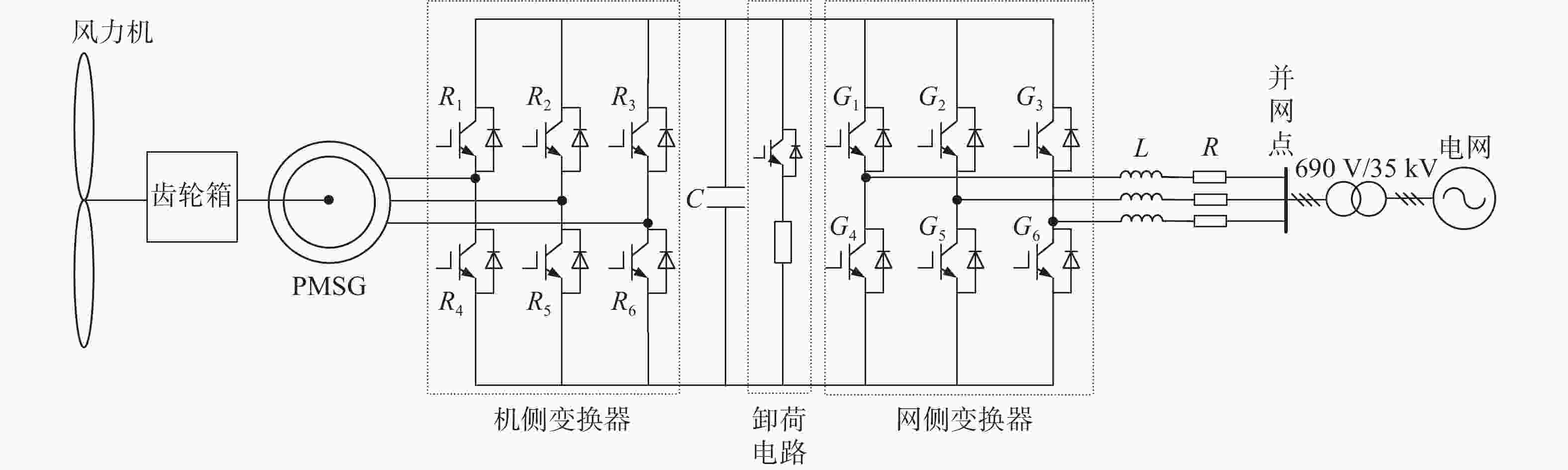
      Figure 1.  Topological structure of semi-direct drive wind power system

    • 机侧变换器的控制本质上是对发电机组的控制[15-16],实现对风电机组的功率控制。本文的机侧变换器采用转速外环和电流内环的双闭环控制策略[17],转速外环的给定值是控制目标实现的关键。其中转速外环的转速给定由主控给出。PMSG在dq旋转坐标系下的电压方程为:

      $$ \left\{ \begin{gathered} {u_{{\text{s}}d}} = {R_{\text{s}}}{i_{{\text{s}}d}} + {L_{d}}\dfrac{{{\text{d}}{i_{{\text{s}}d}}}}{{{{\rm{d}}}t}} - {\omega _{\text{s}}}{L_{q}}{i_{{\text{s}}q}} \\ {u_{{\text{s}}q}} = {R_{\text{s}}}{i_{{\text{s}}q}} + {L_{q}}\dfrac{{{\text{d}}{i_{{\text{s}}q}}}}{{{\text{d}}t}} + {\omega _{\text{s}}}{L_d}{i_{{\text{s}}d}} + {\omega _{\text{s}}}{\psi _{\rm{f}}} \\ \end{gathered} \right. $$ (1)

      式中:

      LdLq ——定子电感dq轴分量(H);

      ψf ——转子磁链(Wb);

      usdusq——定子电压dq轴分量(V);

      isdisq ——定子电流dq轴分量(A);

      ωs ——同步角速度(rad/s);

      Rs ——电网内阻(Ω)。

    • 网侧变换器的主要目标为在理想电网条件下维持直流侧电压稳定[18],同时在电网电压暂态故障时优先向电网注入无功电流辅助电网电压恢复。网侧变换器控制多采用直流电压外环和电流内环的双闭环控制方式。为实现功率解耦控制,将电网电压矢量定向于d轴,则d轴电流控制有功功率,q轴电流控制无功功率,得出网侧变换器在dq旋转坐标系下的电压方程为:

      $$ \left\{ \begin{gathered} {u_{{\text{g}}d}} = - {R_{\text{g}}}{i_{{\text{g}}d}} - {L_{\text{g}}}\dfrac{{{\text{d}}{i_{{\text{g}}d}}}}{{{\text{d}}t}} + {\omega _{\text{g}}}{L_{\text{g}}}{i_{{\text{g}}q}} + {v_{{\text{g}}d}} \\ {u_{{\text{g}}q}} = - {R_{\text{g}}}{i_{{\text{g}}q}} - {L_{\text{g}}}\dfrac{{{\text{d}}{i_{{\text{g}}q}}}}{{{\text{d}}t}} - {\omega _{\text{g}}}{L_{\text{g}}}{i_{{\text{g}}d}} + {v_{{\text{g}}q}} \\ \end{gathered} \right. $$ (2)

      式中:

      Rg ——线路电阻(Ω);

      Lg ——滤波器电感(H);

      ωg ——电网同步旋转角速度(rad/s);

      ugdugq——网侧变换器电压的dq轴分量(V);

      igdigq ——网侧变换器电流的dq轴分量(A);

      vgdvgq ——电网电压的dq轴分量(V)。

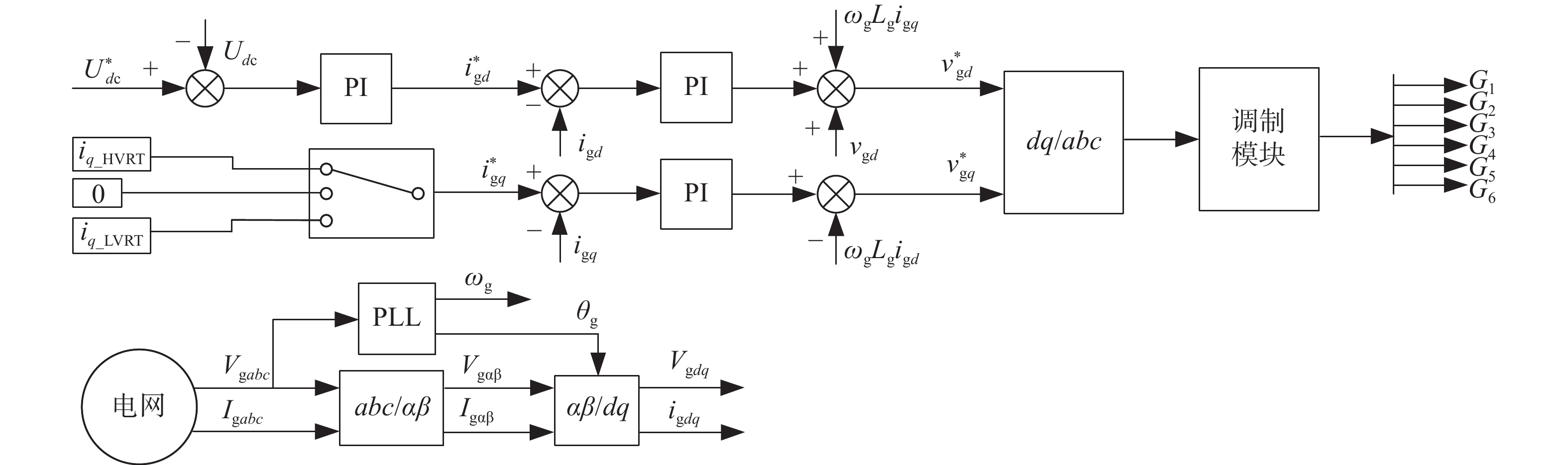
      根据我国最新《风力发电机组 故障电压穿越能力测试规程》(GB/T 36995—2018)要求:在电网电压故障期间,风电系统按要求需向电网优先注入一定的无功电流支撑电网电压恢复[19]。常规网侧双闭环控制无法满足国标要求,对网侧变换器控制策略进行优化,其优化后的控制策略如图2所示。其中,优化后在故障期间无功电流给定分为三个通道:上通道为高电压穿越运行模式,下通道为低电压穿越运行模式,中间通道为单位功率因数运行模式,在该模式下,其无功电流给定iq=0。

      Figure 2.  Control strategy of grid-side converter

      其无功电流给定由下式给出:

      $$\left\{ \begin{split} & {{i}_{\text{g}\_\text{HVRT}}}=1.5\times \left( {{U}_{\text{T}}}-1.1 \right){{I}_{\text{n}}}\;\;\;\; 1.1\leqslant {{U}_{\text{T}}}\leqslant 1.3 \\ & {{i}_{\text{g}\_\text{LVRT}}}=1.5\times \left( 0.9-{{U}_{\text{T}}} \right){{I}_{\text{n}}}\;\;\;\; 0.2\leqslant {{U}_{\text{T}}}\leqslant 0.9 \\ \end{split} \right.$$ (3)

      式中:

      ig_HVRT——高电压穿越期间无功电流给定(A);

      ig_LVRT——低电压穿越期间无功电流给定(A);

      UT ——并网点电压标幺值(pu);

      In ——风电系统额定电流(A)。

    • 低电压穿越运行过程中,由于并网点电压(Point of Common Connection,PCC)跌落,由直流侧传输至电网的功率减小,考虑全功率变换器机网侧解耦特性,机侧功率在故障期间正常工作,势必造成机网侧功率不平衡,多余功率囤积在直流侧电容造成直流侧电压骤升;高电压穿越运行过程中,由于并网点电压升高,电网能量会通过反并联二极管倒灌至直流侧一部分导致直流侧电压骤升;为维持故障穿越期间直流侧电压的稳定,在故障穿越期间投入卸荷电路,消耗直流侧多余的能量,抑制直流侧过电压,进而实现风电系统FFRT运行。

      卸荷电阻阻值大小取决于需要消耗的最大功率及直流侧允许的最高电压。当不考虑回路中的非线性元件时,其卸荷电阻取值为:

      $$ R=\dfrac{U_{\text{dc } \_ \text{ }\max }^{\text{2}}}{{\mathit{\Delta }} P} $$ (4)
      $$ {\mathit{\Delta }} P=\dfrac{1}{2}C\frac{\text{d}(U_{\text{dc } \_ \text{ }\max }^{\text{2}})}{\text{d}t} $$ (5)

      式中:

      Udc_max——直流侧电压最大值(V);

      ${\mathit{\Delta }}P $ ——需要消耗的最大功率(W);

      C ——直流电容容值(F)。

      根据系统参数及故障电压穿越过程中有功功率变化量,综合可得卸荷电阻阻值R=0.5 Ω。

    • 为验证改进网侧控制策略提升半直驱风电系统FFRT能力,建立半直驱风电系统仿真模型;并在某项目现场进行实测,其风电系统参数如表1所示。

      名 称参 数
      风机额定容量/MW 6
      机组额定电流/A 5 285
      额定风速/(cm·s−1 11
      齿轮箱增速比 23.2
      PMSG直轴电感/mH 0.151
      PMSG交轴电感/mH 0.200
      直流侧电压/kV 1.1

      Table 1.  Parameters of semi-direct drive wind power system

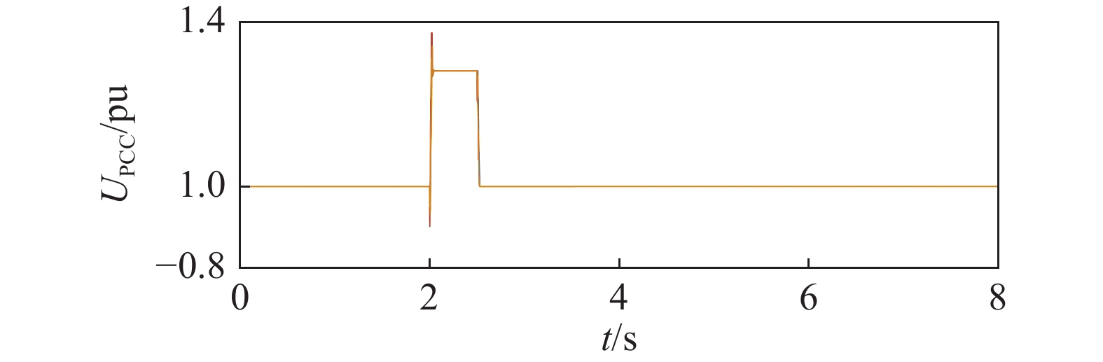
    • 为验证半直驱风电系统的高电压穿越能力,仿真设计风速条件为风电机组的额定风速11 m/s保持不变。其空载、实测及仿真数据如图3图4所示。其中实测数据为蓝色曲线,仿真数据为红色曲线(其它工况相同)。

      Figure 3.  3-phase 130% no-load voltage

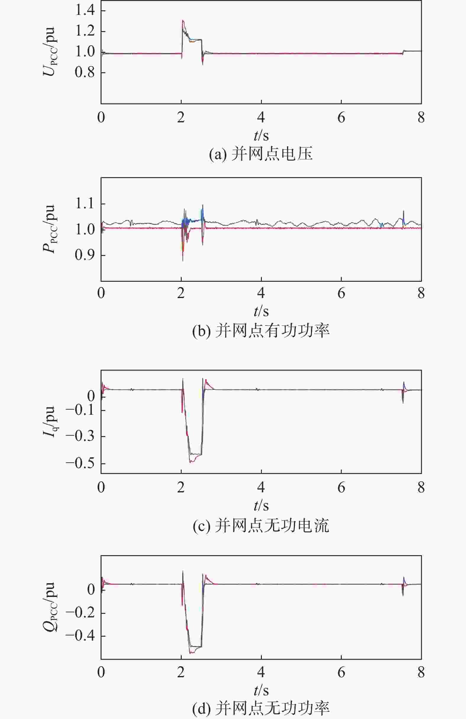
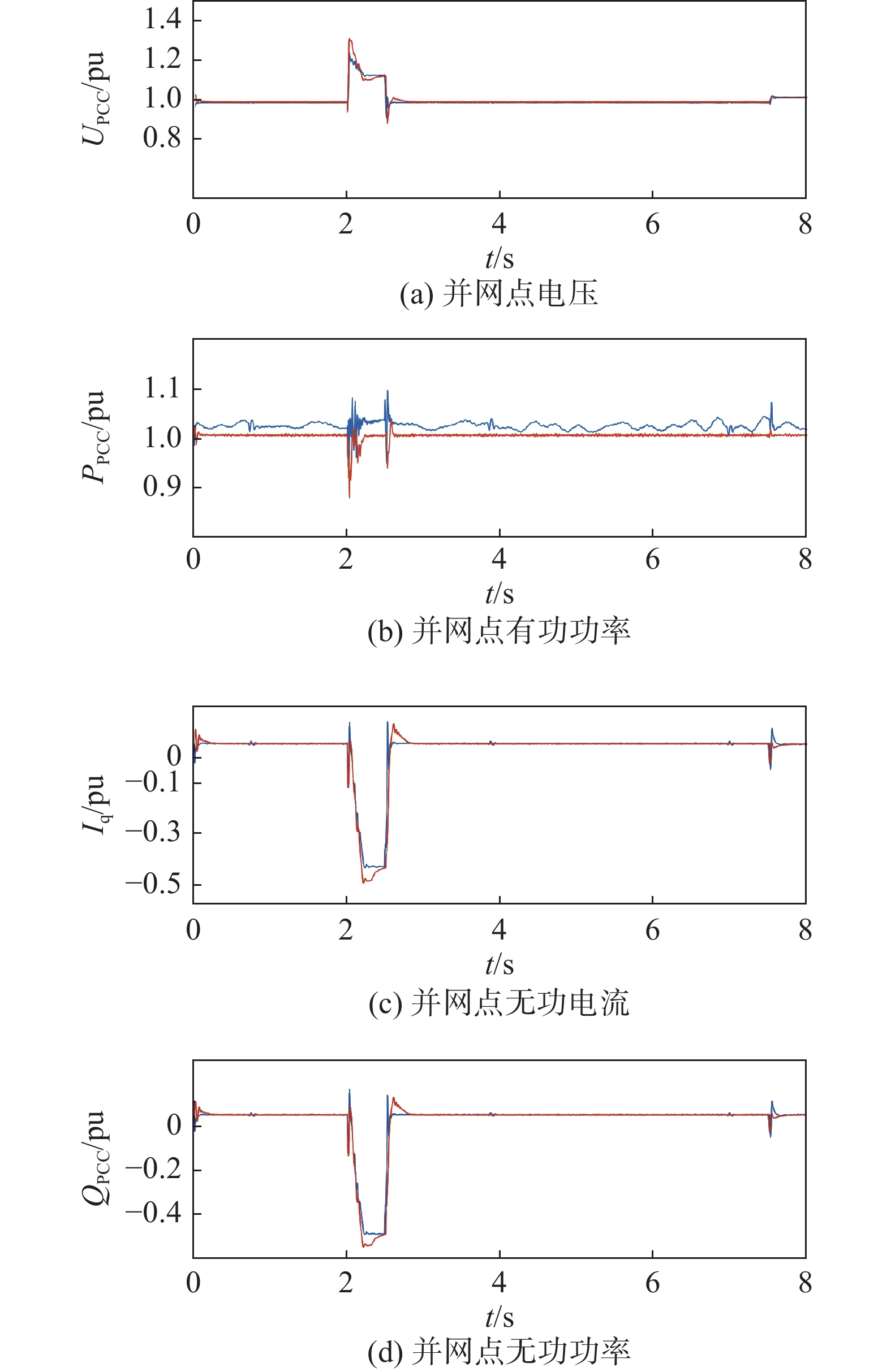
      Figure 4.  Measured and simulated waveforms of symmetric high voltage ride through

      根据新测试规程要求,将测试参数导入仿真模型中,其空载电压如图3所示,在空载期间其空载抬升电压约为1.281 pu,在标准要求±3%内。

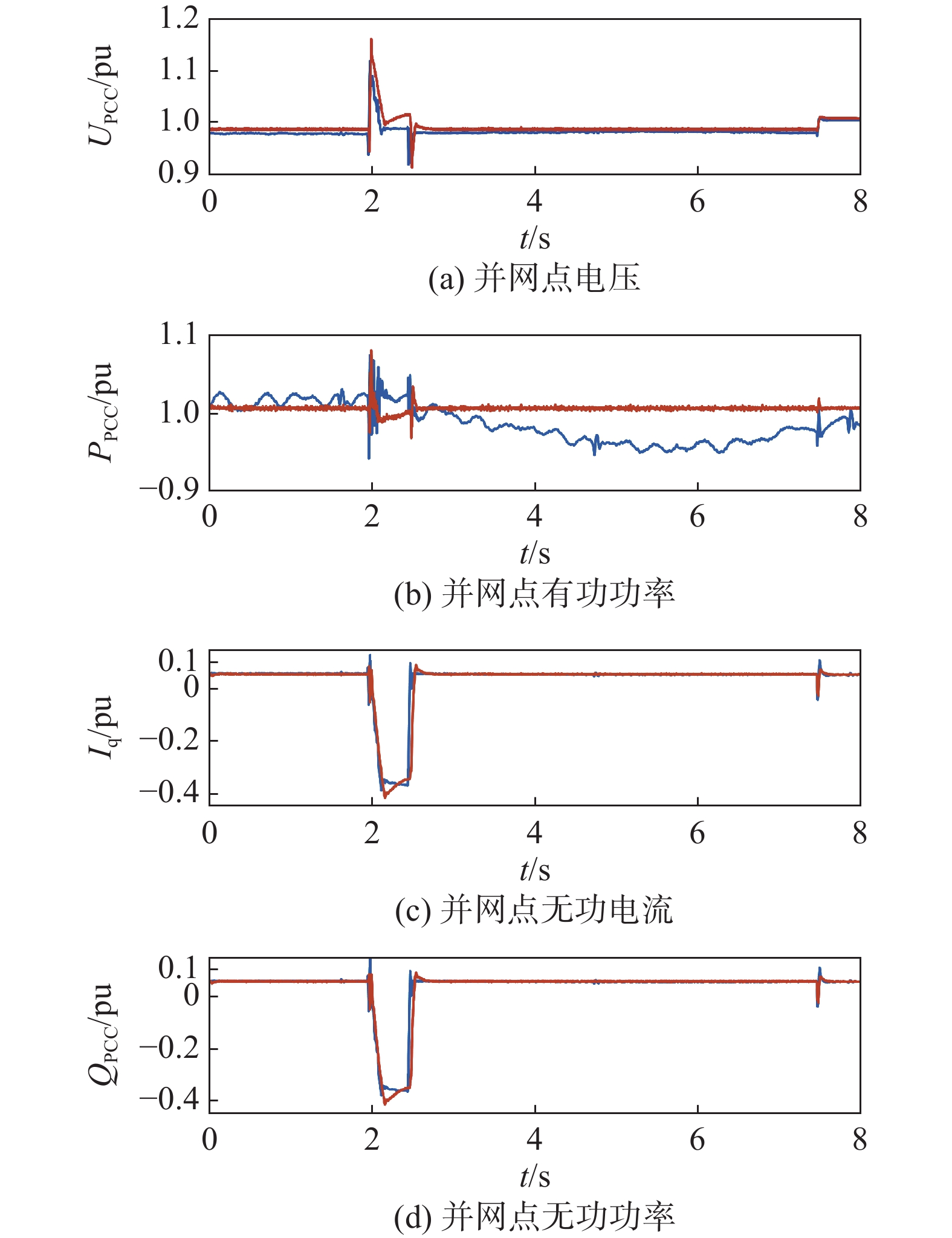
      电网电压对称骤升至130%工况时,风电机组应优先向电网注入感性无功电流支撑电网电压恢复。为与实测数进行对比分析,模拟在2.0~2.5 s时并网点电压UPCC对称升高至130%的工况,其测试及仿真对比结果如图4所示。在电压骤升工况下,从波形可以看出实测和仿真分别向风电机组优先发出0.430 pu及0.460 pu左右的感性无功电流,高于其理论值0.300 pu,且其响应时间约为20 ms,可以更快响应电压变化,有利于UPCC恢复;此时由于无功电流的作用,电压由理论值1.280 pu降为1.130 pu左右。无功电流响应时间约为20 ms,不超标准要求的40 ms,无功电流控制良好。根据其有功功率波形可以看出,实测时由于风速实时变化,其功率呈现不规则波动,仿真波形由于风速固定则相对平滑,均在高穿开始及结束时刻有较大暂态波动。在整个高电压穿越运行期间,网侧变换器优先向电网注入无功电流支撑电网电压恢复,实现了半直驱风电系统的高电压穿越运行。

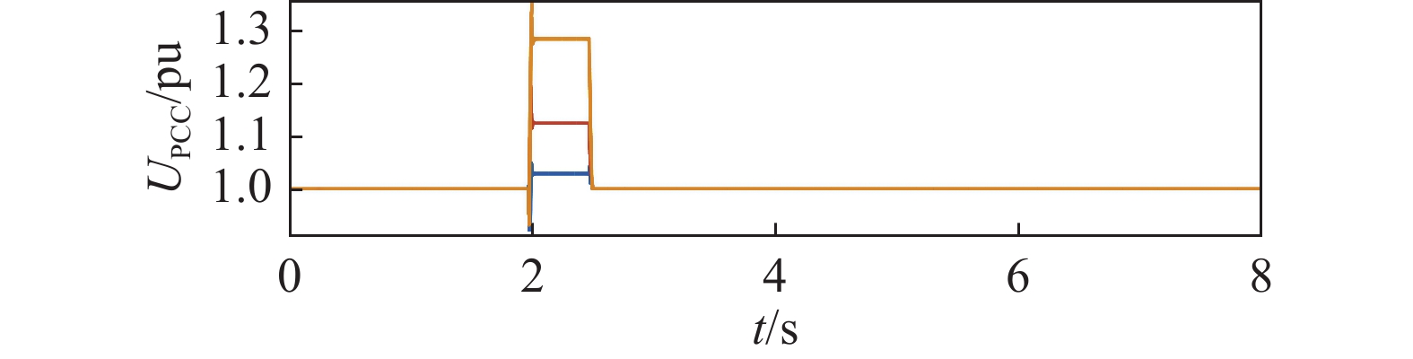
    • 为验证半直驱风电系统不对称高电压穿越能力,在3.1的基础上,设计AC两相对称升高,其空载波形如图5所示。

      Figure 5.  2-phase 130% no-load voltage

      根据图6可看出,在不对称高电压穿越期间,风电机组在实测和仿真中分别通过网侧变换器优先向电网注入约0.361 pu和0.369 pu的无功电流支撑电网电压由1.140 pu降低至约1.014 pu,无功电流响应时间约20 ms,比标准要求快一倍左右,无功电流作用效果明显。根据PPCC波形可以看出,在高穿故障结束后约3 s,其功率由于风速减小呈现跌落趋势,风速恢复后,又随之增大;在高穿开始和结束时刻,有功功率有约为0.080 pu的暂态波动。整个不对称高电压船业运行期间,网侧变换器优先向电网注入无功电流支撑电网电压恢复,实现了风电系统的柔性不对称高电压穿越运行。

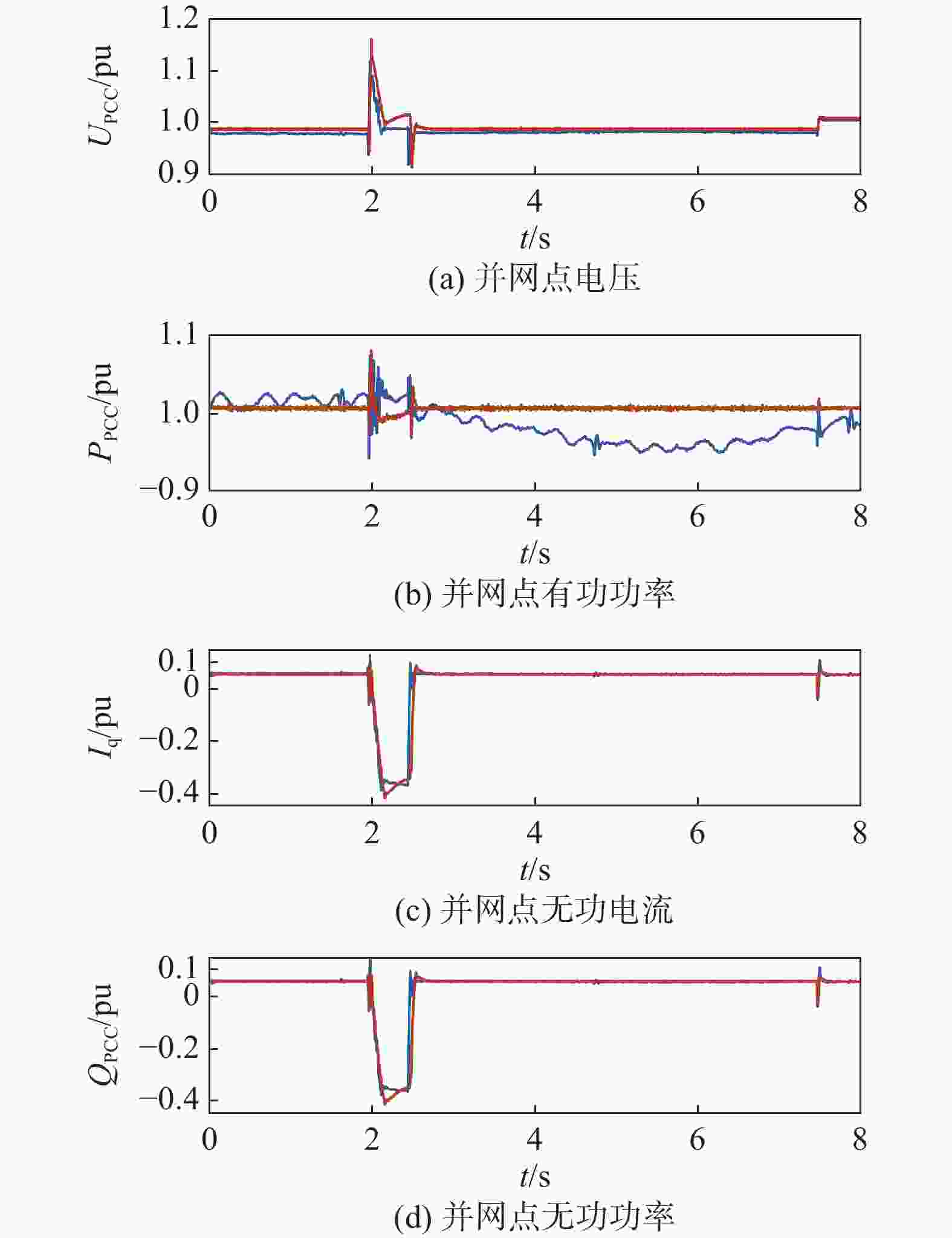
      Figure 6.  Measured and simulated waveforms of asymmetric low voltage ride through

    • 为验证半直驱风电系统对称低电压穿越能力,仿真风速保持不变,其空载电压波形如图7所示。在故障期间,其故障电压跌落至0.220 pu,标准要求电压跌落档位偏差为(0.200±0.050) pu,在标准要求内。

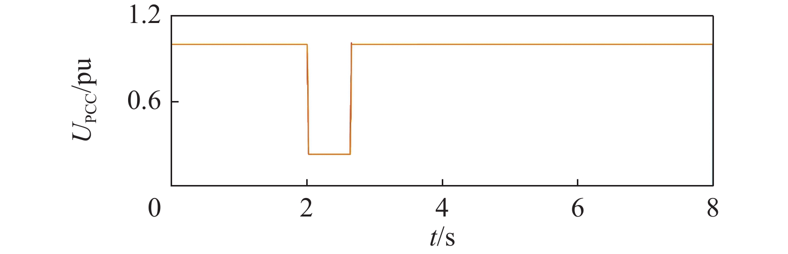
      Figure 7.  3-phase 20% no-load voltage

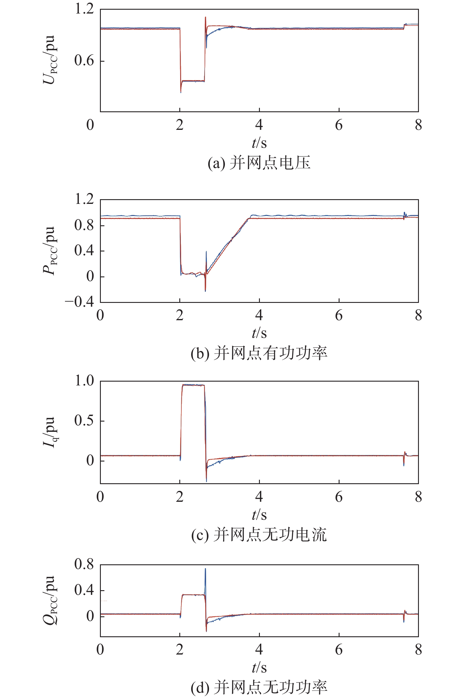
      电网电压对称跌落80%工况时,应优先向电网注入容性无功功率支撑电压恢复。为对比实测和仿真结果,仿真设计在2.000~2.625 s时发生三相对称20%跌落工况,其测试和仿真结果分析对比如图8所示。从实测和仿真波形图可以看出,在整个低电压穿越期间风电系统向并网点注入约0.955 pu和0.944 pu左右的无功电流,其响应时间约为46 ms,响应速度远快于标准要求的75 ms,符合标准要求。在无功电流支撑下,UPCC从其空载的0.220 pu抬升至0.355 pu。

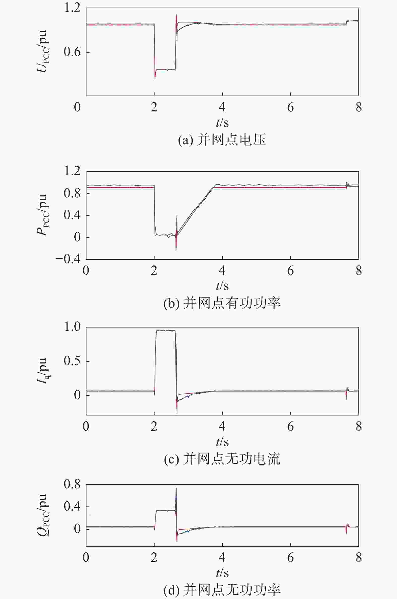
      Figure 8.  Measured and simulated waveforms of symmetric low voltage ride through

      无功电流作用效果明显。整个故障期间,向电网注入约0.050 pu的有功功率,其余0.950 pu的能量均通过卸荷电阻以热能的形式释放,在故障结束时刻出现较大暂态波动。故障结束后有功功率恢复期间,其恢复速率在实测工况下维持约72.5%Pn/s的速率恢复,仿真期间维持约81.5%Pn/s的速率恢复,远快于标准要求的10%Pn/s,风电系统控制性能良好。仿真和实测无功功率基本维持在0.340 pu左右,仅实测波形在故障结束时刻有0.200 pu左右的暂态波动。在整个对称低电压穿越期间,网侧变换器优先向电网注入无功电流支撑并网点电压,实现了半直驱风电系统对称低电压穿越。

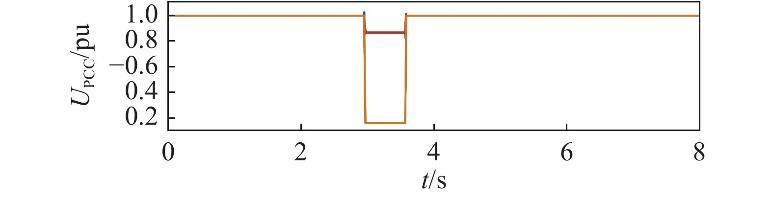
    • 为验证半直驱风电系统在不对称电压故障下的运行能力,设计并网点发生AC两相短路故障,其故障空载电压如图9所示,可看出在故障期间,线电压跌落最深相跌落至0.164 pu,符合标准。

      Figure 9.  2-Phase 20% no-load voltage

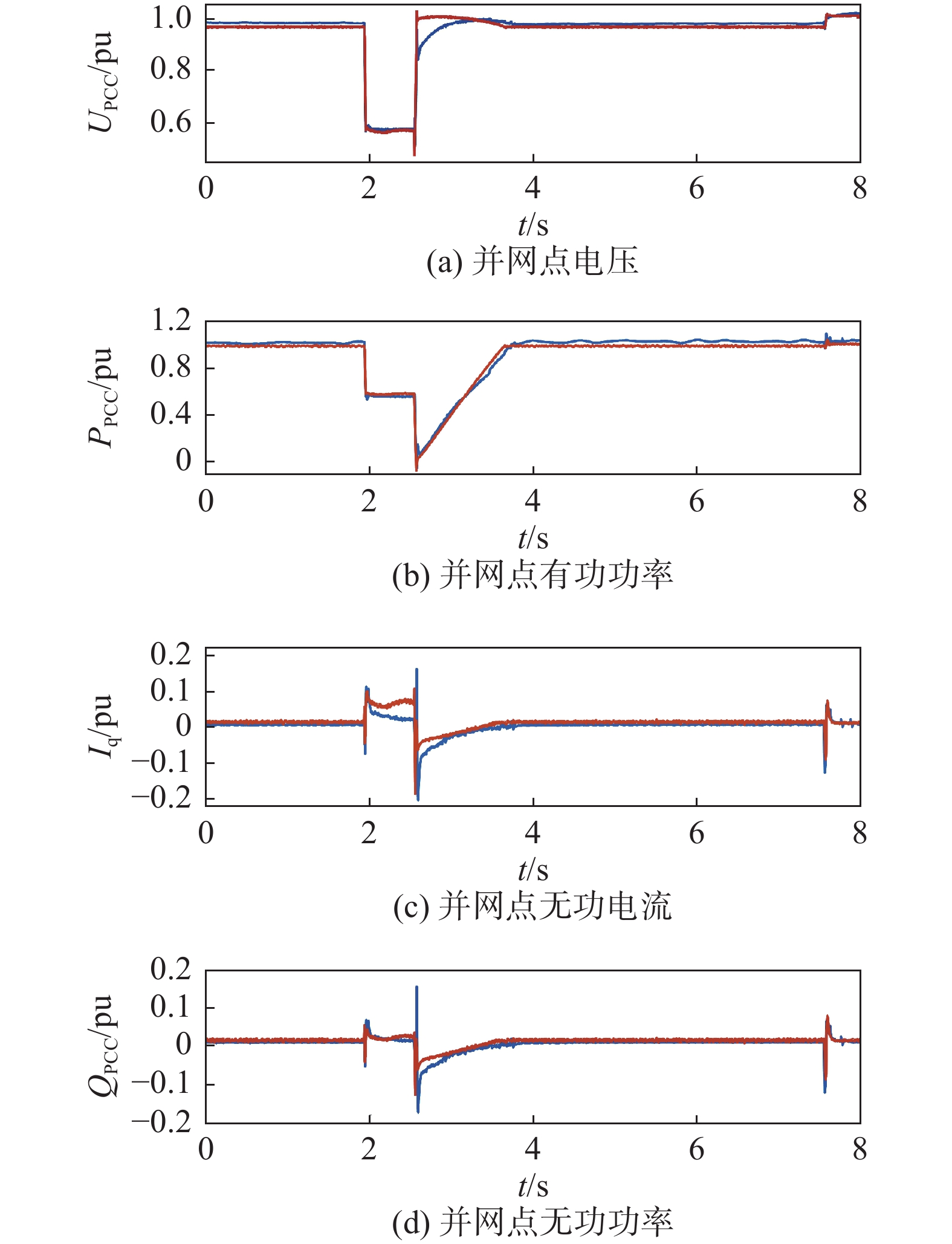
      实测和仿真数据的正序分量波形如图10所示。由于不对称期间,标准对无功电流不做要求,为简化控制,在不对称期间网侧变换器不发无功电流支撑电网电压,从图10中的Iq波形可以看出。在故障期间,由于卸荷电路的作用,并网点有功功率PPCC比故障前时刻略低,在故障结束后的恢复阶段,实测和仿真分别以85%Pn/s和91%Pn/s的速率恢复至当前风速对应功率。在故障期间,其正序电压在故障结束时刻有微小的暂态波动;其中无功电流Iq和无功功率QPCC在故障开始和结束时刻有不到0.100 pu幅度的暂态波动,整个实测和仿真期间,网侧变换器控制良好,风机稳定运行,实现了半直驱风电系统的不对称低电压穿越运行。

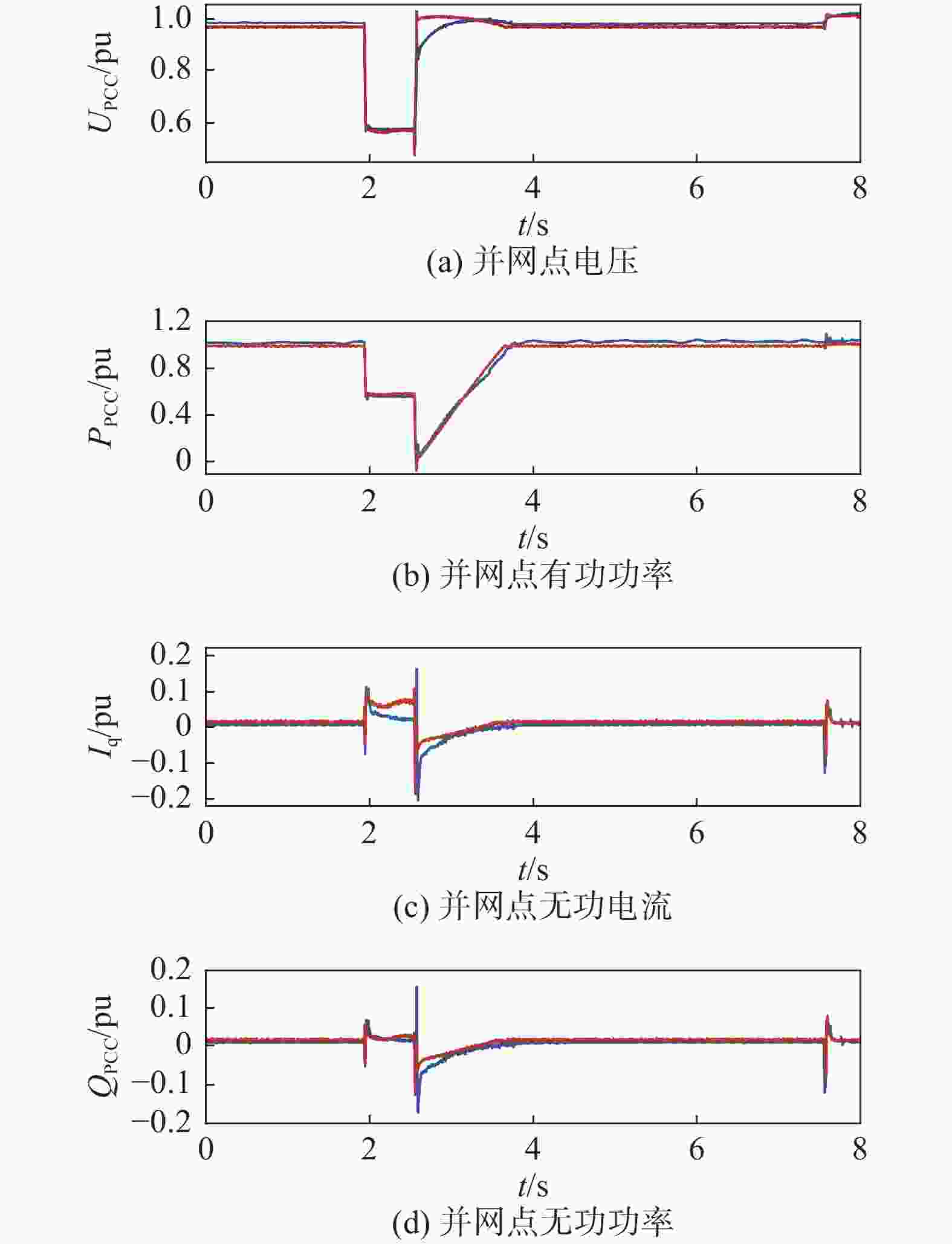
      Figure 10.  Measured and simulated waveforms of asymmetric low voltage ride through

    • 本文采用改进网侧变换器控制策略结合卸荷电路的方式可在并网点电压对称跌落/升高、不对称升高故障期间优先向电网注入无功电流,并结合卸荷电路故障期间卸放累积在直流侧电容的能量,有效提升了半直驱风电系统的故障穿越能力,通过现场测试及仿真研究得出以下结论:

      1)半直驱风电系统通过无功优先的改进网侧控制策略能在并网点对称故障及不对称升高故障工况下优先且以2倍标准要求速度向电网注入无功电流,辅助电网电压恢复,保证系统故障期间不脱网运行。

      2)在不对称低电压故障工况下,风电系统不注入无功电流,简化系统控制策略,提高系统稳定性。

      3)现场测试结果表明被测风电机组在无功电流及其响应时间、有功功率恢复速度方面均满足最新的故障电压穿越规程。

Reference (19)

Catalog

    /

    DownLoad:  Full-Size Img  PowerPoint
    Return
    Return