• Peer Review
  • Non-profit
  • Global Open Access
  • Green Channel for Rising Stars
Volume 10 Issue 4
Jul.  2023
Turn off MathJax
Article Contents

CHEN Tao, SHI Huilin, CHEN Cheng, CHEN Ke, YUAN Guokai. Research on Axial Mechanical Properties of the Grouted Connection Section Considering Installation Errors[J]. SOUTHERN ENERGY CONSTRUCTION, 2023, 10(4): 32-42. doi: 10.16516/j.gedi.issn2095-8676.2023.04.004
Citation: CHEN Tao, SHI Huilin, CHEN Cheng, CHEN Ke, YUAN Guokai. Research on Axial Mechanical Properties of the Grouted Connection Section Considering Installation Errors[J]. SOUTHERN ENERGY CONSTRUCTION, 2023, 10(4): 32-42. doi: 10.16516/j.gedi.issn2095-8676.2023.04.004

Research on Axial Mechanical Properties of the Grouted Connection Section Considering Installation Errors

doi: 10.16516/j.gedi.issn2095-8676.2023.04.004
  • Received Date: 2023-03-30
  • Rev Recd Date: 2023-06-01
  • Available Online: 2023-07-25
  • Publish Date: 2023-07-10
  •   Introduction  With the development of offshore wind turbine works to deep sea areas, the challenging construction environment tends to result in errors in the installation of the grouted connection for the jacket foundation. These errors can subsequently affect the axial mechanical properties of the grouted connection. Therefore, it is necessary to study the impact laws of installation errors on the axial mechanical properties of the grouted connection section.   Method  The study was commenced by conducting axial static loading tests on reduced-scale test piece of the grouted connection section, which was followed by simulating the axial loading process of the corresponding test piece using the finite element analysis method. The simulation results were found to align well with the experimental data, indicating a successful outcome.   Result  According to the research findings, the increasing in longitudinal and transverse installation errors can lead to an increase in the axial stiffness of the grouted connection section. This, in turn, further alters the longitudinal strain distribution of the casing and pile pipe. Additionally, the increase in installation errors can lead to an increase in the maximum value of the third principal stress in the grouting materials during the axial loading process, as well as changes in its distribution location.   Conclusion  In conclusion, the influence of installation errors on the axial mechanical properties of the grouted connection section for the jacket foundation can cause alterations in failure modes of the grouted connection section. Therefore, it is needed to consider and evaluate the harm caused by the impact laws of installation errors based on their influence rules.
  • [1] 王革栋. 海上风电基础结构选型与施工工艺探讨 [J]. 绿色环保建材, 2019(4): 235-236. DOI:  10.16767/j.cnki.10-1213/tu.2019.04.173.

    WANG G D. Discussion on offshore wind power infrastructure selection and construction technology [J]. Green environmental protection building, 2019(4): 235-236. DOI:  10.16767/j.cnki.10-1213/tu.2019.04.173.
    [2] 刘桢, 俞炅旻, 黄德财, 等. 海上风电发展研究 [J]. 船舶工程, 2020, 42(8): 20-25.

    LIU Z, YU J M, HUANG D C, et al. Offshore wind development research [J]. Ship engineering, 2020, 42(8): 20-25.
    [3] 徐荣彬, 元国凯, 刘晋超, 等. 海上风机导管架基础灌浆连接段受力分析 [J]. 南方能源建设, 2015, 2(3): 80-85. DOI:  10.16516/j.gedi.issn2095-8676.2015.03.016.

    XU R B, YUAN G K, LIU J C, et al. Analysis of grouted connection in offshore wind turbine jacket foundation [J]. Southern energy construction, 2015, 2(3): 80-85. DOI:  10.16516/j.gedi.issn2095-8676.2015.03.016.
    [4] SCHAUMANN P, LOCHTE-HOLTGREVEN S, STEPPELER S. Special fatigue aspects in support structures of offshore wind turbines [J]. Materialwissenschaft und werkstofftechnik, 2011, 42(12): 1075-1081. DOI:  10.1002/mawe.201100913.
    [5] LÖHNING T, MUURHOLM U. Finite element-based design of grouted connections with shear keys for offshore wind turbines [J]. Structural engineering international, 2013, 23(3): 295-302. DOI:  10.2749/101686613X13627347099791.
    [6] Det Norske Veritas. Design of offshore wind turbine structures: DNV-OS-J101 [S]. Norway: DNV, 2014.
    [7] 元国凯, 汤东升, 刘晋超, 等. 海上风电机组基础灌浆技术应用与发展 [J]. 南方能源建设, 2017, 4(1): 10-17. DOI:  10.16516/j.gedi.issn2095-8676.2017.01.002.

    YUAN G K, TANG D S, LIU J C, et al. Grouting technology application and development in offshore wind farm [J]. Southern energy construction, 2017, 4(1): 10-17. DOI:  10.16516/j.gedi.issn2095-8676.2017.01.002.
    [8] 徐爱民, 纪延涛, 陈志堂, 等. 浅谈钢质桩基式导管架海上安装及注意事项 [J]. 中国海洋平台, 2006, 21(6): 40-45. DOI:  10.3969/j.issn.1001-4500.2006.06.010.

    XU A M, JI Y T, CHEN Z T, et al. Disassembly installation and attention problems of petrol pipe-platform on the sea [J]. China offshore platform, 2006, 21(6): 40-45. DOI:  10.3969/j.issn.1001-4500.2006.06.010.
    [9] DNVGL. Analysis of grouted connections using the finite element method: DNVGL-RP-0419 [S]. Norway: DNV, 2016.
    [10] LAMPORT W B, JIRSA J O, YURA J A. Strength and behavior of grouted pile-to-sleeve connections [J]. Journal of structural engineering, 1991, 117(8): 2477-2498. DOI:  10.1061/(ASCE)0733-9445(1991)117:8(2477).
    [11] 吴兆旗, 游先辉, 单宁康, 等. 考虑偏心的不同尺寸灌浆连接轴向承载性能 [J]. 广西大学学报(自然科学版), 2021, 46(4): 854-865. DOI:  10.13624/j.cnki.issn.1001-7445.2021.0854.

    WU Z Q, YOU X H, SHAN N K, et al. Axial load capacity of grouted connections with different sizes considering eccentricity [J]. Journal of Guangxi University (natural science edition), 2021, 46(4): 854-865. DOI:  10.13624/j.cnki.issn.1001-7445.2021.0854.
    [12] 李筑轩, 陈涛, 赵淇, 等. 考虑偏心误差的灌浆连接段受弯承载力研究 [J]. 建筑结构学报, 2017, 38(增刊1): 465-470. DOI:  10.14006/j.jzjgxb.2017.S1.065.

    LI Z X, CHEN T, ZHAO Q, et al. Bending behavior of grouted connections considering eccentricity errors [J]. Journal of building structures, 2017, 38(Suppl. 1): 465-470. DOI:  10.14006/j.jzjgxb.2017.S1.065.
    [13] 宗红霞. 海上风机单桩基础扶正导向装置研究 [D]. 哈尔滨: 哈尔滨工程大学, 2009. DOI:  10.7666/d.y1489301.

    ZONG H X. Research on declination rectification and guidance device based on offshore wind turbine mnopile foundation [D]. Harbin: Harbin Engineering University, 2009. DOI:  10.7666/d.y1489301.
    [14] 兰世平, 周通, 贾小刚. 深远海海上风电导管架基础安装技术与实践探索 [J]. 水电与新能源, 2020, 34(2): 39-42. DOI:  10.13622/j.cnki.cn42-1800/tv.1671-3354.2020.02.009.

    LAN S P, ZHOU T, JIA X G. Exploration and practice of the jacket foundation installation technology for far-reaching offshore wind power projects [J]. Hydropower and new energy, 2020, 34(2): 39-42. DOI:  10.13622/j.cnki.cn42-1800/tv.1671-3354.2020.02.009.
    [15] 武晓飞. 开放海域淤泥质地基水下导管架基础施工精度控制技术研究 [J]. 工程技术研究, 2020, 5(12): 108-109. DOI:  10.19537/j.cnki.2096-2789.2020.12.051.

    WU X F. Research on construction accuracy control technology of underwater jacket foundation in silt texture in open sea [J]. Engineering and technological research, 2020, 5(12): 108-109. DOI:  10.19537/j.cnki.2096-2789.2020.12.051.
    [16] BETONBAU. Design [M]//FIB. Fib Model Code for Concrete Structures 2010. Lausanne: Ernst & Sohn, 2013: 190-350. DOI: 10.1002/9783433604090.ch7.
    [17] 聂建国, 王宇航. ABAQUS中混凝土本构模型用于模拟结构静力行为的比较研究 [J]. 工程力学, 2013, 30(4): 59-67. DOI:  10.6052/j.issn.1000-4750.2011.07.0420.

    NIE J G, WANG Y H. Comparison study of constitutive model of concrete in ABAQUS for static analysis of structures [J]. Engineering mechanics, 2013, 30(4): 59-67. DOI:  10.6052/j.issn.1000-4750.2011.07.0420.
    [18] 陈涛, 姚政韬, 王衔, 等. 海上风机灌浆连接段应力评价方法探析 [J]. 南方能源建设, 2020, 7(1): 33-39. DOI:  10.16516/j.gedi.issn2095-8676.2020.01.005.

    CHEN T, YAO Z T, WANG X, et al. A stress evaluation method for grouted connections of offshore wind turbines [J]. Southern energy construction, 2020, 7(1): 33-39. DOI:  10.16516/j.gedi.issn2095-8676.2020.01.005.
    [19] 仲伟秋, 麻晔, 杨礼东, 等. 海上风电桩基础与导管架灌浆连接段的ANSYS分析 [J]. 沈阳建筑大学学报(自然科学版), 2012, 28(4): 663-669.

    ZHONG W Q, MA Y, YANG L D, et al. The analysis of grouted connection between pile foundation and jacket for offshore wind turbine by ANSYS [J]. Journal of Shenyang Jianzhu University (natural science edition), 2012, 28(4): 663-669.
    [20] 陈涛, 房奇, 张持海, 等. 压弯荷载下单桩基础灌浆连接段性能分析 [J]. 南方能源建设, 2020, 7(4): 26-33. DOI:  10.16516/j.gedi.issn2095-8676.2020.04.004.

    CHEN T, FANG Q, ZHANG C H, et al. Mechanical properties of the grouted connection under the action of compression-bending load [J]. Southern energy construction, 2020, 7(4): 26-33. DOI:  10.16516/j.gedi.issn2095-8676.2020.04.004.
    [21] LOTSBERG I. Structural mechanics for design of grouted connections in monopile wind turbine structures [J]. Marine structures, 2013, 32: 113-135. DOI:  10.1016/j.marstruc.2013.03.001.
  • 通讯作者: 陈斌, bchen63@163.com
    • 1. 

      沈阳化工大学材料科学与工程学院 沈阳 110142

    1. 本站搜索
    2. 百度学术搜索
    3. 万方数据库搜索
    4. CNKI搜索

Figures(16)  / Tables(1)

Article Metrics

Article views(97) PDF downloads(29) Cited by()

Related

Research on Axial Mechanical Properties of the Grouted Connection Section Considering Installation Errors

doi: 10.16516/j.gedi.issn2095-8676.2023.04.004

Abstract:   Introduction  With the development of offshore wind turbine works to deep sea areas, the challenging construction environment tends to result in errors in the installation of the grouted connection for the jacket foundation. These errors can subsequently affect the axial mechanical properties of the grouted connection. Therefore, it is necessary to study the impact laws of installation errors on the axial mechanical properties of the grouted connection section.   Method  The study was commenced by conducting axial static loading tests on reduced-scale test piece of the grouted connection section, which was followed by simulating the axial loading process of the corresponding test piece using the finite element analysis method. The simulation results were found to align well with the experimental data, indicating a successful outcome.   Result  According to the research findings, the increasing in longitudinal and transverse installation errors can lead to an increase in the axial stiffness of the grouted connection section. This, in turn, further alters the longitudinal strain distribution of the casing and pile pipe. Additionally, the increase in installation errors can lead to an increase in the maximum value of the third principal stress in the grouting materials during the axial loading process, as well as changes in its distribution location.   Conclusion  In conclusion, the influence of installation errors on the axial mechanical properties of the grouted connection section for the jacket foundation can cause alterations in failure modes of the grouted connection section. Therefore, it is needed to consider and evaluate the harm caused by the impact laws of installation errors based on their influence rules.

CHEN Tao, SHI Huilin, CHEN Cheng, CHEN Ke, YUAN Guokai. Research on Axial Mechanical Properties of the Grouted Connection Section Considering Installation Errors[J]. SOUTHERN ENERGY CONSTRUCTION, 2023, 10(4): 32-42. doi: 10.16516/j.gedi.issn2095-8676.2023.04.004
Citation: CHEN Tao, SHI Huilin, CHEN Cheng, CHEN Ke, YUAN Guokai. Research on Axial Mechanical Properties of the Grouted Connection Section Considering Installation Errors[J]. SOUTHERN ENERGY CONSTRUCTION, 2023, 10(4): 32-42. doi: 10.16516/j.gedi.issn2095-8676.2023.04.004
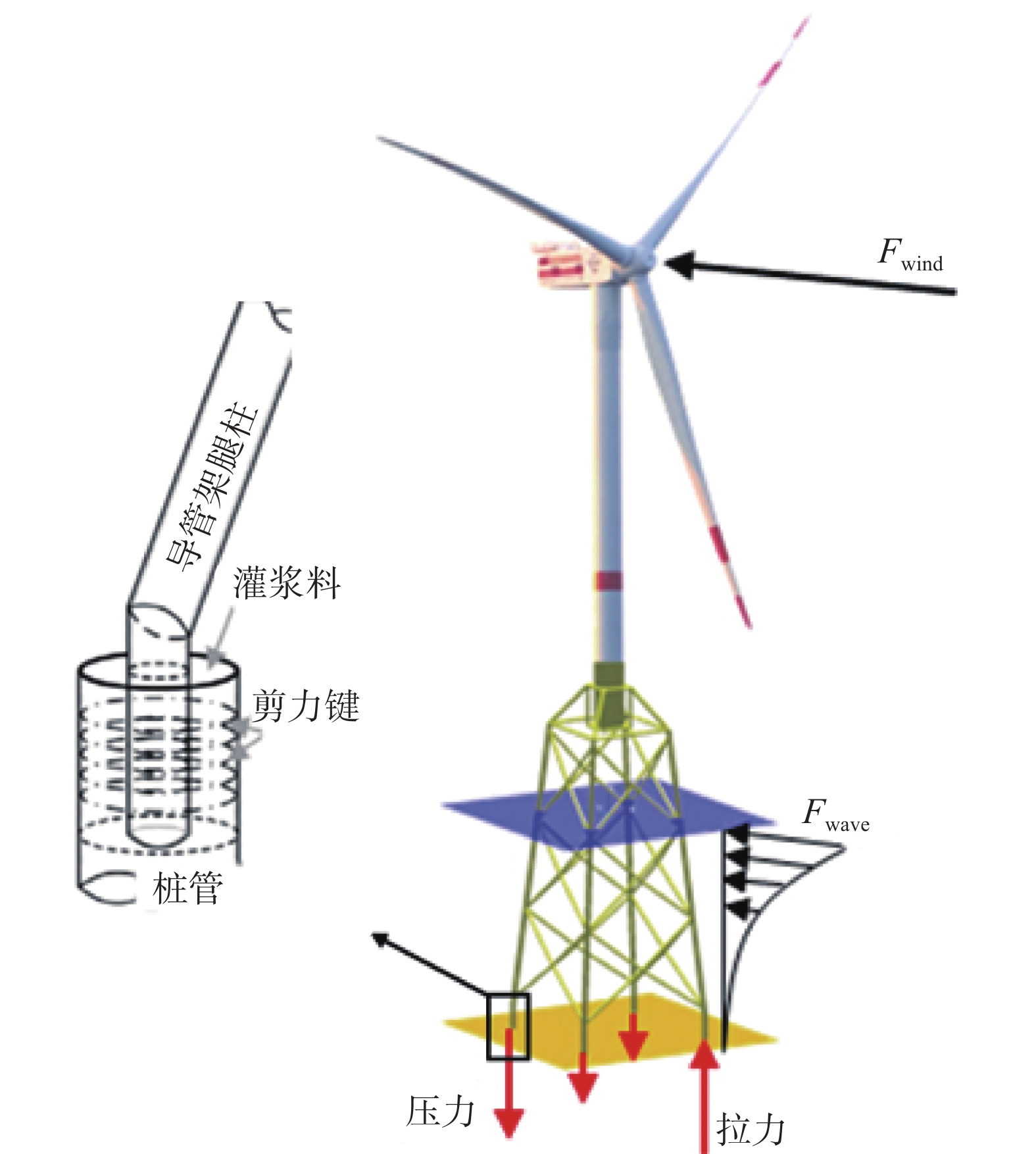
    • 随着海上风机工程向着环境更加复杂的深远海地区发展,导管架基础被越来越多地应用于深海水域(水深≥30 m)的项目建设之中[1-2]。根据施工方法的不同,导管架基础中的导管架套管与桩管的安装方式可以分为后桩法和先桩法两类[3]。而两种方法中桩管都通过灌浆连接段与套管相连接,灌浆连接段则在受力过程中主要承受轴力作用[4-5]。这是由于在实际工程中,海上风机的自重荷载以及所受的风浪荷载会直接作用于导管架,导管架则通过各支撑桁架内的轴力来平衡外力,并将轴力传递到灌浆连接段,灌浆连接段又通过套管与桩管管壁上相邻剪力键之间的灌浆料来将轴力进一步传递给外部桩管,最终由桩管将轴力传递到海床地基[6],其受力过程如图1所示。

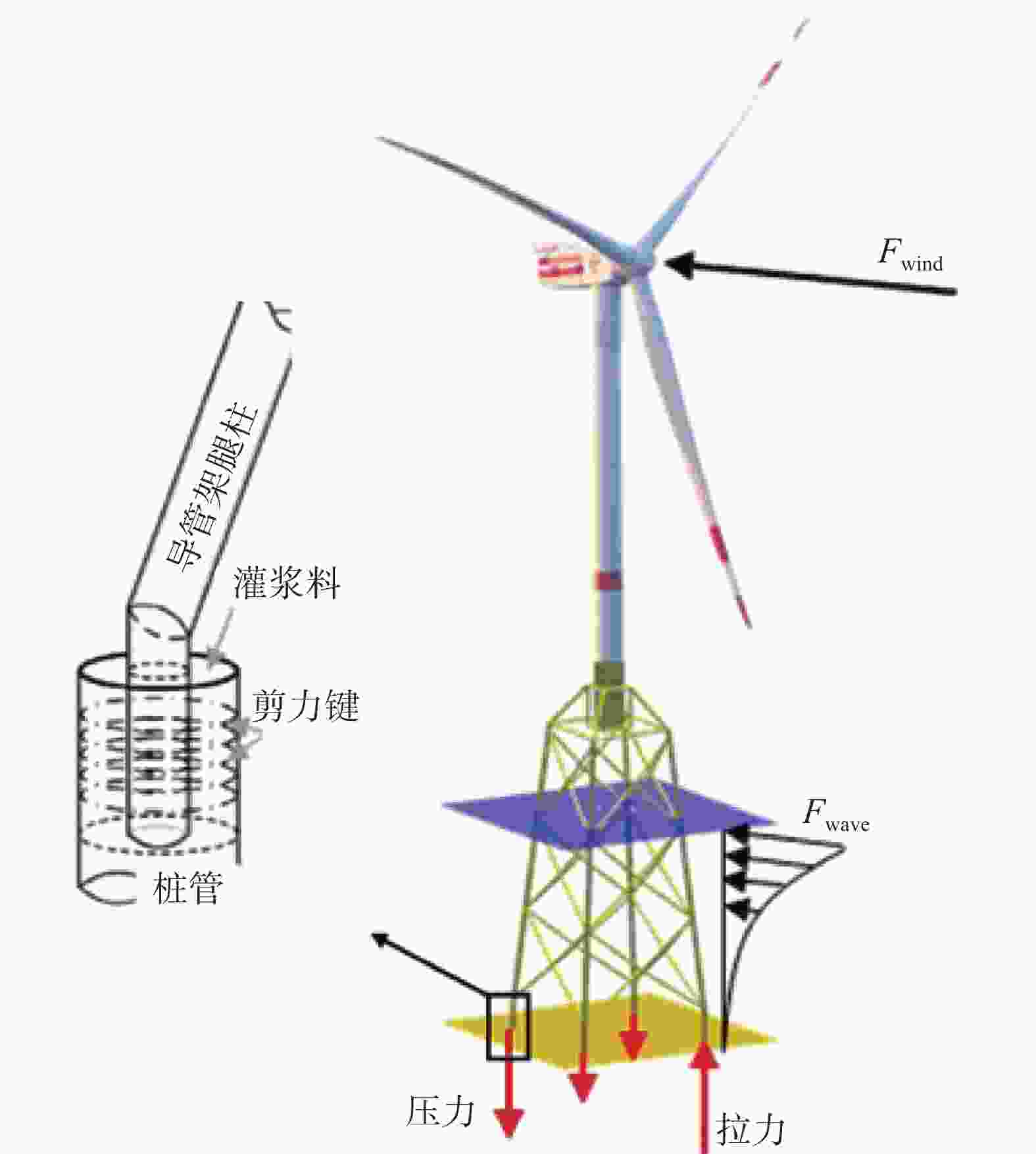
      Figure 1.  Structure and stressing process of jacket foundation

      导管架基础的灌浆连接段是传力的关键路径,其安装位置位于海床处[7]。然而由于海上施工环境十分恶劣,导管架的定位和安装常受到大风、海浪以及海底地质的干扰[8],这使得套管与桩管在对接时极易产生安装误差。根据DNV规范[9]的分类,安装误差可被具体分为纵向安装误差v、横向安装误差e和倾斜安装误差i这3类。其中,Lamport等[10]曾研究过横向安装误差对灌浆连接段轴向极限承载力的影响,其研究结果表明灌浆连接段的轴向极限承载力随着横向安装误差的增加而发生明显下降;吴兆旗等[11]则是围绕横向安装误差开展了灌浆连接段的缩尺试验以及有限元模拟,其研究结果表明横向安装误差会导致厚度不均的灌浆层在加载过程中呈现不同的应变变化;李筑轩等[12]则是对考虑横向安装误差的灌浆连接段的受弯承载力进行了研究。另外,目前国内施工在考虑灌浆连接段的安装误差时常用导向块进行辅助定位,其精度主要取决于导向块的布置以及灌浆连接段的几何尺寸[13]。然而从整体来看,目前有关安装误差对灌浆连接段轴向力学性能影响的研究以及设计施工方法仍然存在较大空白[14-15],因此,需要围绕安装误差对海上风机导管架基础灌浆连接段轴向力学性能的影响开展更进一步的研究。

      综上所述,文章以含有安装误差的海上风机导管架基础灌浆连接段的缩尺试件为研究对象,一方面开展轴向静力加载试验,另一方面建立相关的有限元数值模型来进一步验证试验结果的准确性,最后基于试验和有限元分析结果,对纵向、横向以及倾斜安装误差有关海上风机导管架基础灌浆连接段轴向力学性能的影响规律进行分析与讨论。

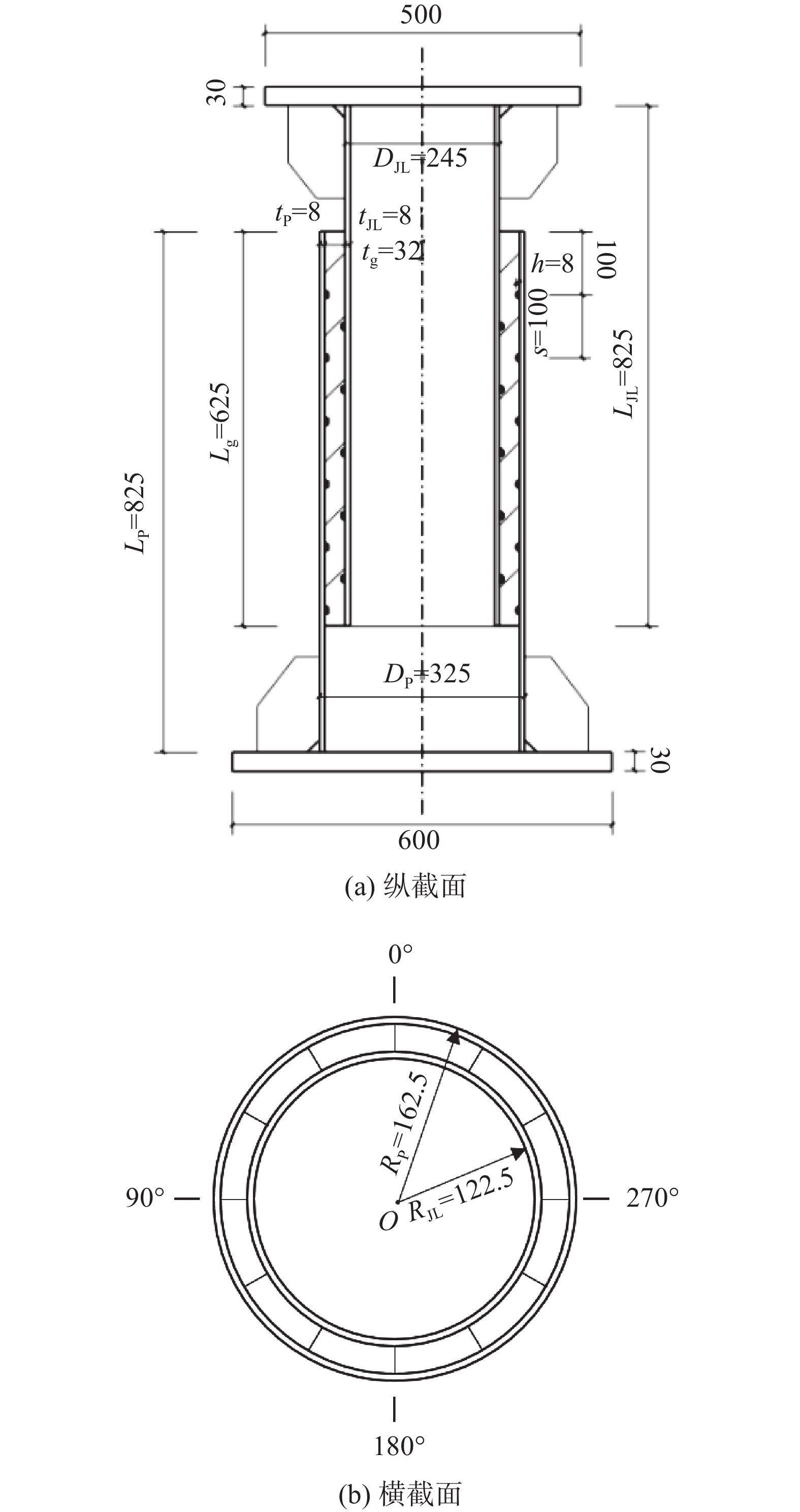
    • 文章采用导管架基础灌浆连接段的缩尺试件开展轴向静力加载试验,其中无安装误差的标准试件编号为A-1,具体尺寸如图2所示。灌浆连接段试件的套管外壁直径为245 mm,桩管外壁直径为325 mm,两者管壁厚均为8 mm,中间连接段灌浆段长度为625 mm,并含有5对剪力键,剪力键间距为100 mm。

      Figure 2.  Schematic diagram of reduced-scale test piece A-1

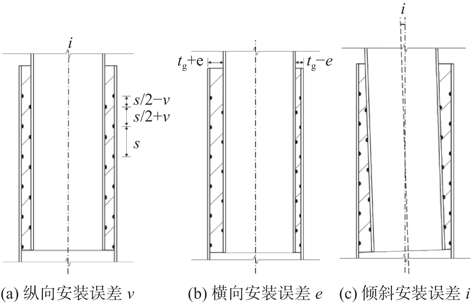
      基于DNV规范[9]的分类标准中关于安装误差的分类,文章对灌浆连接段安装误差的定义方式如图3所示。

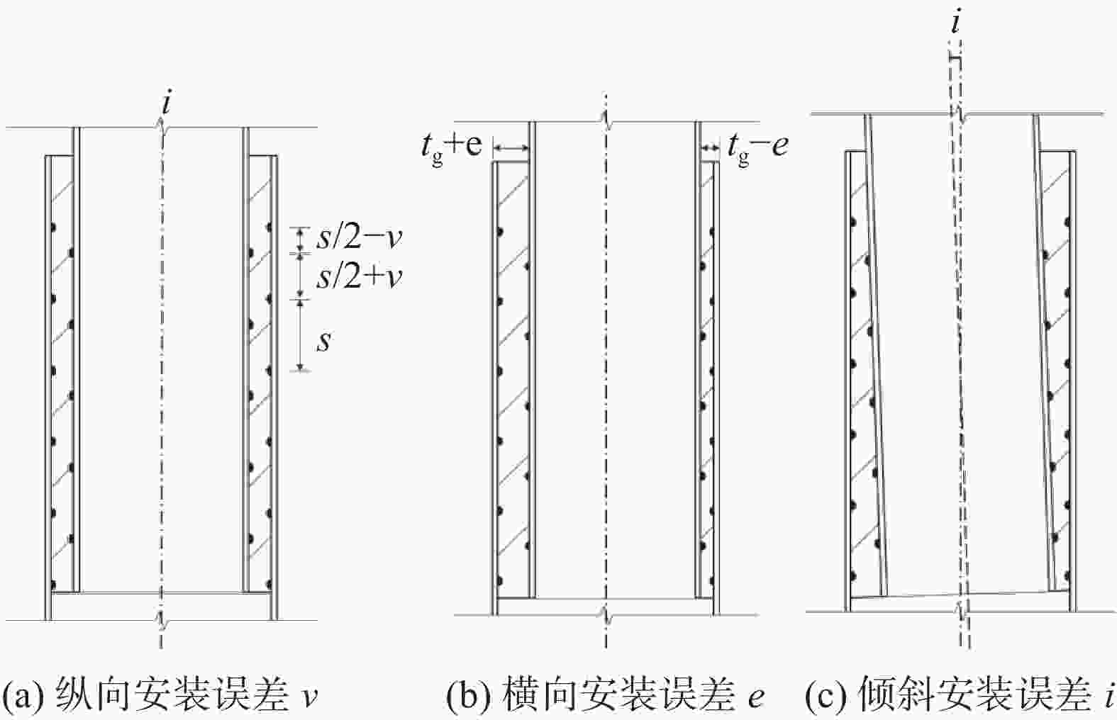
      Figure 3.  Definition and schematic diagram of installation error parameters

      为了研究纵向和横向安装误差对于灌浆连接段的轴向力学性能的影响,文章基于标准试件A-1分别设计了误差试件D1A-2和D3A-2,其试件的几何参数以及所含误差如表1所示。

      试件编号套管桩管灌浆段剪力键安装误差
      外径DJL/mm厚度tJL/mm长度LJL/mm外径Dp/mm厚度tp/mm长度Lp/mm长度Lg/mm厚度tg/mm间距s/mm高度h/mm数量n
      A-1245882532588256253210065
      D1A-2245882532588256253210065v/s=0.25
      D3A-2245882532588256253210065e/tg=0.375

      Table 1.  Specific parameters and grouping of reduced-scale test pieces

    • 对本试验中所用钢材开展材性试验,可得钢材的弹性模量为2.09×10⁵ MPa,屈服强度为301.7 MPa,极限抗拉强度为474.5 MPa;对所用灌浆料进行材性试验,可得灌浆料的弹性模量为4.36×10⁴ MPa,圆柱体抗压强度为78.3 MPa,同时根据欧洲混凝土规范CEB-FIP-2010[16],可进一步计算得到灌浆料的断裂能为0.175 3 N/mm。

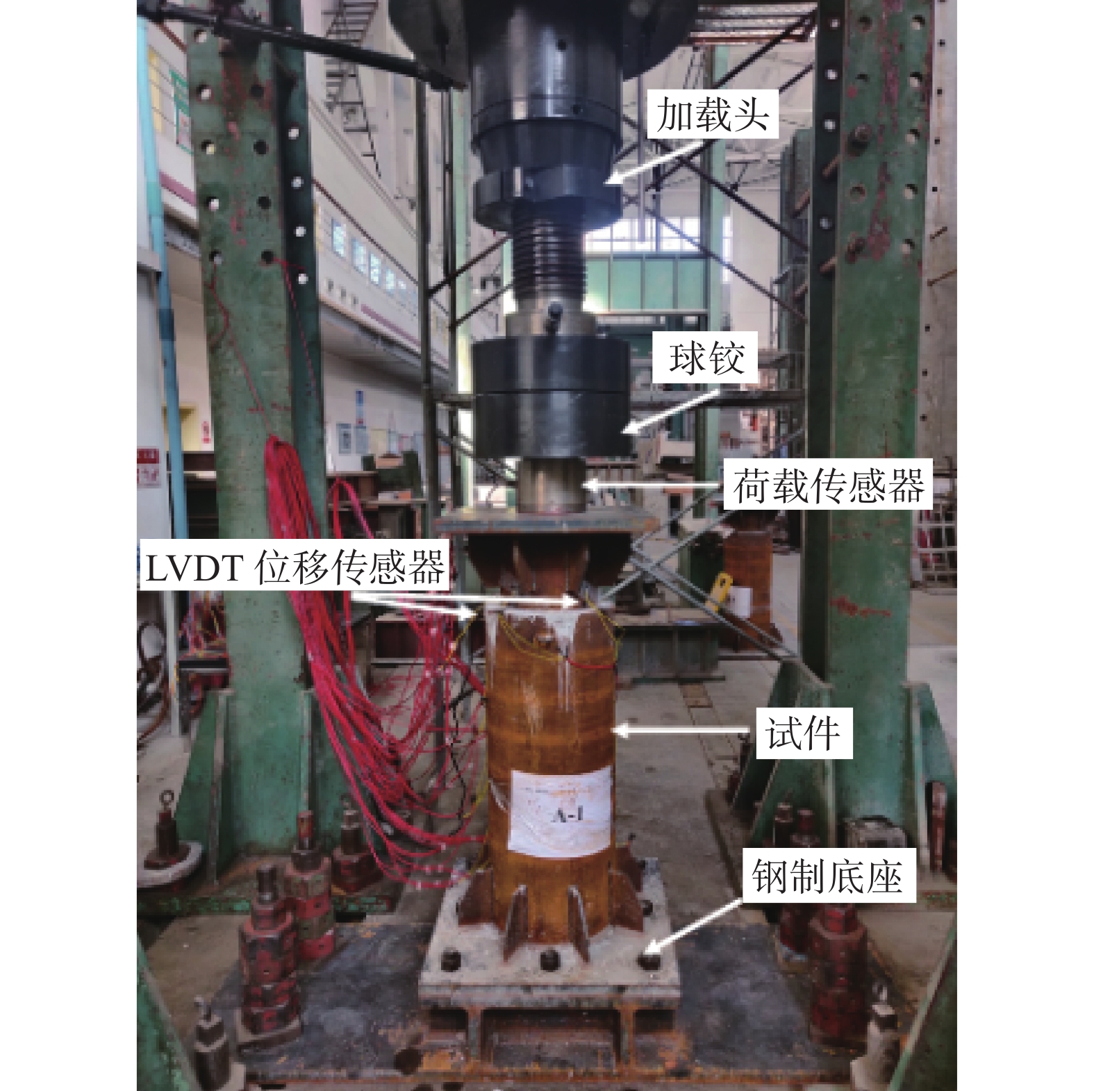
    • 该轴向静力加载试验在上海市建筑科学研究院结构试验室开展,加载装置包括加载头、球铰、荷载传感器以及钢制底座等,如图4所示,位移计分布以及测量内容如图5所示。试验中所采用的最大轴向荷载Pmax=696.75 kN,且加载过程采用分级加载,即将最大荷载平均分为5级依次加载,且每次需等待上一级荷载稳定后,再开始下一级荷载的加载。

      Figure 4.  Axial static loading devices

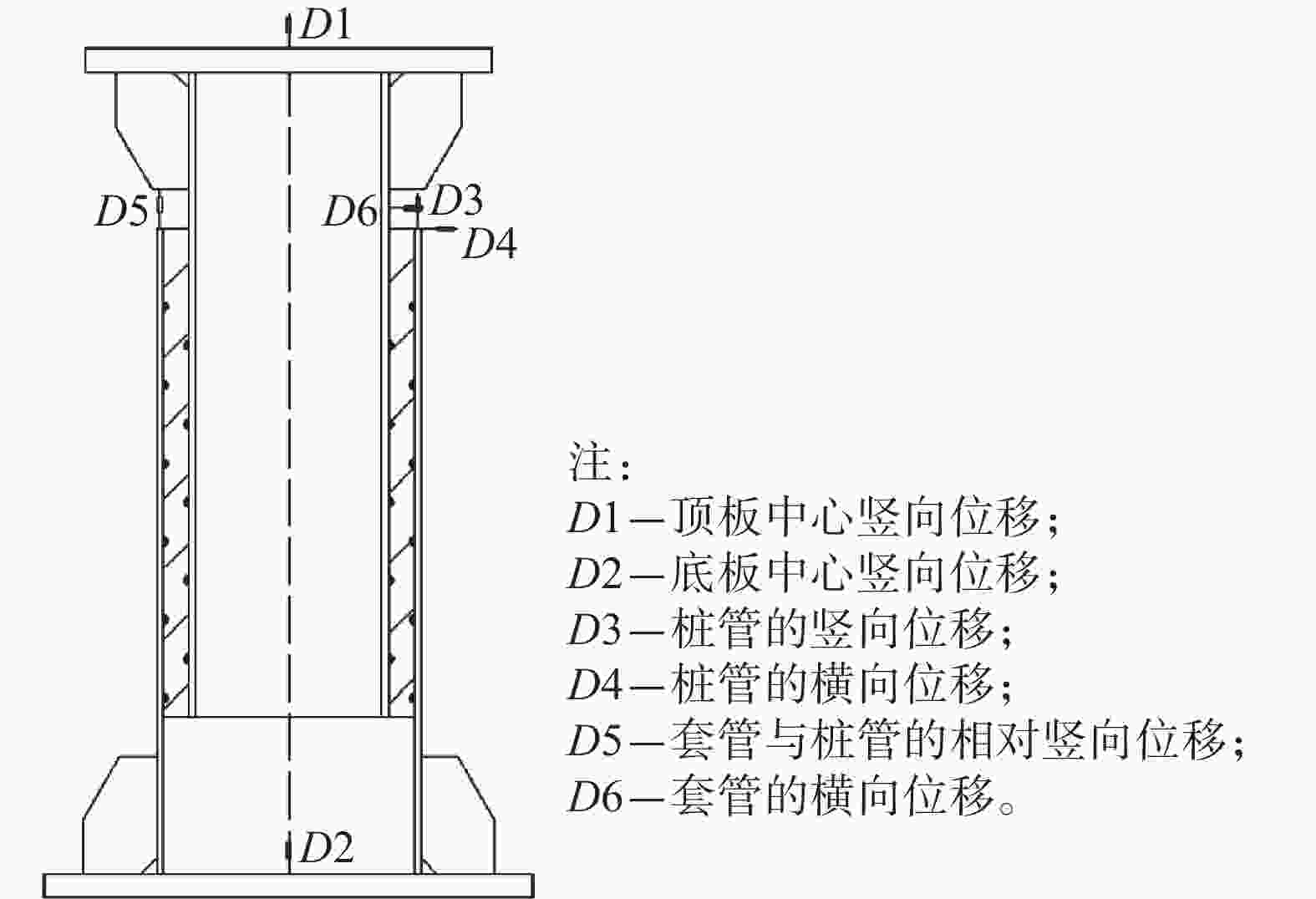
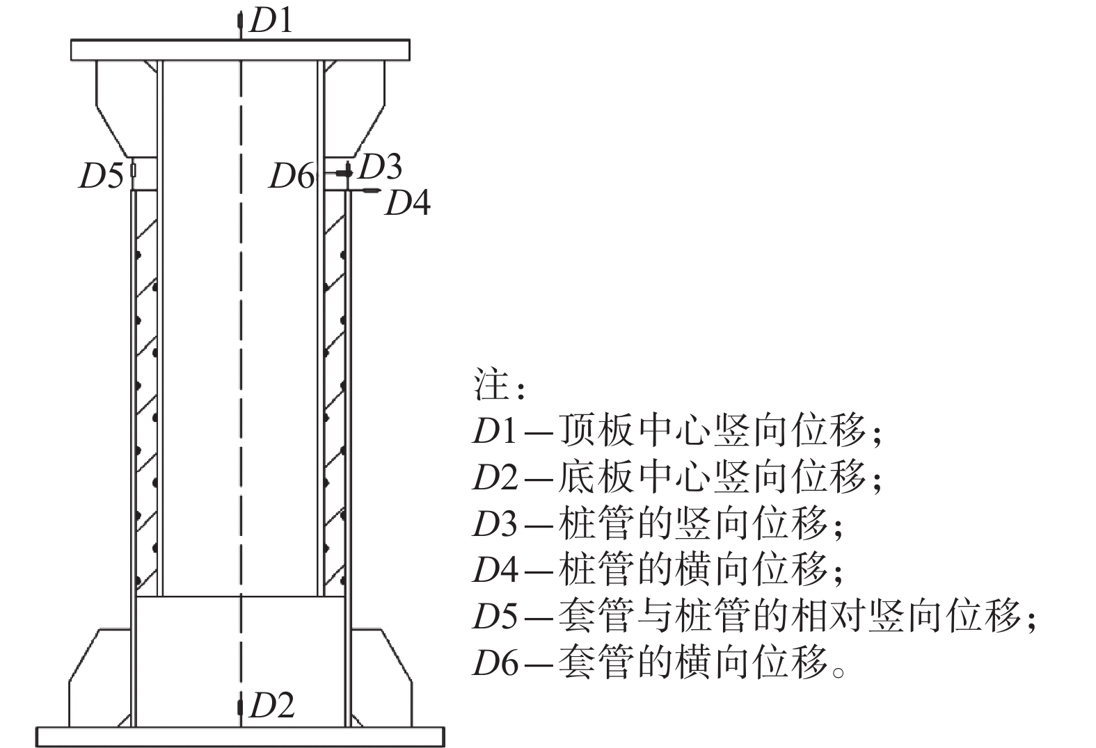
      Figure 5.  Displacement meter distribution and measured items

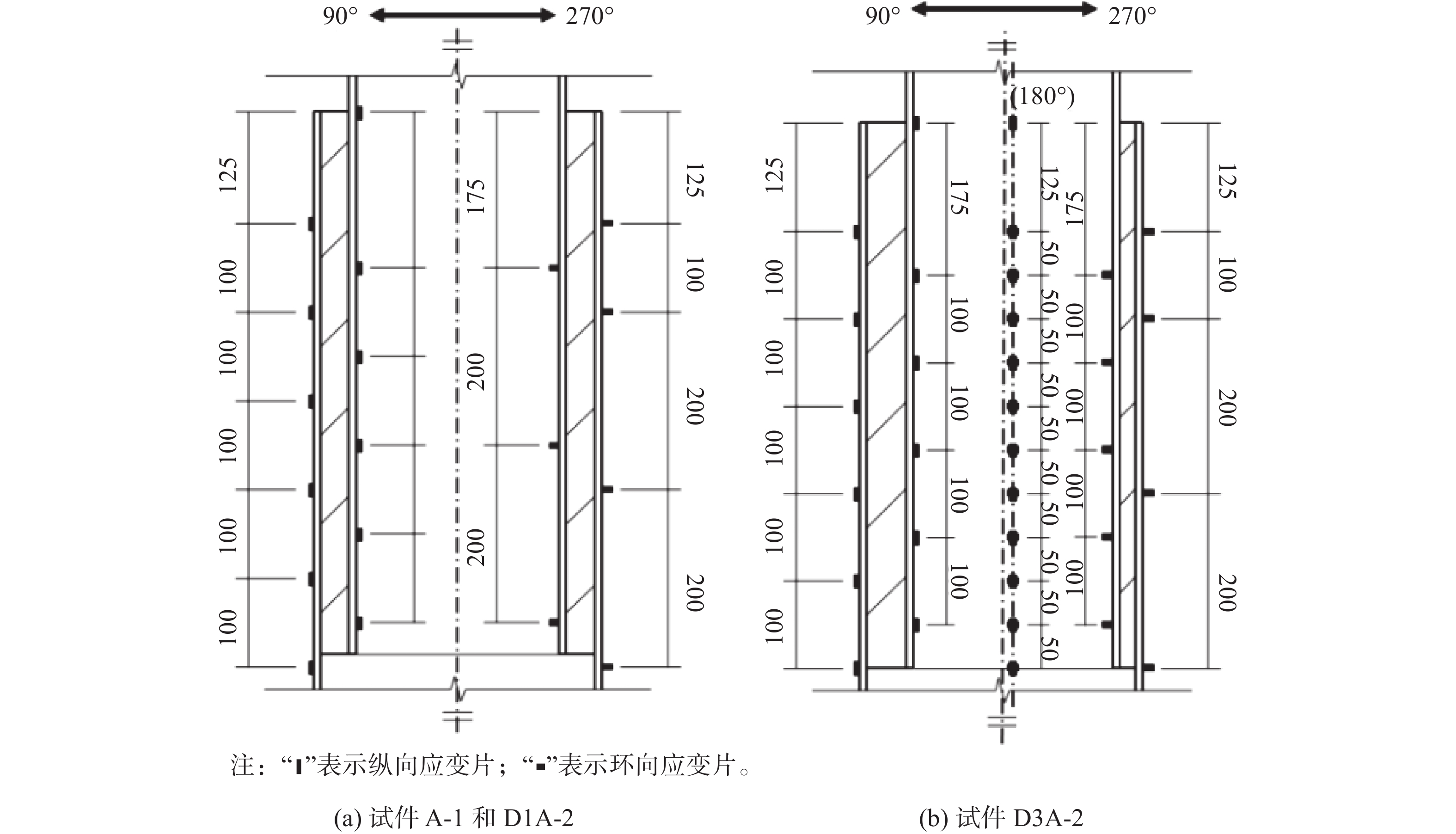
    • 本试验中采用应变片对灌浆连接段试件的各点应变变化进行测量。其中,对于纵向安装误差试件D1A-2,其应变片对称布置在试件90°~270°的纵截面平面上,共38个应变片,如图6(a)所示;对于横向安装误差试件D3A-2,考虑到管内的灌浆料厚度分布并不均匀,其应变片除在横向安装误差所在截面布置应变片(270°方向为灌浆料最厚侧,90°方向为灌浆料最薄侧),还需在套管180°方向一侧布置,共计65个,如图6(b)所示。

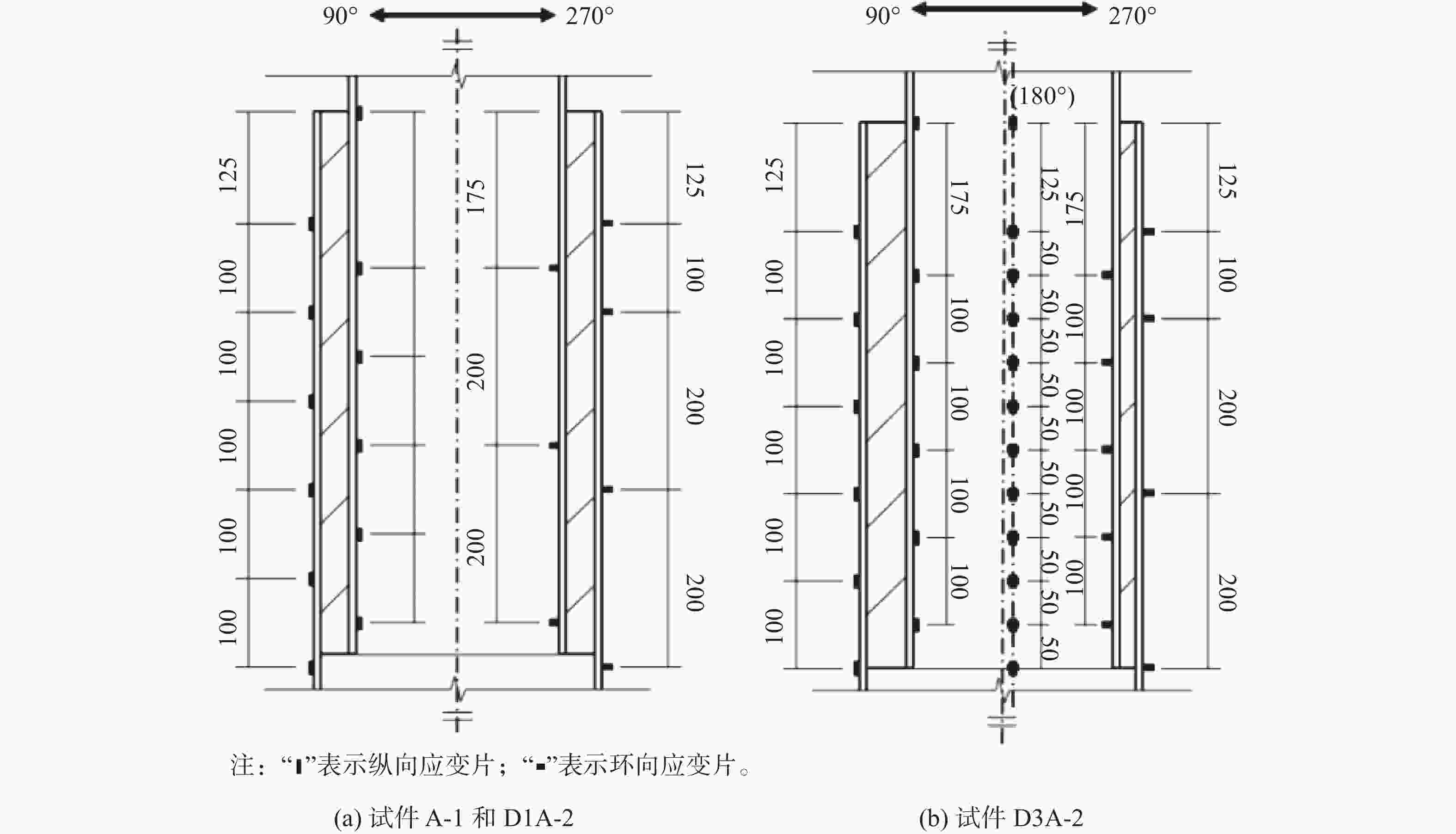
      Figure 6.  Schematic diagram of strain gage distribution

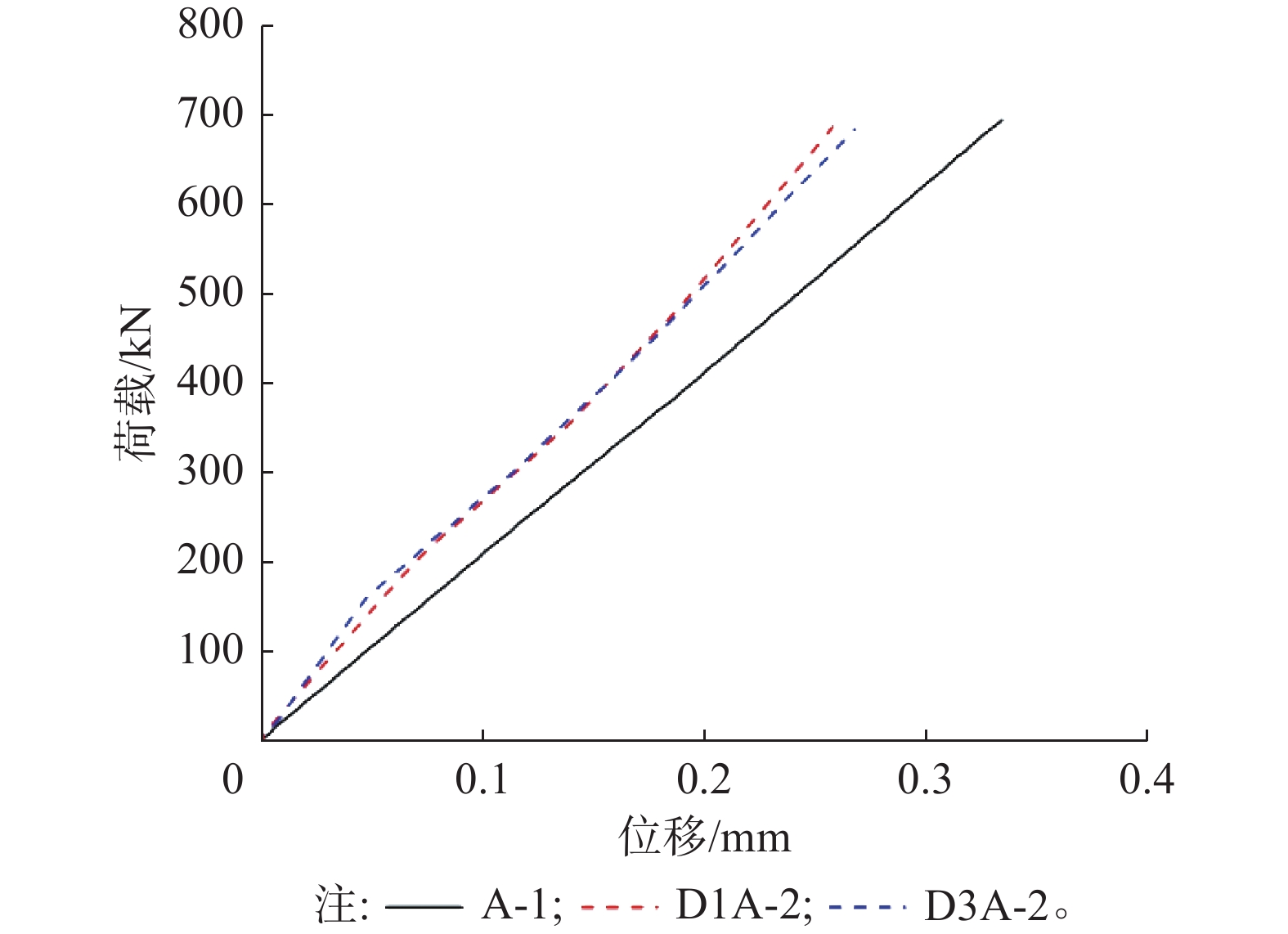
    • 以灌浆连接段试件顶板与底板的位移差值作为套管与钢管的相对位移量,并将试件D1A-2、D3A-2的轴向荷载-相对位移曲线与试件A-1进行对比,如图7所示,3个试件在轴向静力加载过程中始终处于弹性阶段,荷载与位移呈线性比例增大。然而,含有纵向安装误差(v/s=0.25)的试件D1A-2较标准试件A-1的轴向刚度有所增大,即在最大试验荷载Pmax=696.75 kN下,试件D1A-2的位移为0.263 mm,试件A-1的位移为0.336 mm,v/s=0.25的纵向安装误差下灌浆连接段的轴向刚度增大约28%;而含有横向安装误差(e/tg=0.375)的试件D3A-2较标准试件A-1的轴向刚度也有所增大,即在最大试验荷载Pmax=696.75 kN下,试件D3A-2的位移为0.273 mm,试件A-1的位移为0.336 mm,e/tg=0.375的横向安装误差下灌浆连接段的轴向刚度增大约23%。

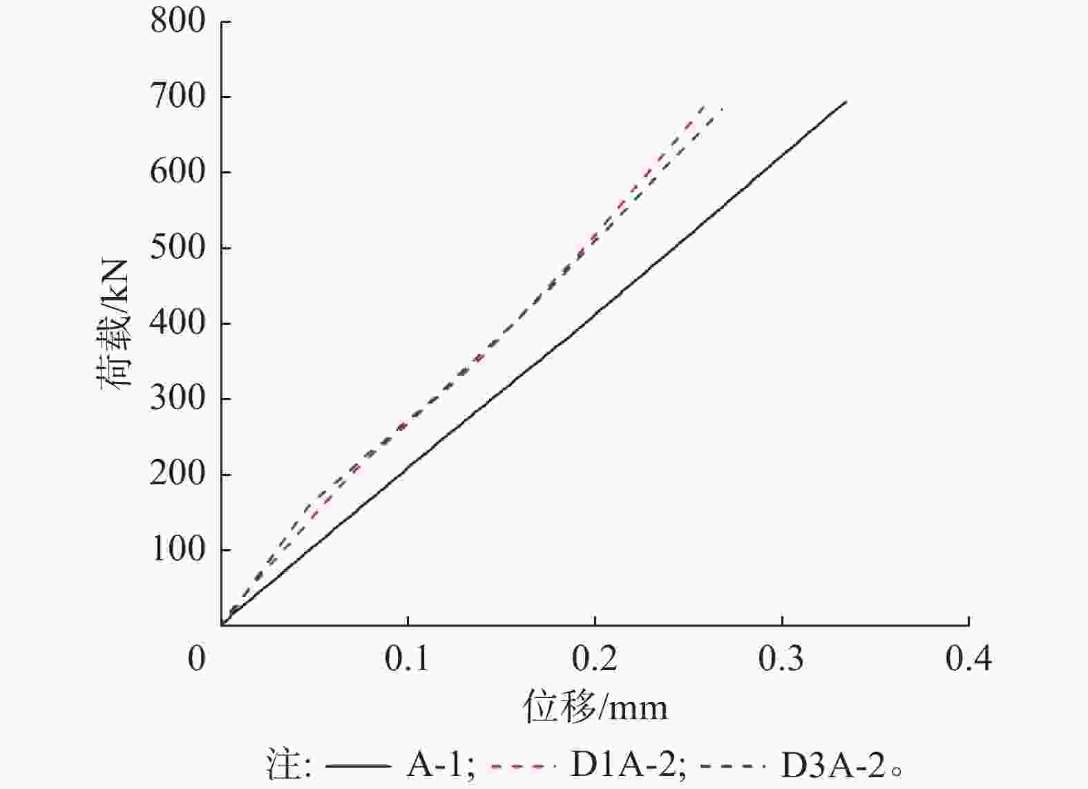
      Figure 7.  Comparison of load-displacement curves between error test pieces and standard test pieces

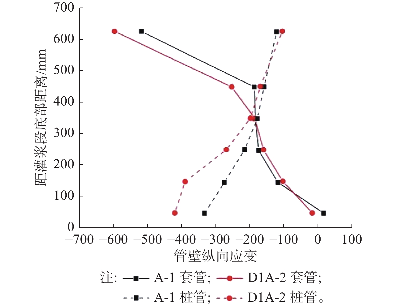
      另外,文章也从套管和桩管管壁纵向应变的角度对误差试件的结果进行比较分析:对于含有纵向安装误差的试件D1A-2,其与标准试件A-1相比,两者的应变分布趋势相近,即套管管壁上部应变大下部应变小,桩管管壁上部应变小下部应变大,如图8所示。然而在纵向安装误差影响下,套管管壁最上部应变和桩管管壁最下部应变分别增大了15%和26%,这说明纵向安装误差对灌浆连接段端部的纵向应变大小有一定的放大作用。

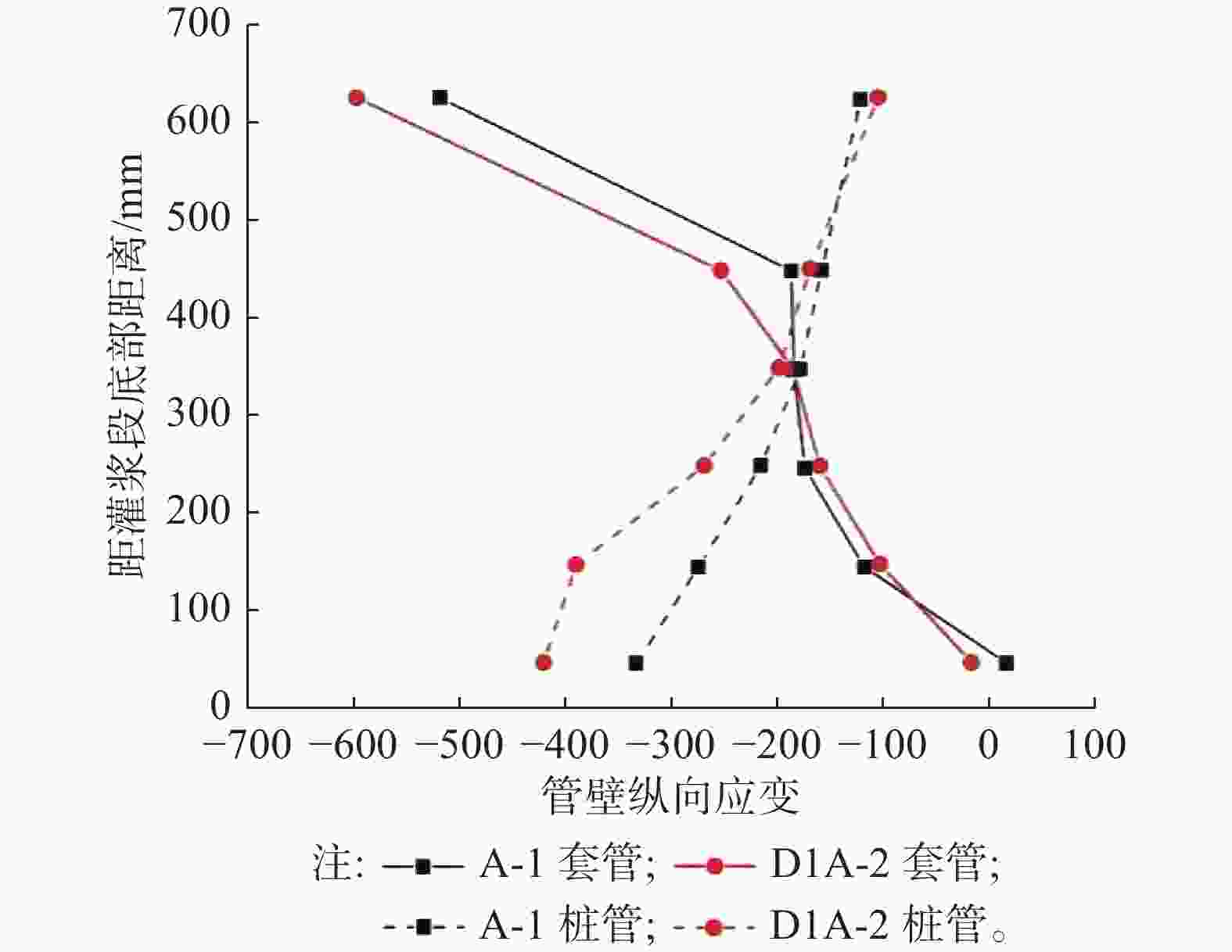
      Figure 8.  Comparison of longitudinal strain distribution on pipe wall between test piece D1a-2 and test piece A-1

      对于含有横向安装误差的试件D3A-2,其套管和桩管管壁各个方向的纵向应变分布趋势也并没有随着横向安装误差的出现而发生改变,其总体应变分布趋势依然是套管上部应变大下部应变小,桩管上部应变小下部应变大,如图9所示,这符合了灌浆连接段的传力机制。但由于横向安装误差的影响,套管管壁最上部的应变在90°方向一侧增大了22%,180°方向一侧减小了37%,270°方向一侧减小了4%;桩管管壁最下部的应变在90°方向一侧增大了7%,180°一侧减小了12%,270°一侧增大了9%,这说明横向安装误差较明显地改变了灌浆连接段的应变分布,从而可能改变灌浆连接段在轴向加载下的破坏模式。

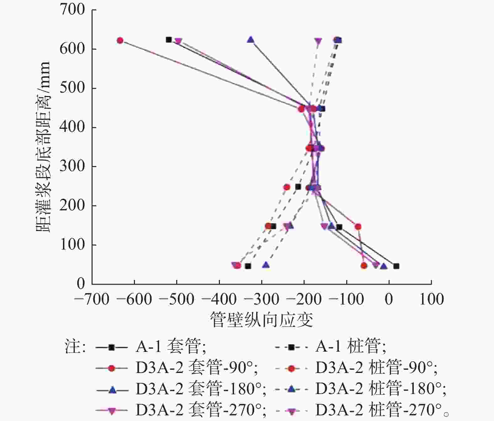
      Figure 9.  Comparison of longitudinal strain on pipe wall between test piece D3a-2 and test piece A-1

    • 为了验证缩尺试验结果的准确性,也为了进一步研究安装误差参数对灌浆连接段轴向力学性能的影响,文章采用有限元软件ABAQUS建立了与缩尺试件相对应的有限元数值模型,并对其结果进行了分析和讨论。

      基于材性试验的数据,对有限元数值模型中的钢材和灌浆料的强度和弹性模量等参数进行定义。其中,灌浆材料的损伤破坏行为采用混凝土塑性损伤模型(CDP模型)[17],该模型中所采用的参数为:膨胀角为30°,偏心距为0.1,投影形状参数K为0.67,强度比值fb0/fc为1.16,粘性系数为0.001。

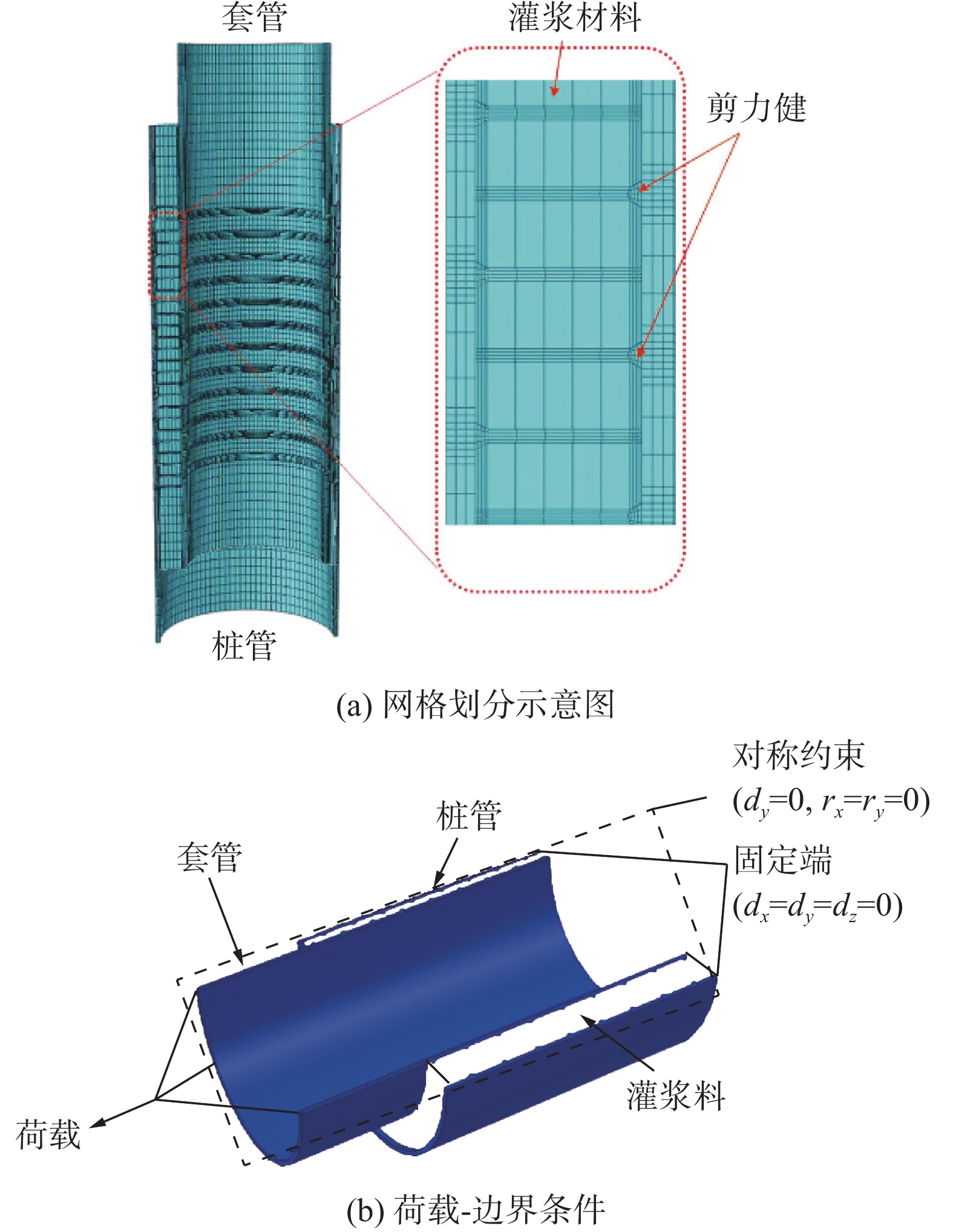
    • 有限元模型的几何尺寸与缩尺试验中对应的试件尺寸相同,其中桩管、套管和灌浆料均采用C3D8R单元进行计算。根据数值分析方法的相关研究[18-19],文章也对模型进行了网格敏感性分析。结果表明模型剪力键周围的应力分布对网格尺寸非常敏感,为防止网格畸变和提高局部应力计算结果的准确度,需适当减小分析步,并对剪力键及其相邻区域进行精细化网格划分,具体如图10(a)所示。

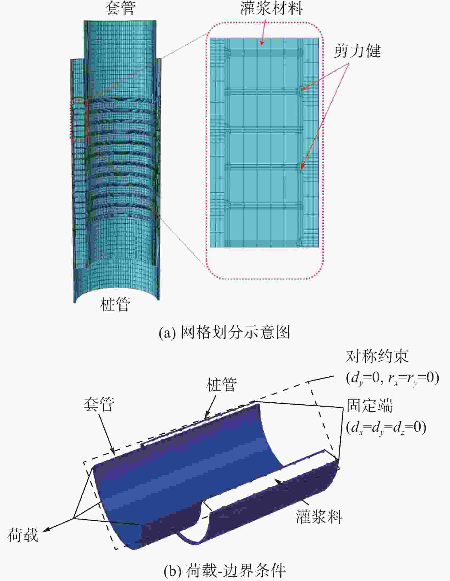
      Figure 10.  Finite element modeling method for grouted connection section

      另外,考虑到各试件均为以90°~270°所在平面为中心的镜面对称结构,故采用对称面约束的半模型以及套管、桩管和灌浆层独立建模后再装配的建模方法[20]。其中,钢管与灌浆料的法线方向定义为硬接触,切线方向定义为无黏结的库伦摩擦模型,摩擦系数为0.412[21]。有限元模型的约束条件为桩管下表面结点完全固定,荷载通过设置耦合点作用于套管上表面,其具体边界条件及荷载的定义可如图10(b)所示。

    • 基于有限元计算结果,将灌浆连接段数值模型的轴向荷载-相对位移曲线与实际缩尺试件数据进行比较,同时比较两者在应变分布结果上的区别。

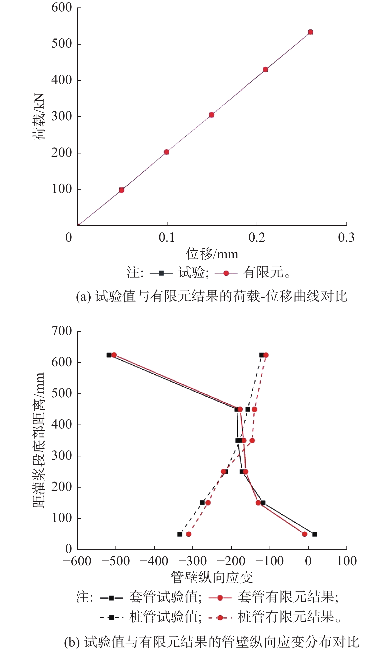
      对于标准试件A-1,其试验值与数值模拟结果的荷载-位移曲线的对比如图11(a)所示,其在最大试验荷载Pmax=696.75 kN下,试验所测位移值为0.336 mm,有限元模拟的位移值为0.335 mm,相对误差不超过0.3%;而其内外钢管管壁的纵向应变(试件90°方向一侧应变)对比结果则如图11(b)所示,其有限元计算结果与实际试验数据的拟合效果较好。

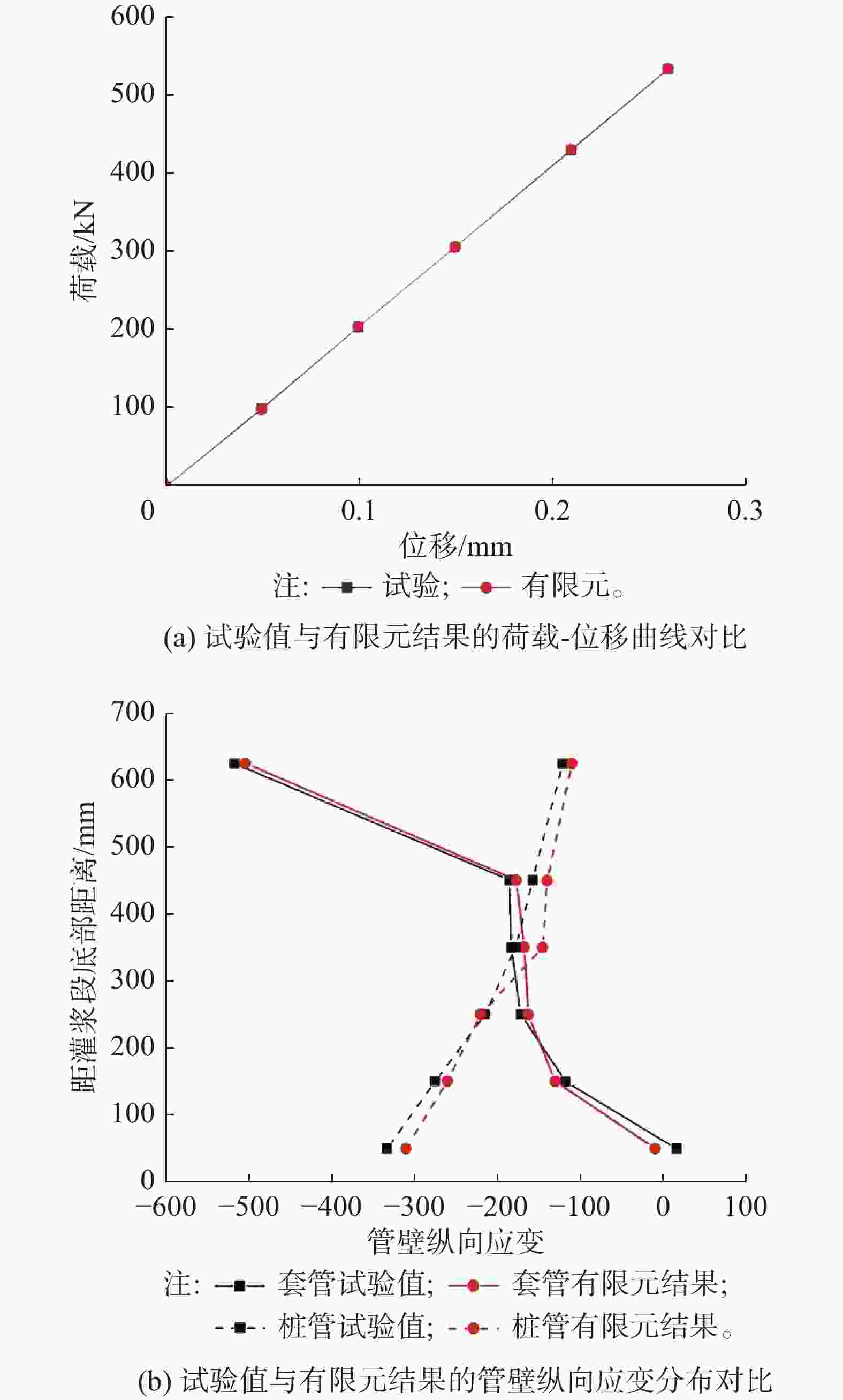
      Figure 11.  Verification comparison between test value and finite element results of standard test piece A-1

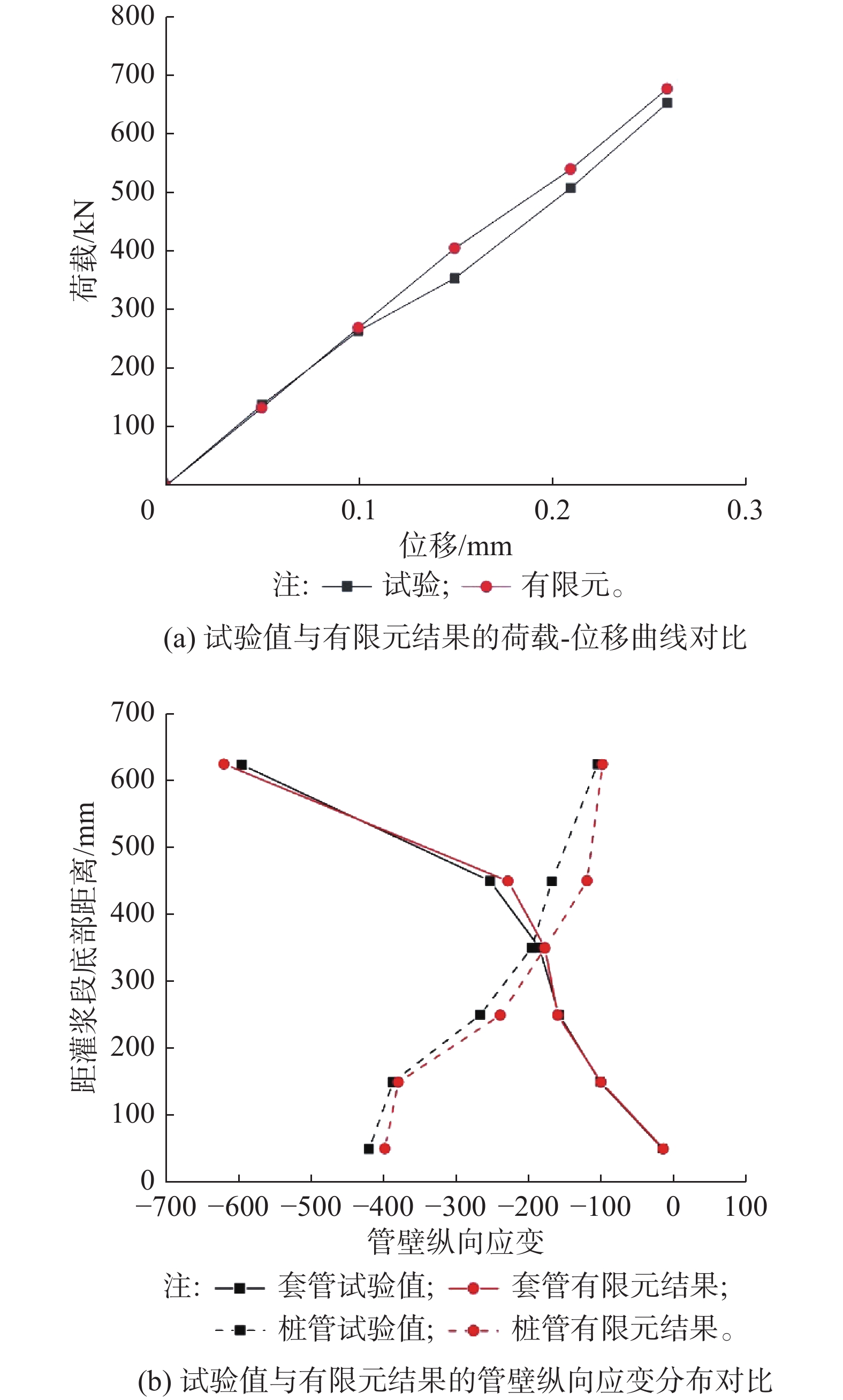
      对于含有纵向安装误差的试件D1A-2,其荷载-位移曲线的相关对比如图12(a)所示,其在最大试验荷载Pmax=696.75 kN下,缩尺试验所测位移值为0.263 mm,有限元模拟的位移值则为0.254 mm,相对误差不超过3.4%,其中误差在大位移情况下较大,其原因可能是含纵向安装误差的试件在进行制备时受到剪力键纵向位置分布不均匀影响,其灌浆区域更容易出现承载薄弱区域,从而导致试件在大荷载下更容易产生较大的破坏与位移。另外,内外钢管管壁的纵向应变(试件90°方向一侧应变)对比结果如图12(b)所示,其套管管壁的纵向应变有限元计算结果与实际试验数据则基本一致,但桩管管壁的纵向应变对比存在一定误差。

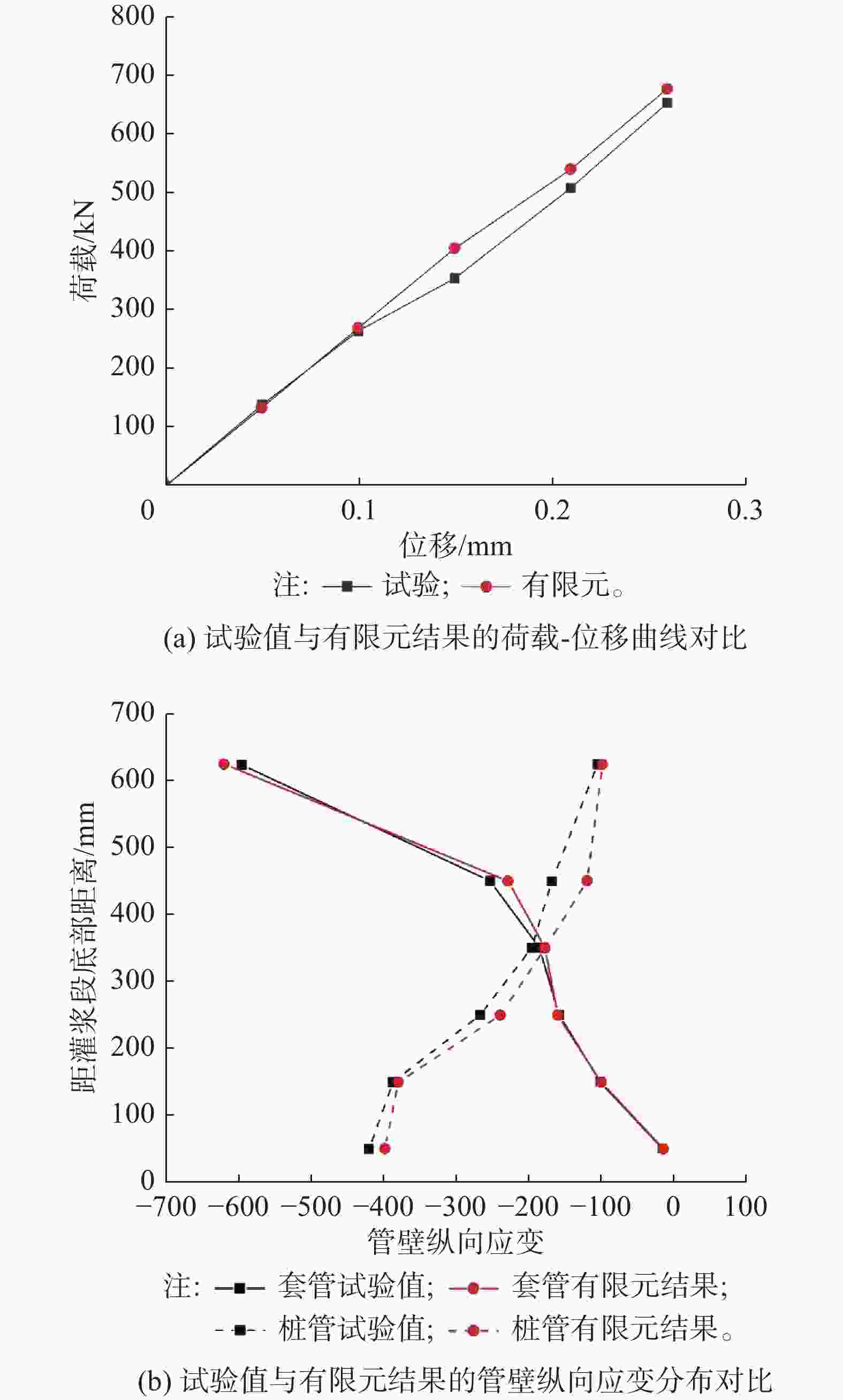
      Figure 12.  Verification comparison between test value and finite element results of longitudinal error test piece D1A-2

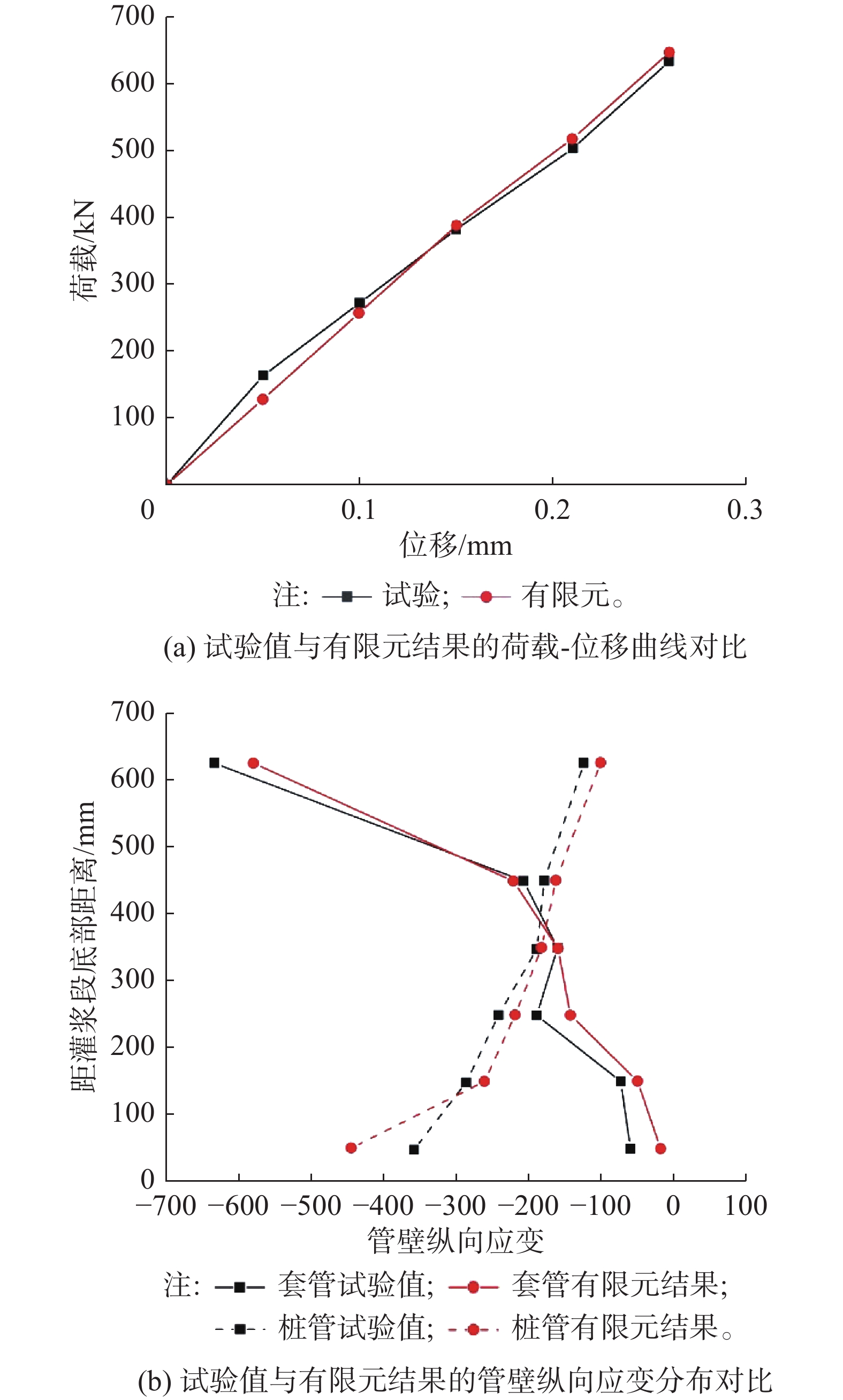
      对于含有横向安装误差的试件D3A-2,其荷载-位移曲线的对比结果如图13(a)所示,其在最大试验荷载Pmax=696.75 kN下,实际试验的位移值为0.273 mm,有限元模拟的位移值为0.267 mm,相对误差不超过2.2%;其内外钢管管壁的纵向应变(试件90°方向一侧应变)对比结果如图13(b)所示,其套管与钢管管壁的纵向应变有限元计算结果与实际试验数据均存在较小误差。

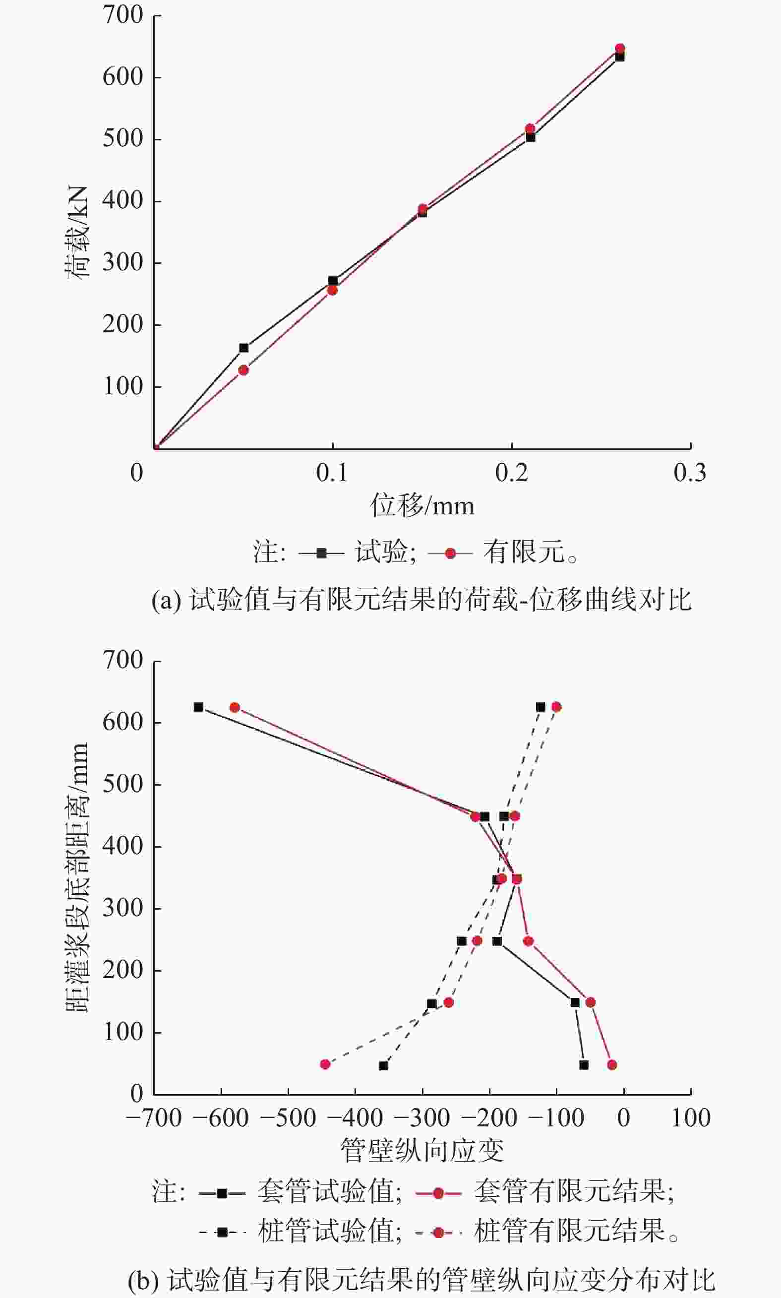
      Figure 13.  Verification comparison between test value and finite element results of transverse error test piece D3A-2

      综上所述,文章所建立的有限元数值模型结果与实际缩尺试验数据的符合性较好,能够有效地反映出灌浆连接段在轴向静力加载过程中的轴向荷载-相对位移曲线以及应变分布特征,这也为之后的参数化研究提供了可靠的分析方法。

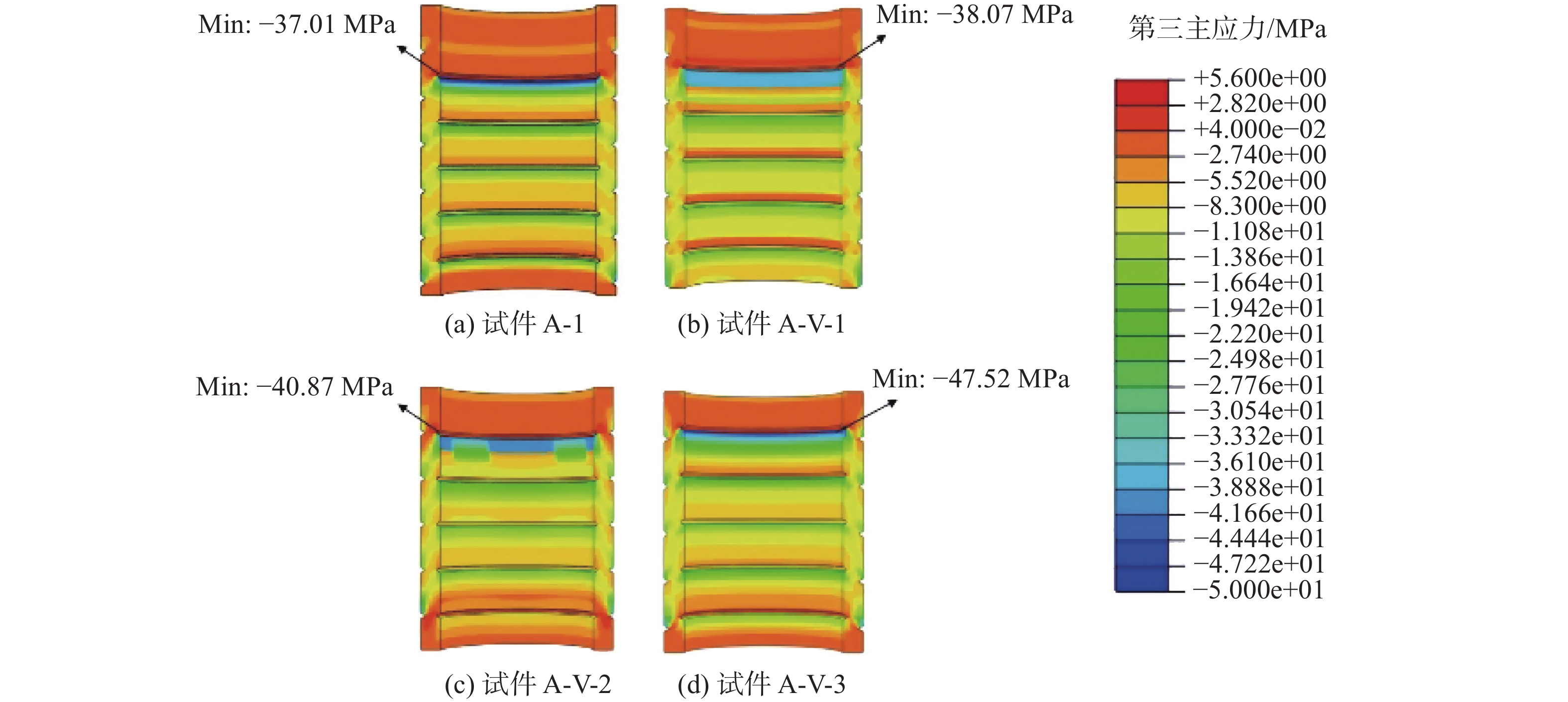
    • 基于有限元数值模型,文章通过调整纵向安装误差参数来分析其对灌浆料应力状态的影响。其中试件A-V-1、A-V-2、A-V-3均是在试件A-1有限元模型的基础上调整纵向安装误差参数所得的数值模型,其纵向相对安装误差v/s分别为0.25、0.50、0.75。

      图14为在轴向压荷载P=422 kN下,不同纵向安装误差的灌浆连接段中灌浆料的第三主应力云图,试件A-1以及误差试件A-V-1、A-V-2、A-V-3的最大第三主应力值分别为37.01 MPa、38.07 MPa、40.87 MPa、47.52 MPa;另外,由图中应力分布的特点可知,最大第三主应力始终出现在套管第一个剪力键处,且其随着横向安装误差的增大而增大,其最大增长率为28.4%。

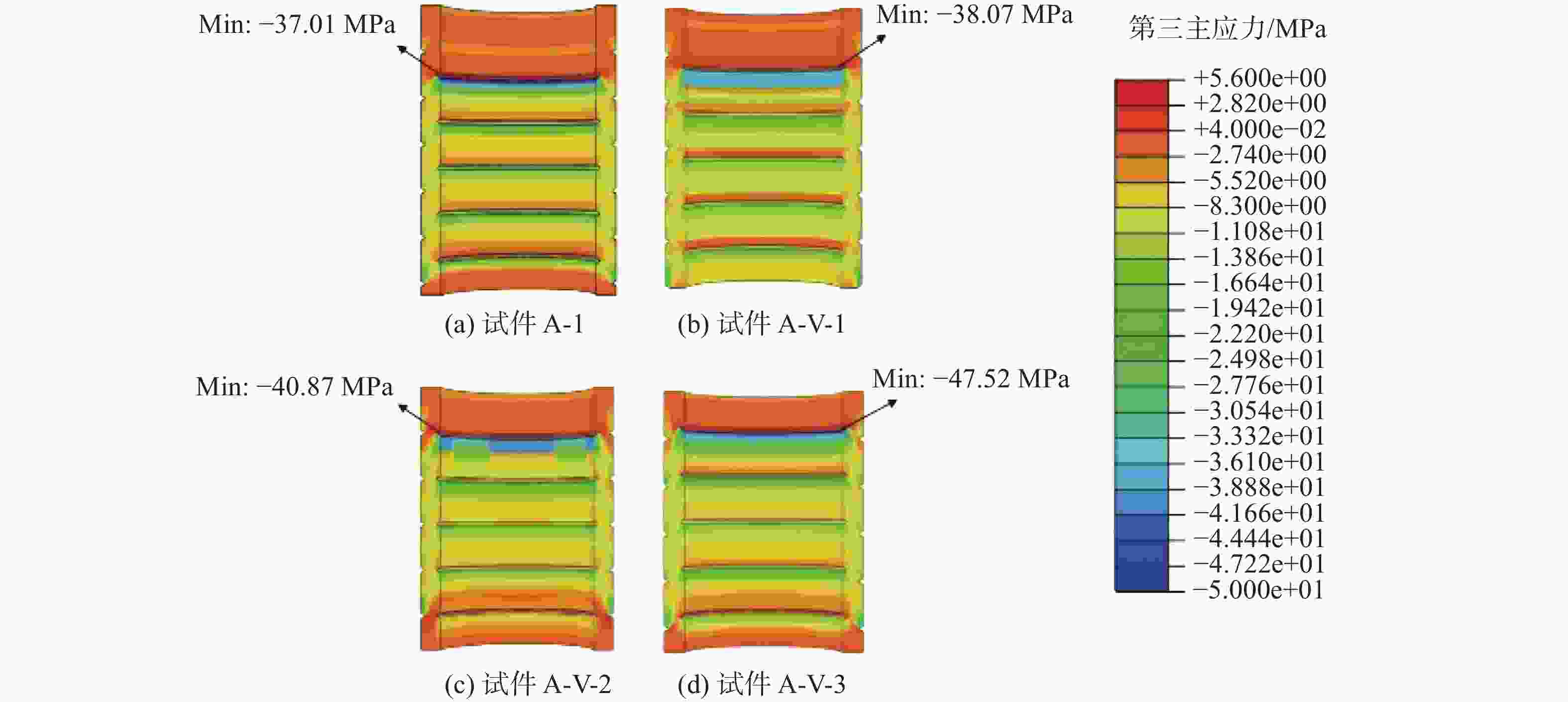
      Figure 14.  Influence of axial installation error on grout stress state

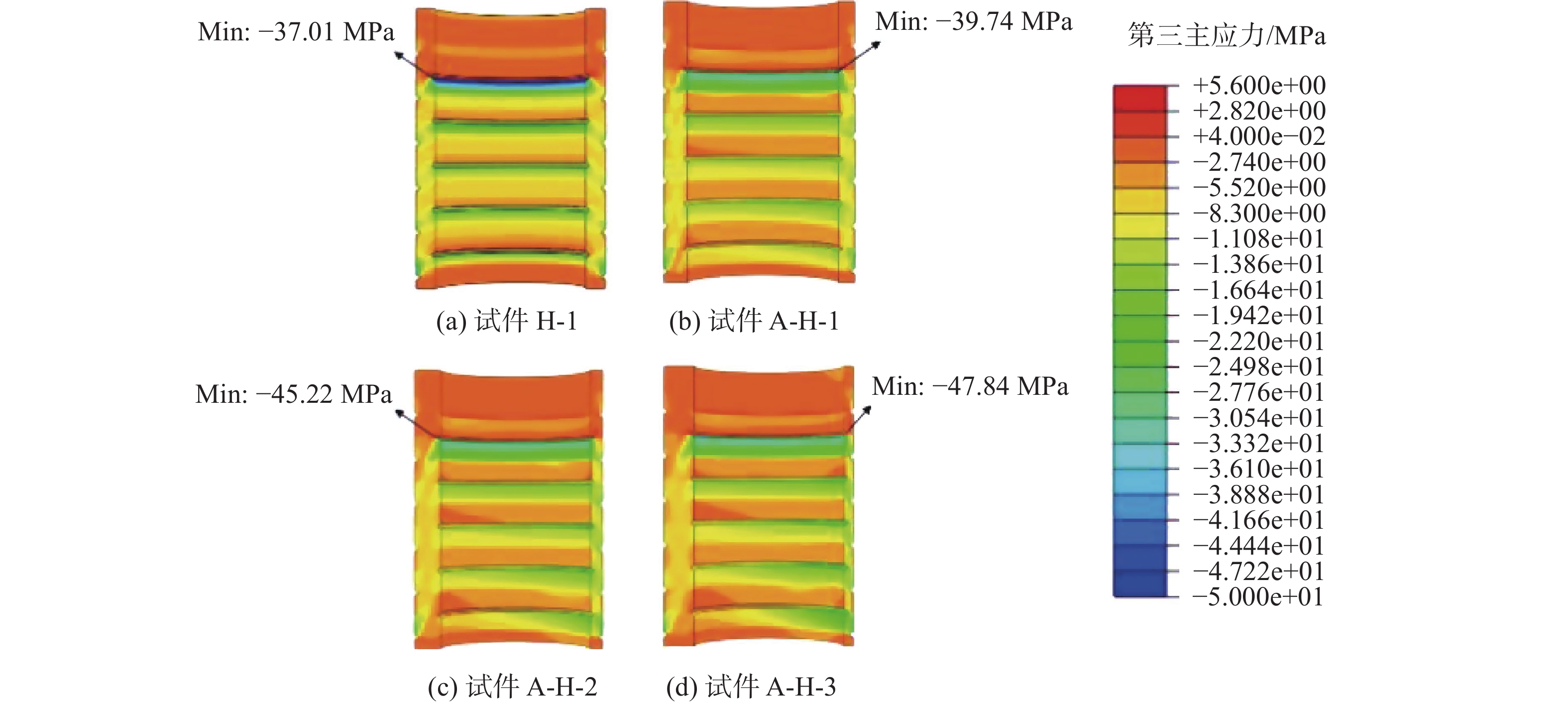
    • 同理,文章也通过调整横向安装误差参数来分析其对灌浆连接段位移、灌浆料应力状态的影响,其中试件A-H-1、A-H-2、A-H-3均是在试件A-1有限元模型的基础上调整横向安装误差参数所得的有限元数值模型,其横向相对安装误差e/tg分别为0.179、0.359、0.538。

      图15为在轴向静力荷载P=422 kN下,不同横向安装误差的灌浆连接段中灌浆料的第三主应力云图,其中试件A-1以及误差试件A-H-1、A-H-2、A-H-3的最大第三主应力值分别为37.01 MPa、39.74 MPa、45.22 MPa、47.84 MPa。而由其最大第三主应力分布特点可知,最大第三主应力主要位于套管上部灌浆料较薄处,并随着横向安装误差的增大而增大,其最大增长率为29.2%。

      Figure 15.  Influence of transverse installation error on grout stress state

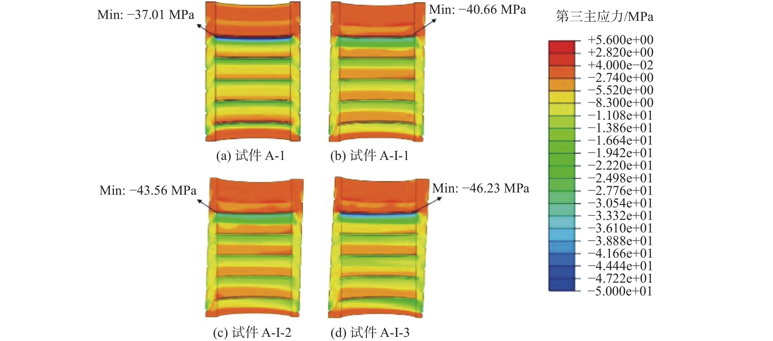
    • 通过有限元数值模型,文章也对于倾斜安装误差对灌浆料应力状态的影响进行了分析和讨论,而试件A-I-1、A-I-2、A-I-3分别是在试件A-1的基础上建立的带有倾斜安装误差的有限元数值模型,其倾斜安装误差i分别为0.7°、1.4°、2.1°。

      图16为在轴向静力荷载P=422 kN下,不同倾斜安装误差的灌浆连接段中灌浆料的第三主应力云图,其中试件A-1以及误差试件A-I-1、A-I-2、A-I-3的最大第三主应力值分别为37.01 MPa、40.66 MPa、43.56 MPa、46.23 MPa。同样由其应力分布特点可知,随着倾斜安装误差的增大,灌浆体中最大第三主应力始终出现在灌浆料上部较薄一侧,并呈现增长趋势,最终在倾斜安装误差达到最大值2.1°时,最大第三主应力达到最大增长率24.9%。

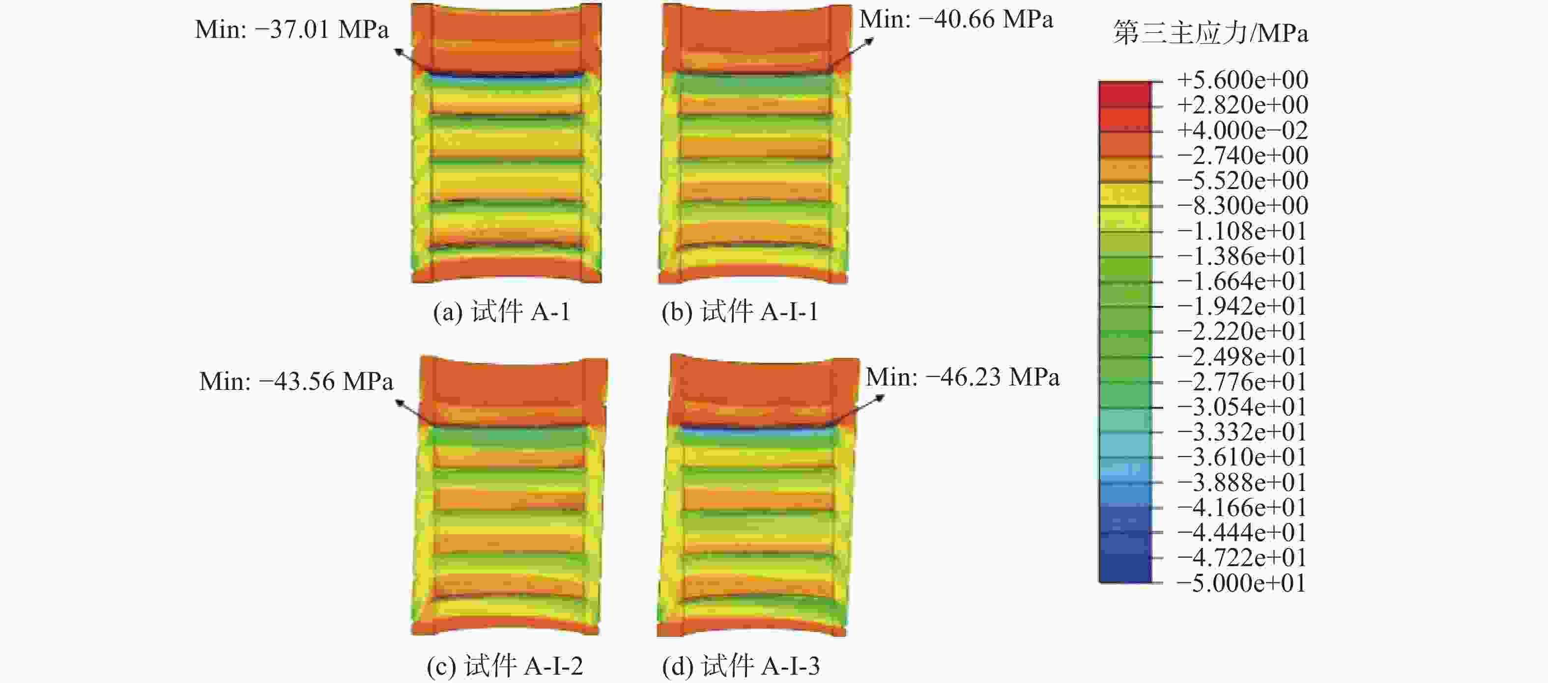
      Figure 16.  Influence of inclined installation error on grout stress state

    • 文章通过缩尺试验揭示了安装误差对于导管架基础灌浆连接段轴向力学性能的影响,并提出了1种可行的有限元数值模拟方法。通过对试验和有限元结果进行总结和分析,文章还进一步得到了以下结论:

      1)灌浆连接段缩尺试件在轴向静力荷载作用下,v/s=0.25的纵向相对安装误差与e/tg=0.375横向相对安装误差使得灌浆连接段的轴向刚度分别增大28%和23%。

      2)在v/s=0.25的纵向相对安装误差影响下,灌浆连接段上下端部纵向应变分别增大了15%和26%;而在e/tg=0.375的横向相对安装误差影响下,灌浆连接段的纵向应变分布发生明显变化,进而可能影响灌浆连接段在轴向加载下的破坏模式。

      3)文章提出的有限元数值模型成功模拟了灌浆连接段的轴向加载过程,并与试验数据取得了较好的拟合性,这为考虑安装误差对灌浆连接段的影响提供了1种有效的评估分析方法。

      4)有限元数值模拟方法表明,在轴向荷载作用下,灌浆连接段中灌浆料的最大第三主应力值随纵向、横向和倾斜安装误差的增大而增大,且其最大第三主应力更有可能出现在灌浆层上部较为薄弱的区域。

Reference (21)

Catalog

    /

    DownLoad:  Full-Size Img  PowerPoint
    Return
    Return