• Peer Review
  • Non-profit
  • Global Open Access
  • Green Channel for Rising Stars
Volume 10 Issue 4
Jul.  2023
Turn off MathJax
Article Contents

WEN Zuopeng, CHENG Fangyuan, CHEN Xuan. Refinement and Calculation Method for Stiffener Scheme for Topside Joints of Offshore Step-Up Station[J]. SOUTHERN ENERGY CONSTRUCTION, 2023, 10(4): 174-183. doi: 10.16516/j.gedi.issn2095-8676.2023.04.018
Citation: WEN Zuopeng, CHENG Fangyuan, CHEN Xuan. Refinement and Calculation Method for Stiffener Scheme for Topside Joints of Offshore Step-Up Station[J]. SOUTHERN ENERGY CONSTRUCTION, 2023, 10(4): 174-183. doi: 10.16516/j.gedi.issn2095-8676.2023.04.018

Refinement and Calculation Method for Stiffener Scheme for Topside Joints of Offshore Step-Up Station

doi: 10.16516/j.gedi.issn2095-8676.2023.04.018
  • Received Date: 2023-01-09
  • Rev Recd Date: 2023-03-13
  • Available Online: 2023-05-26
  • Publish Date: 2023-07-10
  •   Introduction  The topside module of an offshore step-up station usually has numerous tube-I section joints with complicated structure, which cannot be checked by general structural design software. Hence, a feasible checking design method and refinement of stiffener schemes are in need.   Method  A simplified model based on typical tube-I section joints of the topside module of an offshore step-up station was established, and five stiffener schemes were designed for it. Based on the finite element software simulation method, three typical displacement loading conditions, i.e., axial compression displacement, in-plane rotation, and out-of-plane rotation, were applied to analyze the plastic zone development and failure modes of the five stiffener schemes. For the longitudinal stiffener scheme selected, the effective stress section of the stiffener was assumed based on existing codes, and a simplified calculation method for stiffener stress check under complicated loads was proposed. The results were examined using the finite element method.   Result  The results show that the unstiffened tube-I section joint cannot satisfy the design principle of "strong joint and weak member", and it is necessary to take stiffening measures such as stiffeners. The longitudinal stiffener scheme performs better in terms of bearing capacity and economical efficiency. Longitudinal stiffeners are essential for the shearing capacity of beam webs, while the transverse stiffeners cannot enhance shearing capacity. Finite element analysis indicates that the stress distribution is consistent with the assumption of the simplified calculation method, and the simplified calculation method predicts higher stress levels than the finite element results, which means the proposed simplified calculation method is feasible and safer.   Conclusion  The longitudinal stiffener scheme is a better stiffening scheme for the joint. The proposed simplified calculation method can be adopted to check the longitudinal stiffener scheme efficiently.
  • [1] 范少涛, 张力, 王立鹤, 等. 海上升压站的抗震性能分析 [J]. 南方能源建设, 2019, 6(4): 101-105. DOI:  10.16516/j.gedi.issn2095-8676.2019.04.016.

    FAN S T, ZHANG L, WANG L H, et al. Seismic performance analysis of offshore substation [J]. Southern energy construction, 2019, 6(4): 101-105. DOI:  10.16516/j.gedi.issn2095-8676.2019.04.016.
    [2] 张伟, 张坤, 姜贞强, 等. 基于多尺度有限元的海上升压站脚靴式桩套筒连接结构分析研究 [J]. 海洋工程, 2022, 40(2): 55-66. DOI:  10.16483/j.issn.1005-9865.2022.02.006.

    ZHANG W, ZHANG K, JIANG Z Q, et al. Research on the pile-sleeve structure of boot-type offshore substation based on multi-scale finite element method [J]. The ocean engineering, 2022, 40(2): 55-66. DOI:  10.16483/j.issn.1005-9865.2022.02.006.
    [3] 孙震洲, 金伟良, 方滔, 等. 典型海上升压站地震储备承载系数研究 [J]. 海洋工程, 2019, 37(3): 95-101,142. DOI:  10.16483/j.issn.1005-9865.2019.03.011.

    SUN Z Z, JIN W L, FANG T, et al. On the seismic reserve capacity factor of typical offshore substation [J]. The ocean engineering, 2019, 37(3): 95-101,142. DOI:  10.16483/j.issn.1005-9865.2019.03.011.
    [4] 孙震洲, 金伟良, 方滔, 等. 海上升压站在靠船工况下振动舒适性研究 [J]. 海洋工程, 2019, 37(5): 148-155. DOI:  10.16483/j.issn.1005-9865.2019.05.017.

    SUN Z Z, JIN W L, FANG T, et al. On the vibration comfortableness of offshore substation under ship impact conditions [J]. The ocean engineering, 2019, 37(5): 148-155. DOI:  10.16483/j.issn.1005-9865.2019.05.017.
    [5] 杨建军, 俞华锋, 赵生校, 等. 海上风电场升压变电站设计基本要求的研究 [J]. 中国电机工程学报, 2016, 36(14): 3781-3788. DOI:  10.13334/j.0258-8013.pcsee.152761.

    YANG J J, YU H F, ZHAO S X, et al. Research on basic requirements of offshore substation design [J]. Proceedings of the CSEE, 2016, 36(14): 3781-3788. DOI:  10.13334/j.0258-8013.pcsee.152761.
    [6] 钱孟祥, 武韦韦. 海洋平台上部组块节点加强板数值模拟 [J]. 中国造船, 2009, 50(增刊1): 325-332.

    QIAN M X, WU W W. The numerical simulation of offshore platform topside stifferner [J]. Shipbuilding of China, 2009, 50(Suppl. 1): 325-332.
    [7] 任灏, 方辉, 魏鑫泽. 导管架船撞损伤与剩余强度的结构有限元模拟与评估方法 [J]. 南方能源建设, 2021, 8(3): 26-33. DOI:  10.16516/j.gedi.issn2095-8676.2021.03.004.

    REN H, FANG H, WEI X Z. Structural finite element simulation and evaluation method for ship collision damage and residual strength of the jacket [J]. Southern energy construction, 2021, 8(3): 26-33. DOI:  10.16516/j.gedi.issn2095-8676.2021.03.004.
    [8] BAO Q H, FENG H. Finite element simplified fatigue analysis method for a non-tubular joint of an offshore jacket platform [J]. Journal of marine science and application, 2011, 10(3): 321-324. DOI:  10.1007/s11804-011-1075-0.
    [9] SAINI D S, KARMAKAR D, RAY-CHAUDHURI S. A review of stress concentration factors in tubular and non-tubular joints for design of offshore installations [J]. Journal of ocean engineering and science, 2016, 1(3): 186-202. DOI:  10.1016/j.joes.2016.06.006.
    [10] HOSSEINI S A, ZEINODDINI M, DARYAN A S, et al. Model fire tests on a beam-to-leg connection in an offshore platform topside [J]. Fire and materials, 2014, 38(5): 529-549. DOI:  10.1002/fam.2195.
    [11] 井司南. 直接焊接K型、KK型圆钢管节点静力性能的有限元分析 [D]. 哈尔滨: 哈尔滨工业大学, 2009. DOI: 10.7666/d.D270178.

    JIN S N. Finite element analysis on static behavior of directly welded K-type and KK-type CHS-joints [D]. Harbin: Harbin Institute of Technology, 2009. DOI: 10.7666/d.D270178.
    [12] CHEN K M, HUANG H H, WU Q X, et al. Experimental and finite element analysis research on the fatigue performance of CHS K-joints [J]. Engineering structures, 2019, 197: 109365. DOI:  10.1016/j.engstruct.2019.109365.
    [13] 国家经济贸易委员会. 海上固定平台规划、设计和建造的推荐作法——荷载抗力系数设计法(增补1): SY/T 10009—2002 [S]. 北京: 石油工业出版社, 2002.

    State Economic and Trade Commission. Supplement 1 to recommended practice for planning, designing and constructing fixed offshore platform: load and resistance factor design: SY/T 10009—2002 [S]. Beijing: Petroleum Industry Press, 2002.
    [14] 中华人民共和国住房和城乡建设部. 钢结构设计标准: GB 50017—2017 [S]. 北京: 中国建筑工业出版社, 2018.

    Ministry of Housing and Urban-Rural Development of the People's Republic of China. Standard for design of steel structures: GB 50017—2017 [S]. Beijing: China Architecture & Building Press, 2018.
    [15] YOUNG W C, BUDYNAS R G. Roark's formulas for stress and strain (7th ed. ) [M]. New York: McGraw-Hill, 2002.
    [16] LOUCA L A, ALI R M M. Improving the ductile behaviour of offshore topside structures under extreme loads [J]. Engineering structures, 2008, 30(2): 506-521. DOI:  10.1016/j.engstruct.2007.04.020.
    [17] BLODGETT O W. Design of welded structures [M]. Cleveland: James F. Lincoln Arc Welding Foundation, 1966.
    [18] 范云生, 廖君, 洪波. 海上升压站上部组块节点加劲形式数值分析 [J]. 中国水运, 2021, 21(4): 54-56.

    FAN Y S, LIAO J, HONG B. Numerical analysis of offshore platform topside stiffener [J]. China water transport, 2021, 21(4): 54-56.
    [19] AISC. Specification for structural steel buildings: ANSI/AISC 360-16 [S]. Chicago: American Institute of Steel Construction, 2016.
    [20] Det Norske Veritas. Buckling strength analysis: classification notes No. 30.1 [S]. Høvik: Det Norske Veritas, 1992.
  • 通讯作者: 陈斌, bchen63@163.com
    • 1. 

      沈阳化工大学材料科学与工程学院 沈阳 110142

    1. 本站搜索
    2. 百度学术搜索
    3. 万方数据库搜索
    4. CNKI搜索

Figures(14)  / Tables(4)

Article Metrics

Article views(130) PDF downloads(39) Cited by()

Related

Refinement and Calculation Method for Stiffener Scheme for Topside Joints of Offshore Step-Up Station

doi: 10.16516/j.gedi.issn2095-8676.2023.04.018

Abstract:   Introduction  The topside module of an offshore step-up station usually has numerous tube-I section joints with complicated structure, which cannot be checked by general structural design software. Hence, a feasible checking design method and refinement of stiffener schemes are in need.   Method  A simplified model based on typical tube-I section joints of the topside module of an offshore step-up station was established, and five stiffener schemes were designed for it. Based on the finite element software simulation method, three typical displacement loading conditions, i.e., axial compression displacement, in-plane rotation, and out-of-plane rotation, were applied to analyze the plastic zone development and failure modes of the five stiffener schemes. For the longitudinal stiffener scheme selected, the effective stress section of the stiffener was assumed based on existing codes, and a simplified calculation method for stiffener stress check under complicated loads was proposed. The results were examined using the finite element method.   Result  The results show that the unstiffened tube-I section joint cannot satisfy the design principle of "strong joint and weak member", and it is necessary to take stiffening measures such as stiffeners. The longitudinal stiffener scheme performs better in terms of bearing capacity and economical efficiency. Longitudinal stiffeners are essential for the shearing capacity of beam webs, while the transverse stiffeners cannot enhance shearing capacity. Finite element analysis indicates that the stress distribution is consistent with the assumption of the simplified calculation method, and the simplified calculation method predicts higher stress levels than the finite element results, which means the proposed simplified calculation method is feasible and safer.   Conclusion  The longitudinal stiffener scheme is a better stiffening scheme for the joint. The proposed simplified calculation method can be adopted to check the longitudinal stiffener scheme efficiently.

WEN Zuopeng, CHENG Fangyuan, CHEN Xuan. Refinement and Calculation Method for Stiffener Scheme for Topside Joints of Offshore Step-Up Station[J]. SOUTHERN ENERGY CONSTRUCTION, 2023, 10(4): 174-183. doi: 10.16516/j.gedi.issn2095-8676.2023.04.018
Citation: WEN Zuopeng, CHENG Fangyuan, CHEN Xuan. Refinement and Calculation Method for Stiffener Scheme for Topside Joints of Offshore Step-Up Station[J]. SOUTHERN ENERGY CONSTRUCTION, 2023, 10(4): 174-183. doi: 10.16516/j.gedi.issn2095-8676.2023.04.018
    • 我国海上风力资源储备丰富,具备较高的开发价值。目前我国的海上风电已进入快速发展时期,保障海上风电系统的结构安全对风力发电事业至关重要。海上升压站是海上风电的核心结构,由上部组块、下部导管架组成[1-3]。对于海上升压站,一般通过结构设计软件进行整体结构的设计,并通过有限元软件或基于规范的简化方法进行细部节点的校核[4-6]。海上升压站结构中大量杆件互相连接[7],形成数量众多的不同类型节点,例如环板节点、管节点、圆管-工字钢节点[8-10]。其中,管节点已有大量试验、理论研究[11-12]和规范规定计算方法[13-14],设计手段较为成熟,环板节点也有相应的简化计算方法[15]。圆管-工字钢节点构造形式多样,受力情况较为复杂,难以用规范直接进行验算。因此圆管-工字钢节点的合理设计是上部组块结构设计的一大难点。

      在钢框架结构中,一般会在与斜撑相接的梁翼缘下方设置加劲肋对节点进行加强。加劲肋的形式多样,包括横向加劲肋、纵向加劲肋、弧形加劲肋等[16-17]。由于构造相对复杂,内力分布模式不明确,目前缺乏规范规定,只能通过有限元方法或简化计算方法进行设计校核。对于对工字钢-工字钢斜撑节点,Blodgett[17]在特定配置下给出了纵向加劲肋、横向加劲肋的应力简化计算方法。对于圆管-工字钢节点加劲肋的研究较少[6,18]。圆管-工字钢节点常用加劲肋配置包括横向加劲肋、纵向加劲肋,其中纵向加劲肋对于加强节点抗剪承载力相当重要。现有研究仅限于对配置横向加劲肋的节点进行简化计算校核[6],而未有对含纵向加劲肋的节点构造进行简化计算的方法。要对加劲肋节点进行简化计算,则需明确斜撑集中力作用下加劲肋的有效受力面积。对于翼缘集中力作用下的腹板,相关规范[14,19-20]给出了规定荷载扩散角的坡度比。这种针对腹板的简化计算方法也被应用于加劲肋的计算[17],但当加劲肋构造较为复杂时,该方法的适用性存疑。

      圆管-工字钢节点加劲肋的构造方案有多种选择,而不同方案的承载能力、用钢量是不同的。上部组块的圆管-工字钢节点数量众多,因此需要考虑其经济性和计算效率,对不同方案优劣进行比较分析,并探索简化计算方法。

      本文选取海上升压站上部组块节点的简化模型,采用Ansys有限元软件对圆管-工字钢节点的多种加劲肋加强方案研究受力状态与破坏形式。选取纵向加劲肋方案,提出加劲肋的应力简化计算方法,据此对加劲肋方案进行快速校核。最后,通过有限元分析验证内力分布假定合理性与简化计算方法的有效性。

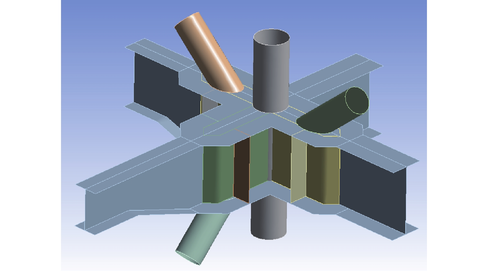
    • 一个典型的圆管-工字钢节点如图1所示。为研究圆管-工字钢节点的破坏模式,有必要对节点进行简化。在柱子不出现塑性的情况下,各横梁的受力状态不影响其他横梁的受力模式。因此,可将该节点截断,简化模型如图2所示。

      Figure 1.  Typical tube-I section joint of offshore step-up station

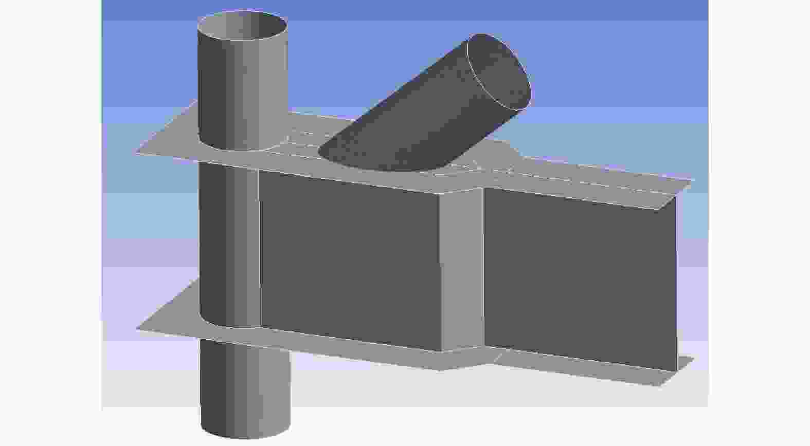
      Figure 2.  Simplified tube-I section joint

      采用Ansys命令流方式对带加劲肋的节点进行有限元分析。不同部件间的连接处自动创建共享节点,实现共同受力协调变形。考虑到节点模型各部件均为薄壁构件,采用SHELL181壳单元对几何模型进行网格划分,平均网格尺寸为0.2 m。材料弹性模量为E=$2.1 \times {10^{11}}$ Pa,屈服强度为$f_y$=345 MPa,屈服后弹性模量为0。

      对节点模型选用工程中典型的几何参数,如表1所示。斜撑与横梁夹角θ设为40o

      参数数值/mm
      立柱直径$ \times $壁厚 406$ \times $24
      横梁高度(h)$ \times $宽度(b)$ \times $腹板厚度(tw)$ \times $翼缘厚度(tf) 800$ \times $400$ \times $16$ \times $36
      斜撑直径(D)$ \times $壁厚(t) 406$ \times $24
      斜撑与立柱最小间隙(g) 100
      加劲肋厚度(ts) 16
      节点板半宽 360

      Table 1.  Geometric parameters of the joint model

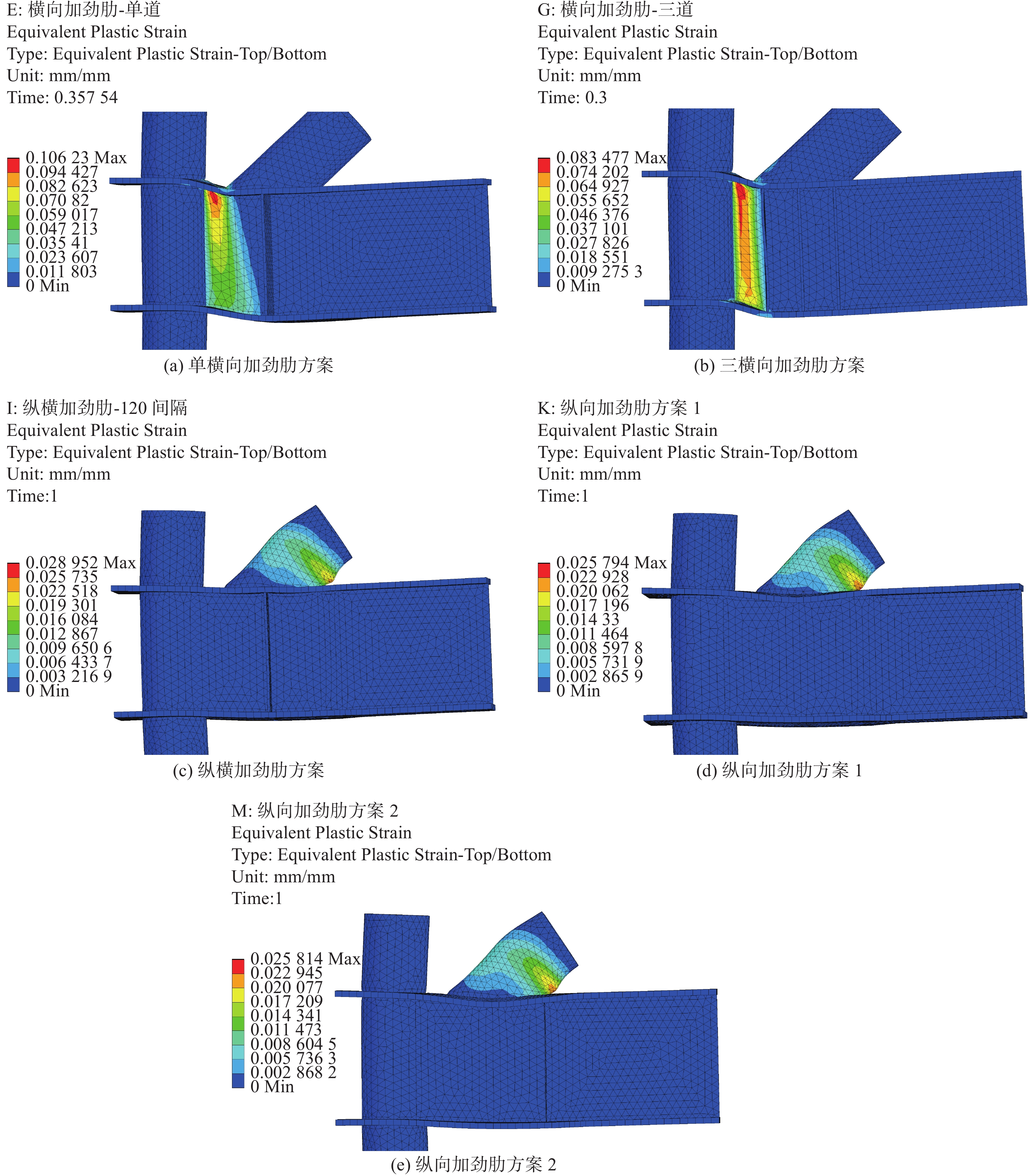
      研究对象包括5种节点加劲肋方案,如图3所示。横向加劲肋是在海上平台结构节点的典型构造,分别设置了一道、三道加劲肋。对于包含纵向加劲肋的构造设置了3种方案:纵横加劲肋、纵向加劲肋-1、纵向加劲肋-2。

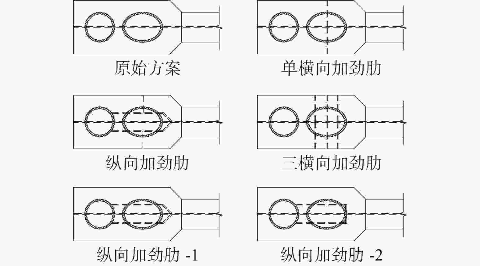
      Figure 3.  Stiffener schemes of the joint

      在海上升压站中,斜撑与横梁的焊接可视为刚接,该连接能传递弯矩。本文的极限工况采用3种位移加载方式,分别为轴压位移、面外转角、面内转角。模型边界条件与加载条件的简图如图4所示,图4(a)给出了斜撑端部的局部坐标系。

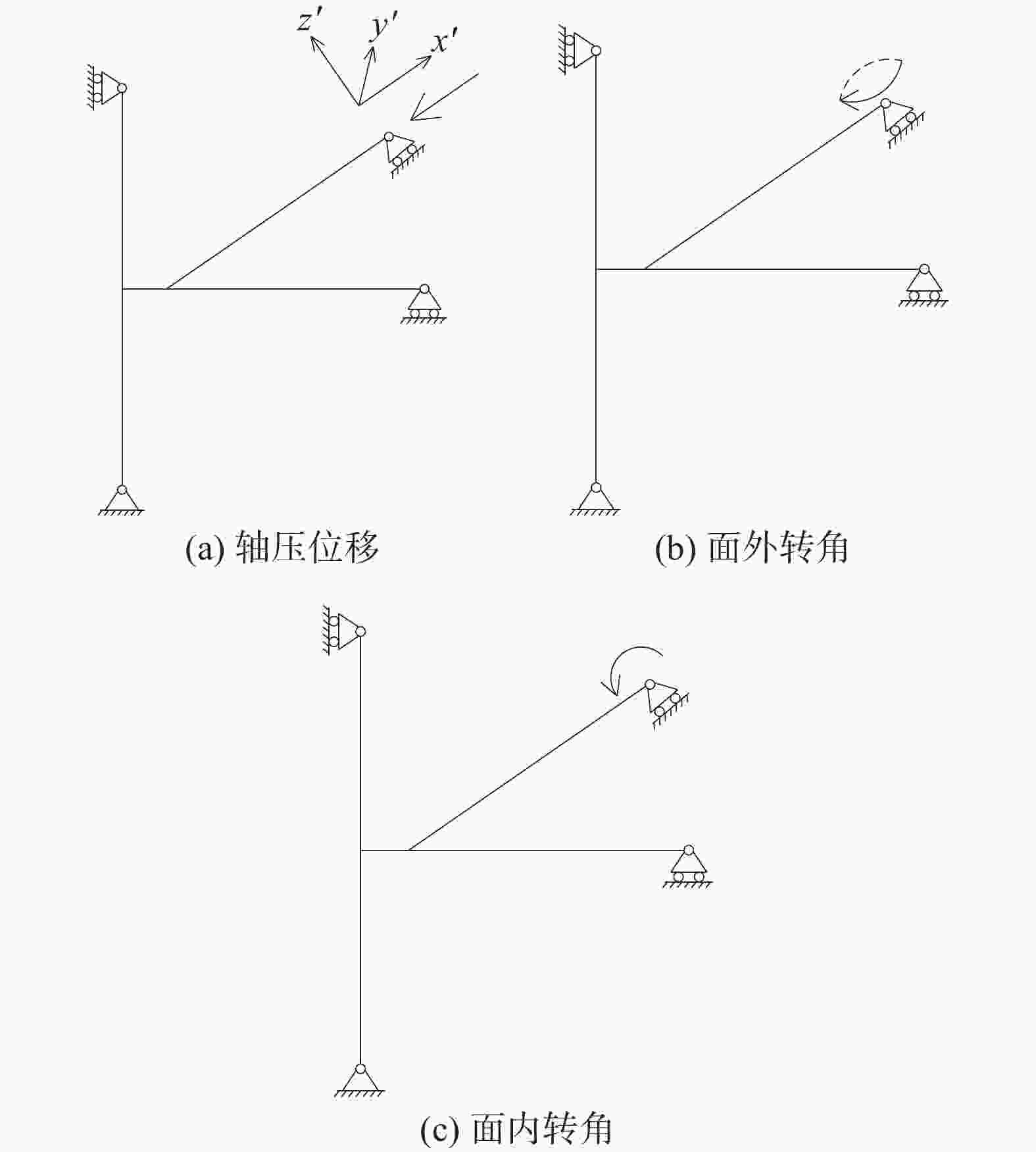
      Figure 4.  Diagram of boundary conditions and loading conditions of the joint

    • 对各加劲肋方案的有限元分析结果如表2所示。针对无加劲肋原始方案,图5给出在不同加载条件下的塑性应变云图。考虑到轴压加载条件下各方案的塑性应变结果差异相对较大,故图6给出轴压作用下各加劲肋方案的塑性应变云图。下面分别对3种加载工况的结果进行分析。

      加劲肋方案加载工况
      轴压位移面外转角面内转角
      原始方案

      腹板近柱侧、斜撑端部塑性;
      腹板剪切变形过大(×)
      腹板顶端、斜撑与柱子之间翼缘塑性;
      翼缘板转动变形过大(×)
      斜撑塑性;斜撑面内转角过大(√)
      单横向加劲肋
      腹板近柱侧;腹板剪切变形过大(×)斜撑塑性;斜撑面外转角过大(√)斜撑塑性;斜撑面内转角过大(√)
      三横向加劲肋
      腹板近柱侧塑性;腹板剪切变形过大(×)斜撑塑性;斜撑面外转角过大(√)斜撑塑性;斜撑面内转角过大(√)
      纵横加劲肋
      斜撑塑性;斜撑轴向变形过大(√)斜撑塑性;斜撑面外转角过大(√)斜撑塑性;斜撑面内转角过大(√)
      纵向加劲肋1
      斜撑塑性;斜撑轴向变形过大(√)斜撑塑性;斜撑面外转角过大(√)斜撑塑性;斜撑面内转角过大(√)
      纵向加劲肋2
      斜撑塑性;斜撑轴向变形过大(√)斜撑塑性;斜撑面外转角过大(√)斜撑塑性;斜撑面内转角过大(√)
      注:×表示不满足“强节点弱构件”,√表示满足。

      Table 2.  Failure modes of stiffener schemes under different loading conditions

      Figure 5.  Plastic strain contour of the joint without stiffeners in failure status

      Figure 6.  Plastic strain contour of the joint in different schemes in failure status under axial load

      1)轴压位移工况

      对于无加劲肋节点,在轴压位移作用下,柱子与斜撑之间的梁腹板承受较高的剪力,很快进入塑性状态,腹板变形过大,表明原始方案不满足“强节点、弱构件”原则。横向加劲肋方案中,柱子与斜撑之间的梁腹板受剪力作用先于斜撑进入塑性状态。这是由于横向加劲肋无法分担柱子与斜撑之间腹板所承受的剪力。对于纵向加劲肋、纵横加劲肋方案,由于纵向加劲肋分担了腹板的剪力,斜撑先出现塑性,满足“强节点、弱构件”原则。

      2)面外转角工况

      对于无加劲肋方案,由于翼缘缺乏翼缘面外支撑,翼缘绕腹板顶端产生转动,引起腹板顶端、翼缘的塑性。对于横向加劲肋方案,单片横向加劲肋出现塑性,而3片加劲肋的构造则只出现了斜撑的塑性破坏,这表明单片横向加劲肋可能不够安全。纵向加劲肋、纵横加劲肋方案则表现出对翼缘的充分支撑,仅有斜撑塑性破坏。

      3)面内转角工况

      对于无加劲肋方案、单横向加劲肋方案,斜撑下方翼缘在近、远两个端点附近早期发展塑性,随后逐渐扩散,表明其无法提供有效支撑。3片横向加劲肋、纵向加劲肋、纵横加劲肋方案的结果均为斜撑塑性破坏,表明这些方案能够提供有效的支撑。

      在上述方案中,纵横加劲肋方案、纵向加劲肋方案1和方案2均能实现“强节点弱构件”的设计目标。考虑到缺乏次级横向加劲肋的纵向加劲肋方案在前述配置条件下已能满足承载力要求,次级横向加劲肋可能是赘余的。因此,有必要探究纵向加劲肋方案在何种条件下能够满足承载力要求。方案2的端部横向加劲肋比方案1的斜向加劲肋距离加载中心更近,能够提供更大的支撑刚度,因此下面基于纵向加劲肋方案2展开深化研究。

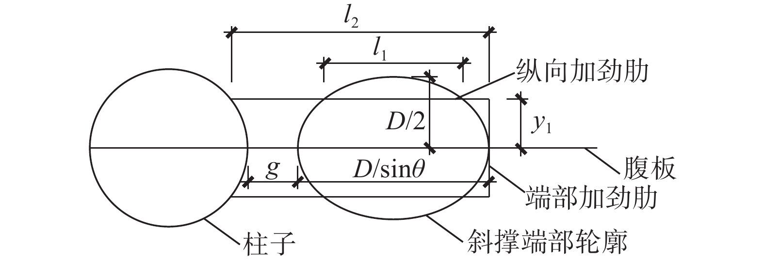
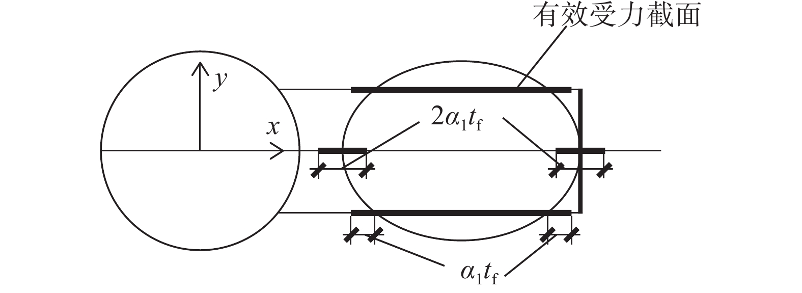
    • 根据前文结果,针对纵向加劲肋方案2给出简化计算方法,并进行方案优化。计算相关几何参数如图7所示。斜撑的荷载传递至翼缘后,由翼缘下方的梁腹板和加劲肋共同承担。假定参与受力的梁腹板、加劲肋有效截面如图8所示。对于端部加劲肋和位于斜撑椭圆轮廓内的纵向加劲肋,当其与斜撑轮廓位置足够接近时,可认为其全截面参与受力。另外,集中力荷载下方荷载存在扩散角,坡度比可取为1∶${\alpha _1}$,其中${\alpha _1} = \sqrt 3 $[20]

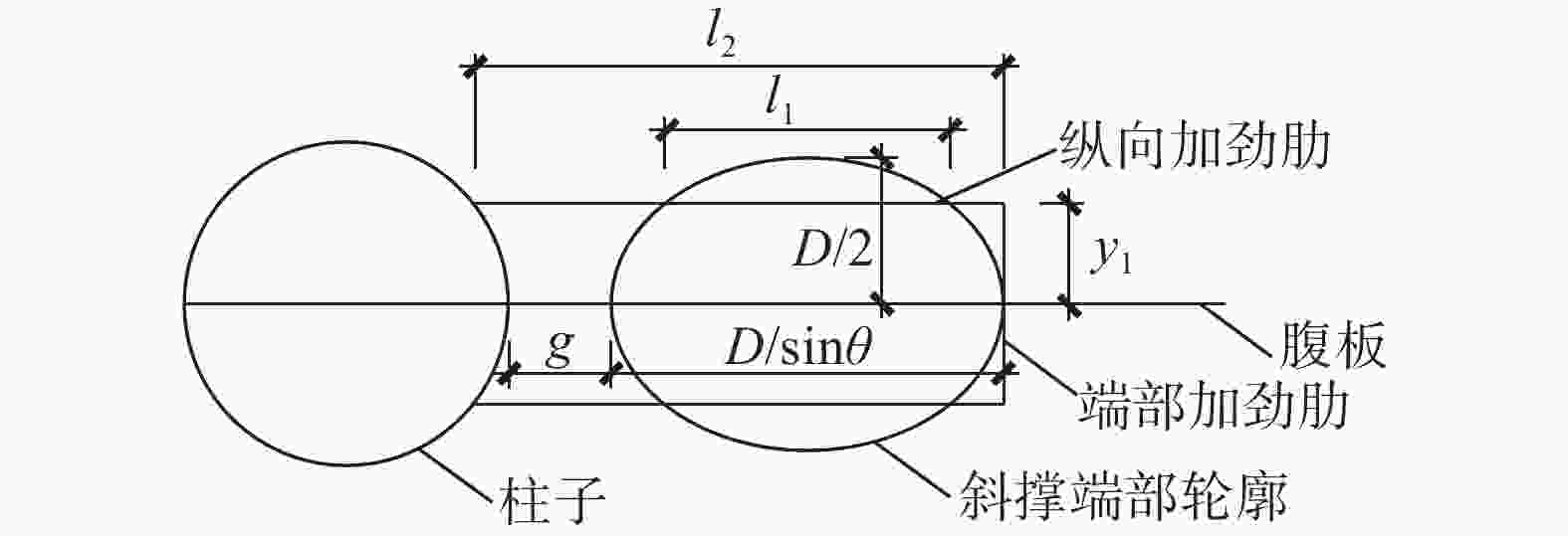
      Figure 7.  Joint calculation related geometric parameters

      Figure 8.  Effective section of web and stiffener (${\alpha _1} = \sqrt 3 $

      记加劲肋有效截面的截面积为${A_{{\text{eff}}}}$,对xy方向中性轴的惯性矩分别为${I_x}$${I_y}$,其中${A_{{\text{eff}}}}$表达式为

      $$ {A_{{\text{eff}}}} = 2{t_{\text{s}}}\left( {{l_1} + 2\sqrt 3 {t_{\text{f}}} + {y_1}} \right) $$ (1)

      采用DNV规范[20]对纵向加劲肋的屈曲承载力校核。加劲肋的弹性屈曲应力、屈曲承载强度分别为:

      $$ {\sigma _{\text{E}}} = C\dfrac{{{{\text{π}}^2}E}}{{12\left( {1 - {\nu ^2}} \right)}}{\left( {\dfrac{{{t_{\text{s}}}}}{{{l_2}}}} \right)^2}, {\sigma _{{\text{scr}}}} = \dfrac{{{f_{y}}}}{{\sqrt {1 + {{\left( {{f_{y}}/{\sigma _{E}}} \right)}^4}} }} $$ (2)

      式中:

      E——弹性模量;

      ν ——泊松比;

      C——系数,根据荷载形式参照DNV规范[20]表3.2取值。

      对于真实内力加载的工况,设斜撑端部在其局部坐标系(见图4)内的荷载为${F_x}$${F_y}$${F_z}$${M_x}$${M_y}$${M_z}$。对各荷载的效应进行线性叠加,则纵向加劲肋顶部竖向应力表达式为:

      $$ {\sigma _1} = \frac{{{F_x}\sin \theta + {F_y}\cos \theta }}{{2{t_{\text{s}}}\left( {{l_1} + 2\sqrt 3 {t_{\text{f}}} + {y_1}} \right)}} + \frac{{{M_x}{y_1}\cos \theta }}{{{I_x}}} + \frac{{{M_z}{y_1}\sin \theta }}{{{I_x}}} + \frac{{{M_y}}}{{{I_y}}}{x_1} $$ (3)

      式中:

      x1 ——加劲肋上某点至y向中性轴距离。

      为考察单位移加载模式下极限承载力,分别给出轴压位移、面外转角、面内转角工况下加劲肋顶部竖向应力指标的表达式如下:

      $$ \begin{array}{c} 轴压位移:{\sigma _1} = \dfrac{{{F_x}\sin \theta }}{{2{t_{\text{s}}}\left( {{l_1} + 2\sqrt 3 {t_{\text{f}}} + {y_1}} \right)}}\\ 面外转角:{\sigma _1} = \dfrac{{{M_x}{y_1}\sin \theta }}{{{I_x}}}\\ 面内转角:{\sigma _1} = \dfrac{{{M_y}}}{{{I_y}}}{x_1} \end{array} $$ (4)

      另外,在柱子与斜撑之间,加劲肋与梁腹板的平均剪应力为:

      $$ {\sigma _{\text{v}}} = \frac{{{F_x}\sin \theta }}{{{h_{\text{w}}}\left( {{t_{\text{w}}} + 2{t_{\text{s}}}} \right)}} $$ (5)

      若忽略端部加劲肋、集中力下方扩散面积对弯矩承载力的贡献,面外转角工况中纵向加劲肋的竖向应力可简化表达为:

      $$ {\sigma _1} \approx \frac{{{M_x}\sin \theta }}{{2{y_1}{t_{\text{s}}}{l_1}}} $$ (6)

      由椭圆的几何性质易知,${y_1}$${l_1}$存在负相关关系,且当${y_1} = \sqrt 2 D/4$${l_1} = \sqrt 2 D/\left( {2\sin \theta } \right)$时,可实现${y_1}{\text{、}}{l_1}$的最大值。此时可实现加劲肋应力最小值,即对应加劲肋的最优位置。

    • 下面根据简化计算方法分别对极限加载工况、真实荷载工况下的加劲肋配置进行校核。根据3.1节,采用纵向加劲肋最优位置,即${y_1} = \sqrt 2 D/4$${l_1} = \sqrt 2 D/\left( {2\sin \theta } \right)$。相关计算参数沿用第2章的设置。

      对于极限状态的判断,轴压工况取斜撑全截面进入塑性,从而对应轴力极限荷载为9 932 kN;面内转角、面外转角工况取斜撑边缘进入塑性,从而对应弯矩极限荷载为89.6 kNm。对于真实荷载工况,采用SACS软件对升压站上部组块模型进行整体分析,提取典型节点的斜撑端部荷载六分量,如表3所示。简化计算方法给出的各工况应力结果如表4所示。表4的简化方法结果将用于与有限元结果的对比。

      ${F_x}$/kN${F_y}$/kN${F_z}$/kN${M_x}$/kNm${M_y}$/kNm${M_z}$/kNm
      1 571.44.9−1.5−11.85.710.1

      Table 3.  Loads at the end of brace member under true loading conditions

      加载工况指标数值/MPa
      屈曲承载强度${\sigma _{{\text{scr}}}}$ 342.5
      抗剪强度${f_{\text{v}}}$ 199.2
      极限加载工况 轴压位移 竖向应力${\sigma _1}$ 235.4<${\sigma _{{\text{scr}}}}$
      剪应力${\sigma _{\text{v}}}$ 182.6<${f_{\text{v}}}$
      面外转角 竖向应力${\sigma _1}$ 204.2<${\sigma _{{\text{scr}}}}$
      面内转角 竖向应力${\sigma _1}$ 193.9<${\sigma _{{\text{scr}}}}$
      真实荷载工况 竖向应力${\sigma _1}$ 43.9<${\sigma _{{\text{scr}}}}$
      剪应力${\sigma _{\text{v}}}$ 28.9<${f_{\text{v}}}$

      Table 4.  Calculated stress values of stiffener under different loading conditions

      计算表明,真实荷载工况下加劲肋能够满足承载力要求。该方案能够满足轴压、面内转角、面外转角等工况的极限承载力要求,实现“强节点弱构件”的设计。若所采用的加劲肋参数不满足要求,则可加大加劲肋厚度,或者增设次级横向加劲肋(参见纵横加劲肋方案或文献[18]),从而分担荷载并增强对纵向加劲肋的支撑。

    • 采用Ansys软件进行各加载工况的模拟,对简化计算方法的假定与结果进行验证。

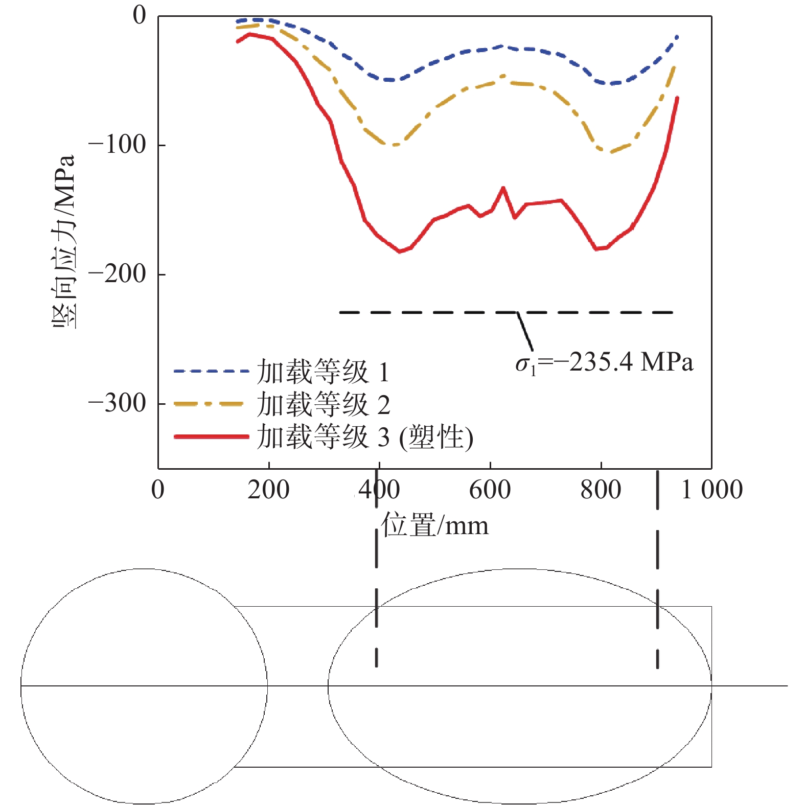
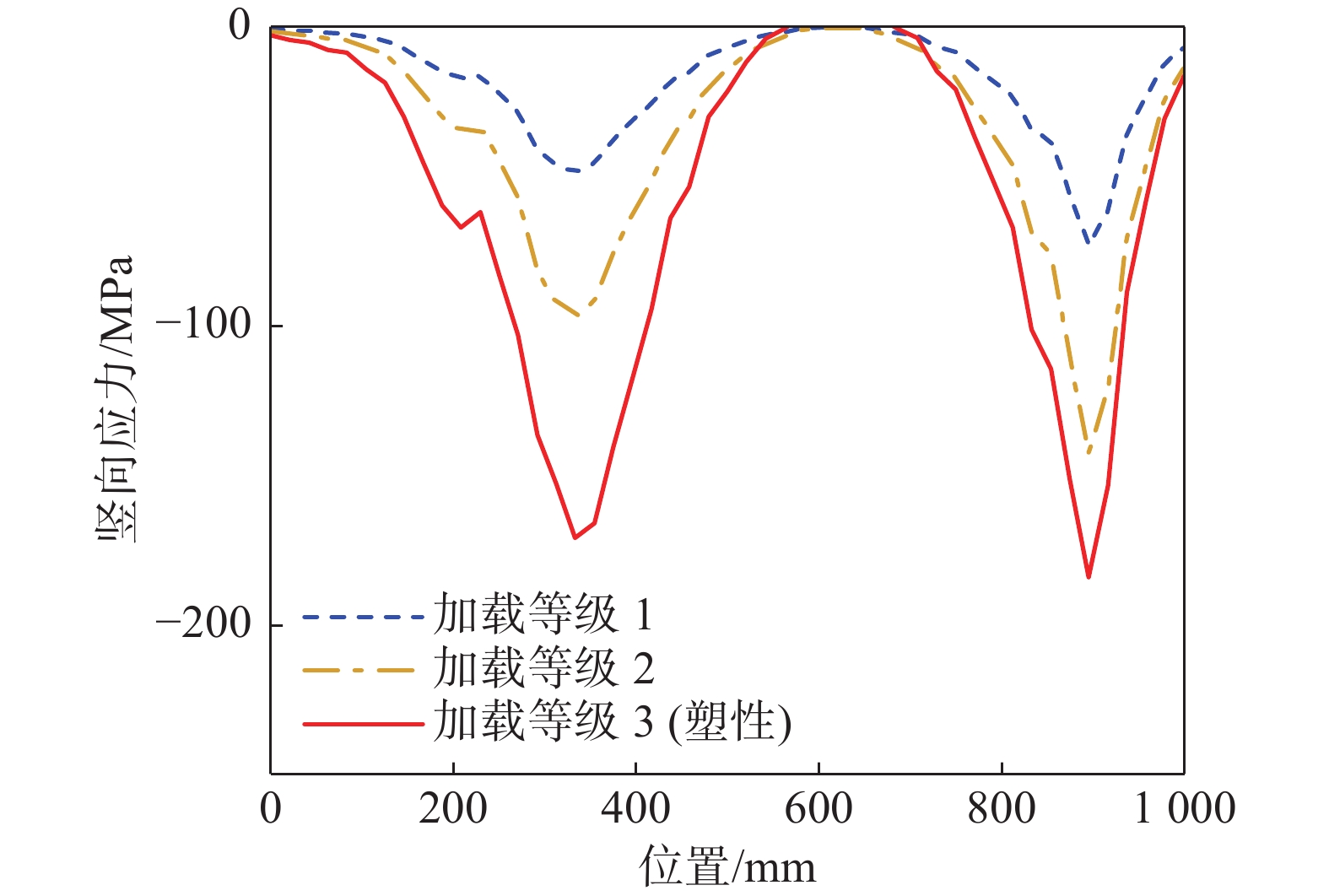
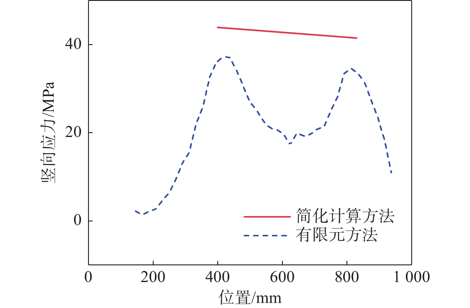
      对于轴压位移工况,纵向加劲肋顶部竖向应力沿纵向的分布如图9所示。为便于观察应力水平增长过程中应力分布的演变情况,图中分别给出从低到高加载等级1、加载等级2、加载等级3对应的应力结果,其中加载等级3对应斜撑初始进入塑性的阶段。图9表明,在斜撑与加劲肋的两个接触点处的应力水平较高;在两接触点之间依然具有较高应力水平,不应被忽略。因此,简化计算方法所假定的纵向加劲肋的有效受力截面是合理的;在受力分析时若仅考虑集中力下方扩散角范围内的加劲肋截面,则与实际受力情况不符。另外,图中也给出简化计算方法给出的应力σ1数值曲线,发现其绝对值大于有限元结果,这表明简化计算方法是偏安全的。腹板顶部竖向应力沿纵向的分布如图10所示。图10表明,在斜撑与腹板的两个接触点之间,腹板顶部应力逐渐衰减至趋近于零,这与前文假定是相符的。

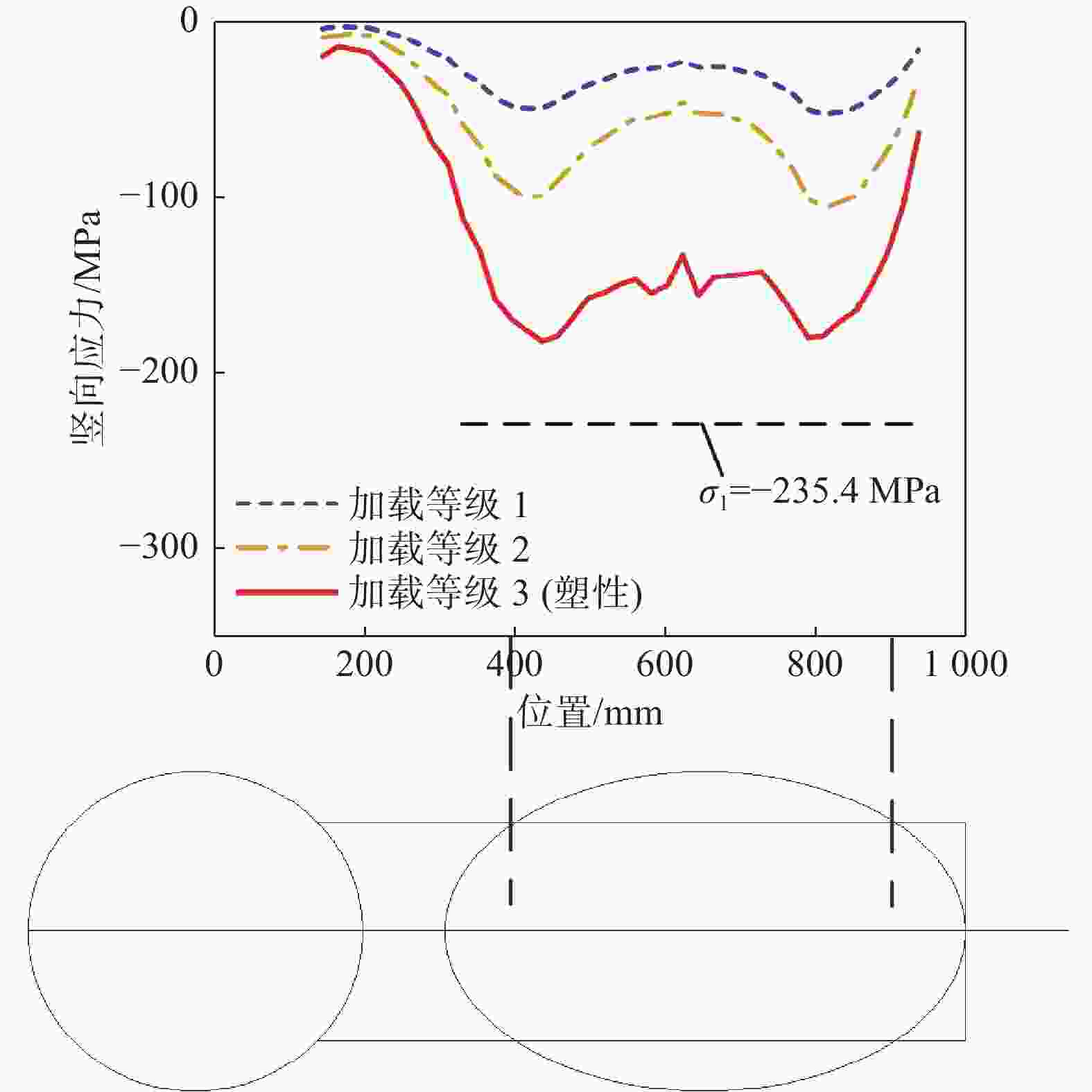
      Figure 9.  Vertical stress distribution at the top of longitudinal stiffener under axial loading condition

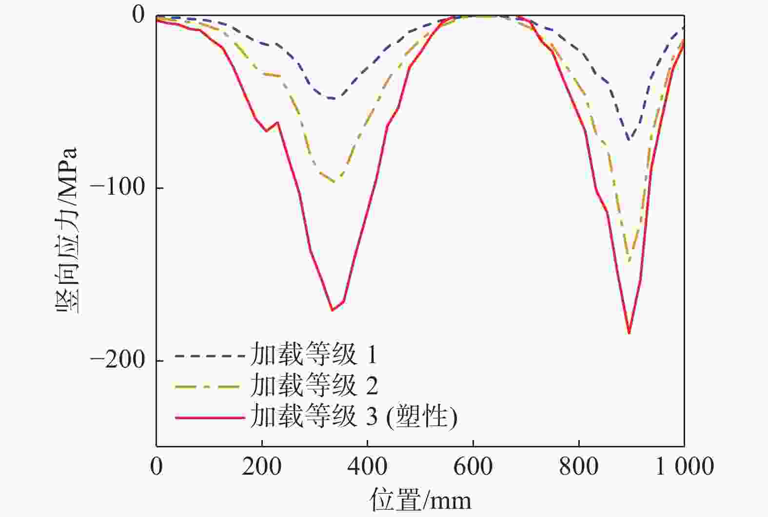
      Figure 10.  Vertical stress distribution at the top of web under axial loading condition

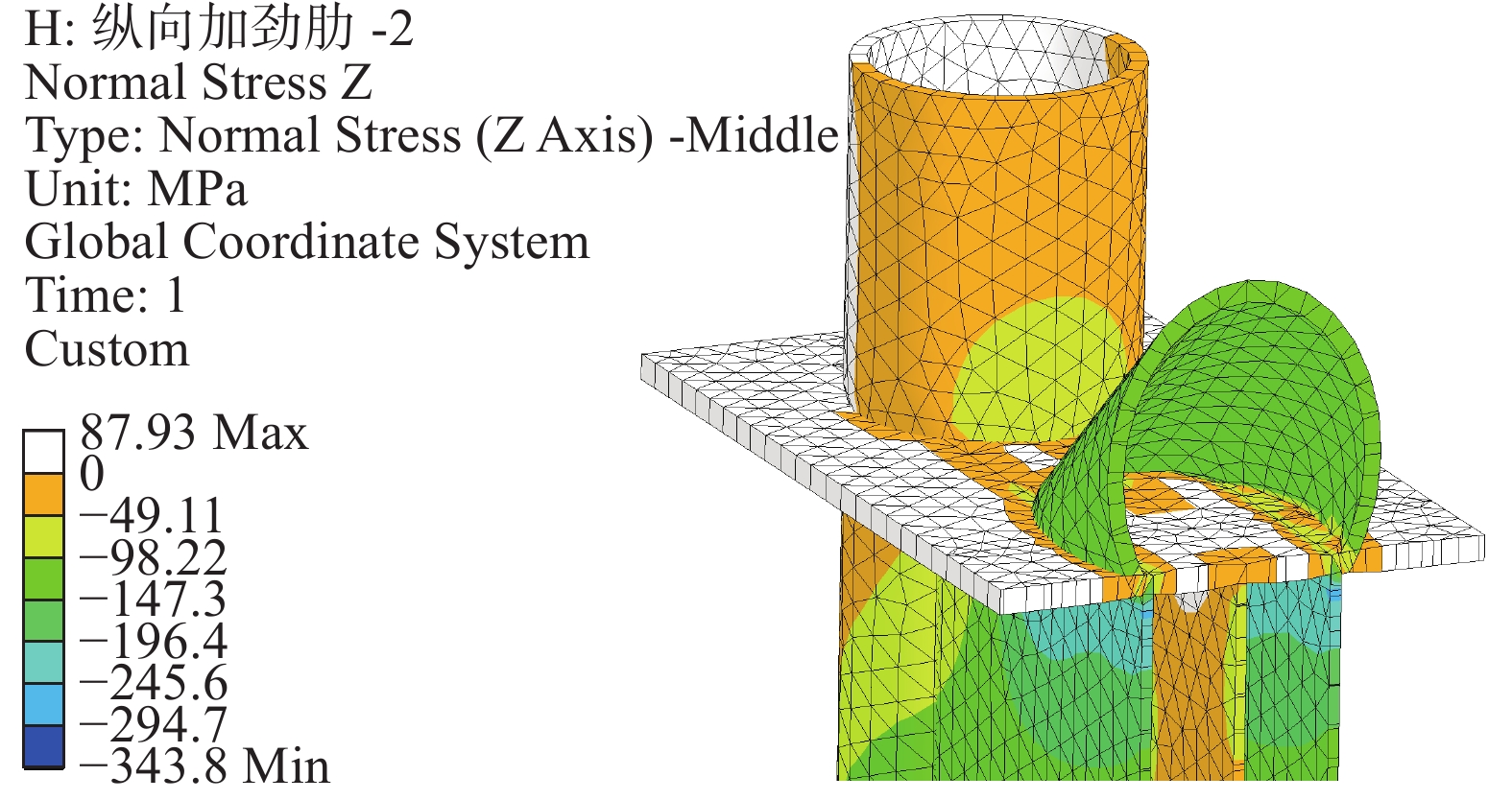
      图11给出了节点剖面的竖向应力云图。由图可知,腹板顶部的竖向应力较小;斜撑轮廓与纵向加劲肋之间的翼缘板承受斜撑的剪力;剪力沿翼缘板传递至纵向加劲肋,使纵向加劲肋承受较高的竖向压力。

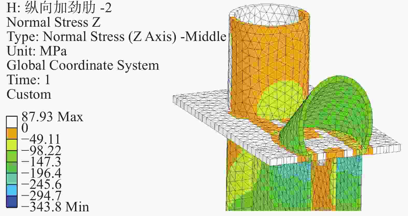
      Figure 11.  Vertical stress contour of joint under axial loading condition
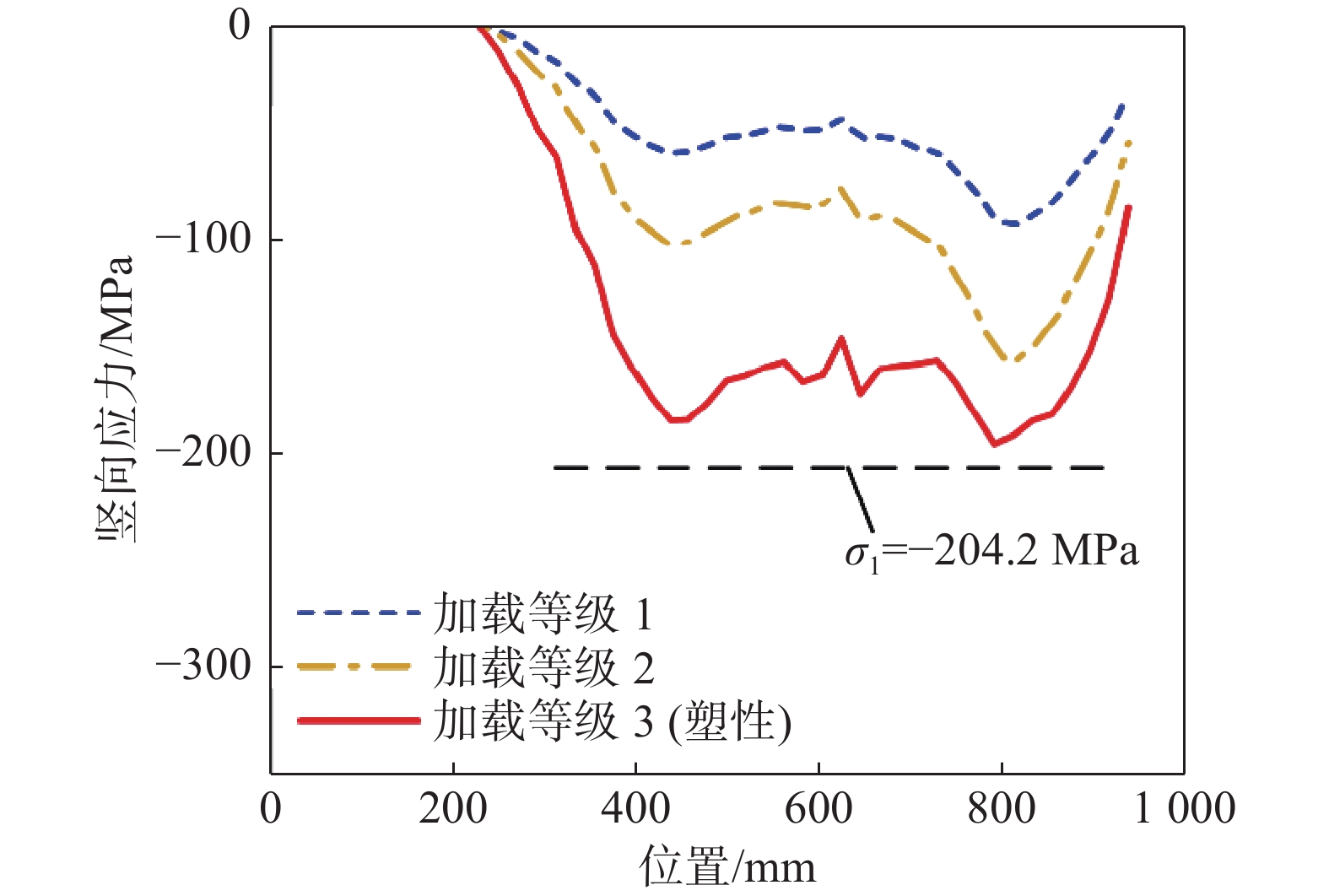
      图12可知,面外转角工况中加劲肋在两个集中力作用点应力较高,而两作用点之间依然保持较高应力水平。简化计算方法给出的应力σ1绝对值高于有限元分析的应力值,表明简化计算方法是偏于安全的。

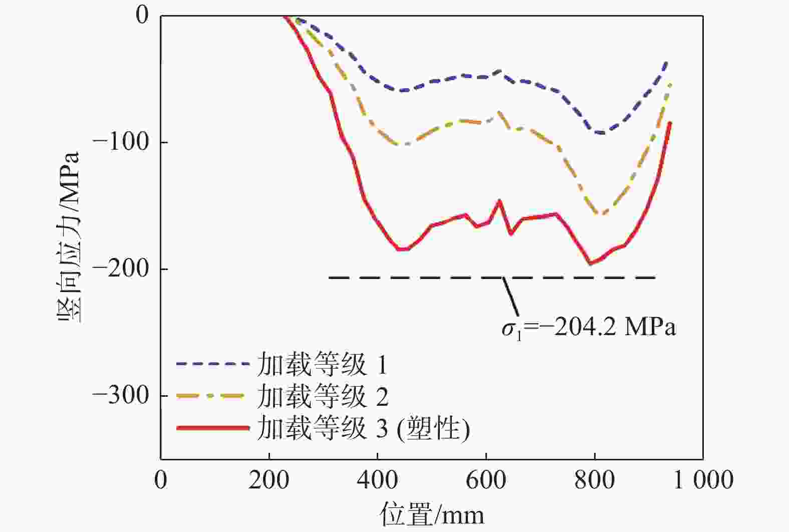
      Figure 12.  Vertical stress distribution at the top of longitudinal stiffener under out-of-plane rotation loading condition
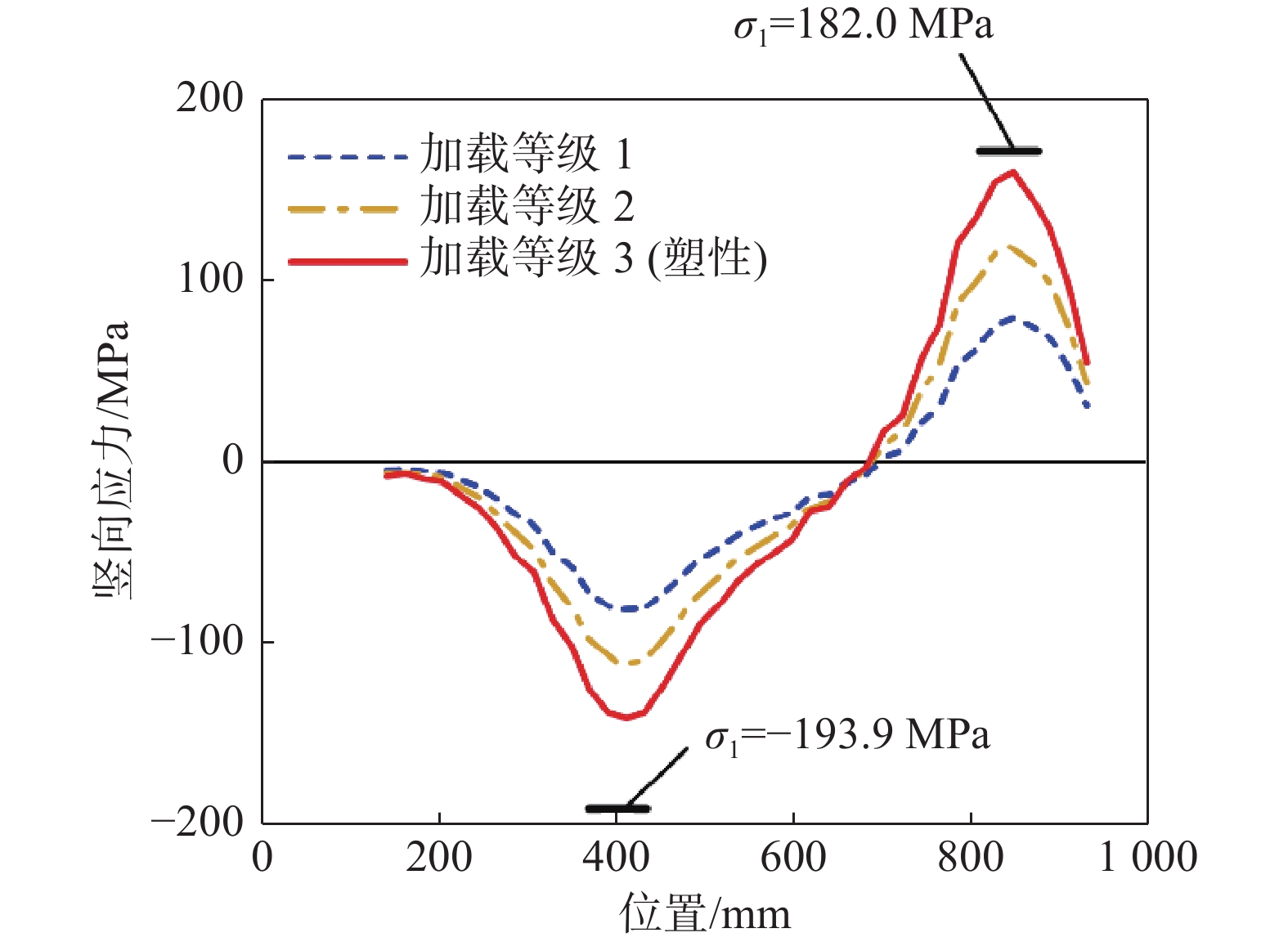
      图13可知,面内转角工况中应力随位置的变化近似满足线性关系,可见纵向加劲肋的变形近似满足平截面假定。简化计算方法给出的应力σ1绝对值高于有限元结果,表明简化计算方法是偏安全的。

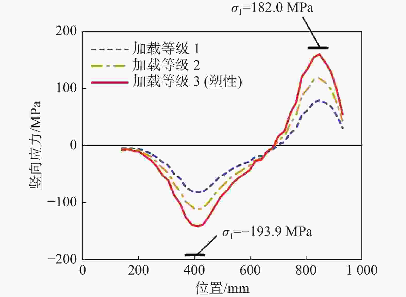
      Figure 13.  Vertical stress distribution at the top of longitudinal stiffener under in-plane rotation loading condition

      对于真实荷载工况,图14表明,简化计算方法给出的应力绝对值高于有限元结果,是偏安全的。

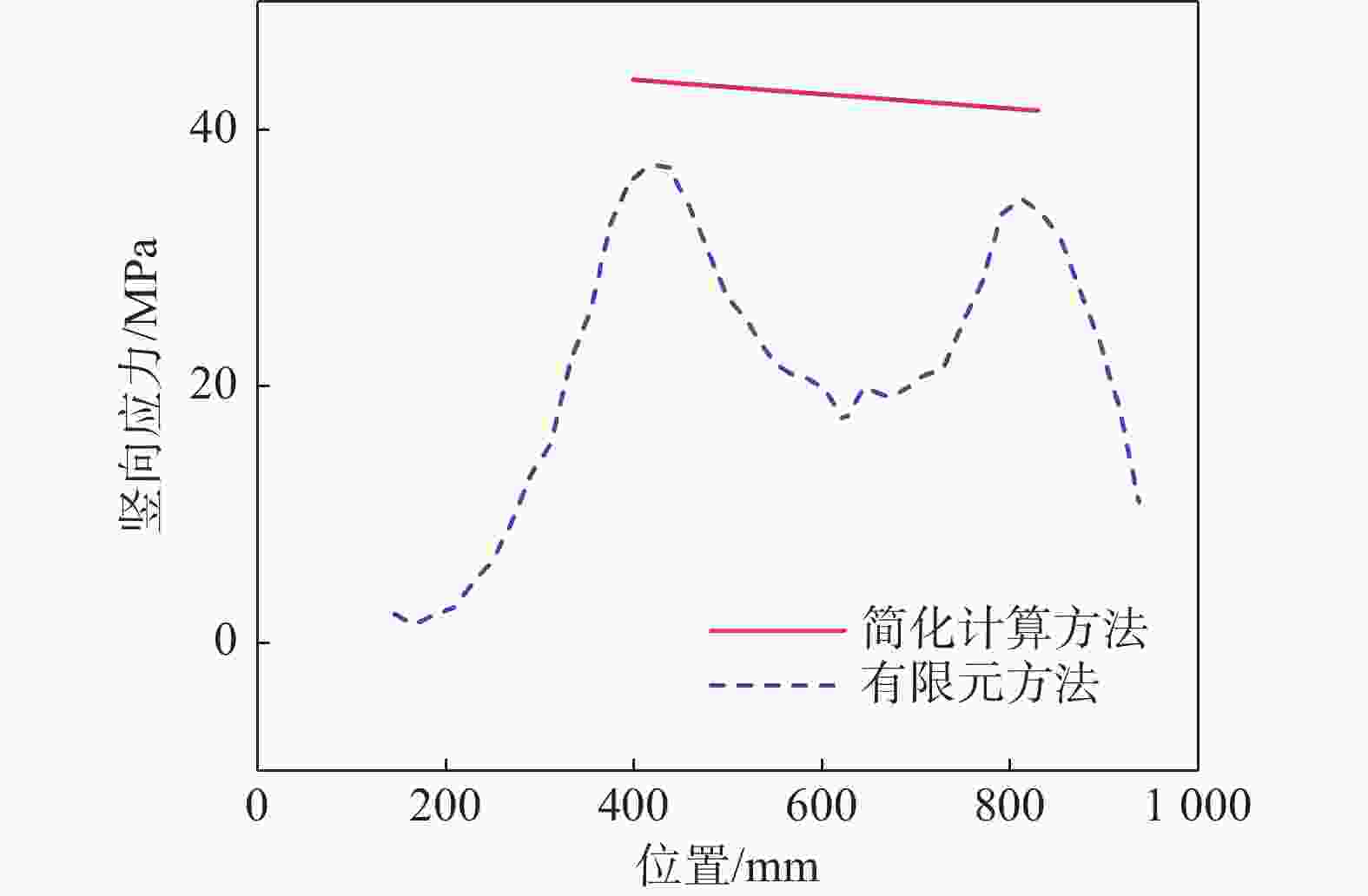
      Figure 14.  Vertical stress distribution at the top of longitudinal stiffener under true loading condition

      综上所述,所提出的简化计算方法与有限元模拟的节点实际受力模式相符,且所得结果偏于安全,能对加劲肋方案进行快速校核。

    • 本文选取海上升压站上部组块节点的简化模型,采用有限元软件对5种加劲肋加强方案的破坏形式进行研究,得出优选方案。针对纵向加劲肋方案进一步优化,提出校核的简化计算方法,并通过有限元分析验证。主要结论如下:

      1)无加强的圆管-工字钢节点无法满足“强节点弱构件”的设计要求,采取加劲肋等加强措施是必要的。

      2)纵向加劲肋方案能满足承载力要求,且用钢量较为经济。纵向加劲肋对于梁腹板受剪承载力至关重要,而横向加劲肋无法提高受剪承载力。

      3)对于纵向加劲肋方案,所提出的简化计算方法给出的结果偏于安全,该方法能对加劲肋方案进行快速校核。

      4)当所设置的纵向加劲肋参数不满足承载力要求时,可增大加劲肋厚度或增设次级横向加劲肋。

Reference (20)

Catalog

    /

    DownLoad:  Full-Size Img  PowerPoint
    Return
    Return