• Peer Review
  • Non-profit
  • Global Open Access
  • Green Channel for Rising Stars
Volume 8 Issue 1
Mar.  2021
Turn off MathJax
Article Contents

MENG Hao,TIAN Liang.Real-time Compensation Strategy for Positioning Accuracy of Electric Actuator[J].Southern Energy Construction,2021,08(01):80-86. doi:  10.16516/j.gedi.issn2095-8676.2021.01.012
Citation: MENG Hao,TIAN Liang.Real-time Compensation Strategy for Positioning Accuracy of Electric Actuator[J].Southern Energy Construction,2021,08(01):80-86. doi:  10.16516/j.gedi.issn2095-8676.2021.01.012

Real-time Compensation Strategy for Positioning Accuracy of Electric Actuator

doi: 10.16516/j.gedi.issn2095-8676.2021.01.012
  • Received Date: 2020-08-06
  • Rev Recd Date: 2020-09-11
  • Publish Date: 2021-03-25
  •   Introduction  In order to reduce the influence of the positioning accuracy of the electric actuator by the change of its internal parameters, and to reduce the maintenance frequency of the electric actuator.  Method  After the model of the electric actuator was improved, the influence factors of the steady-state error were obtained through simulation experiments. The compensation loop was further added to reduce the steady-state error. The parameters of the compensation loop were obtained by utilizing the BP neural network algorithm.  Result  The simulation result shows that the steady-state error of the electric actuator is related to the width of the dead zone of the controller, the backlash width of the reducer and the sign of the input signal. After adding the compensation circuit, the absolute value of the steady-state error can be guaranteed to fluctuate within 0.1% when the controller dead zone width and reducer backlash width change.  Conclusion  It solves the contradiction between the positioning accuracy and stability of electric actuator, and the problem of positioning accuracy being reduced due to the wear of reducer.
  • [1] 徐一森. 工业控制中电动调节阀开度控制特性研究 [D]. 成都:西南石油大学,2016.

    XUY S. Research on the control characteristics of the electric control valve opening in industrial control [D]. Chengdu:Southwest Petroleum University,2016.
    [2] 艾昌文,曹良坤. 电动阀门高灵敏度控制技术研究及其应用[J]. 自动化仪表,2014,35(11):80-82+86.

    AIC W,CAOL K. Research and application of high-sensitivity control technology for electric valves [J]. Automation Instrumentation,2014,35(11):80-82+86.
    [3] 赵全保. BP神经网络在电动执行器控制中的应用 [J]. 华北科技学院学报,2018,15(3):93-97.

    ZHAOQ B. The application of BP neural network in the control of electric actuators [J]. Journal of North China Institute of Science and Technology,2018,15(3):93-97.
    [4] 徐艳超. 基于调速执行机构的一种高精度阀门控制方法实现 [J]. 电工技术,2019(12):17-18+21.

    XUY C. Implementation of a high-precision valve control method based on speed-regulating actuators [J]. Electrical Engineering Technology,2019(12):17-18+21.
    [5] 马艳玲. 含齿隙环节伺服系统的补偿控制 [D]. 西安:西安电子科技大学,2008.

    MAY L. Compensation control of servo system with backlash link [D]. Xi'an:Xidian University,2008.
    [6] 苏亚洲. 高精度电动执行机构的设计研究 [D]. 西安:陕西科技大学,2014.

    SUY Z. Design and research of high-precision electric actuator [D]. Xi’an:Shanxi University of Science and Technology,2014.
    [7] 许海明,何光辉. 电动执行器的行程位置检测 [J]. 仪表技术,2019(2):44-46.

    XUH M,HEG H. The stroke position detection of electric actuators [J]. Instrument Technology,2019(2):44-46.
    [8] 王海荣. 电动执行机构的智能控制研究 [D]. 广州:华南理工大学,2011.

    WangH R. Research on intelligent control of electric actuators [D]. Guangzhou:South China University of Technology,2011.
    [9] 谢志伟. 基于齿隙效应补偿的机电传动系统高性能控制方法研究 [D]. 南京:南京理工大学,2018.

    XIEZ W. Research on high performance control method of electromechanical transmission system based on backlash effect compensation [D]. Nanjing:Nanjing University of Science and Technology,2018.
    [10] 孙辉,章立新,杨其国,等. 基于GA-BP神经网络的S-CO2折射率及密度预测 [J]. 热力发电,2020(49):1-6.

    SUNH,ZHANGL X,YANGQ G,et al. S-CO2 refractive index and density prediction based on GA-BP neural network [J]. Thermal Power Generation,2020(49):1-6.
    [11] 欧卫海. 液偶调速电动给水泵节能改造方案解析—行星齿轮变矩调速器与变频器方案对比 [J]. 南方能源建设,2016,3(增刊1):22-26.

    OU W H. Analysis of the energy-saving transformation plan of the liquid-coupled speed-regulating electric feedwater pump—the comparison between the planetary gear torque converter and the inverter plan [J]. Southern Energy Construction,2016,3(Supp.1):22-26.
    [12] WANGY,DENGX,SUNP. A kind of electric actuator controller solving the problem of motor concussion [C]//Anon.2018 IEEE International Conference on Mechatronics and Automation(ICMA),Changchun,China,August 5-8,2018. Changchun:IEEE,2018:1015-1019.
  • 通讯作者: 陈斌, bchen63@163.com
    • 1. 

      沈阳化工大学材料科学与工程学院 沈阳 110142

    1. 本站搜索
    2. 百度学术搜索
    3. 万方数据库搜索
    4. CNKI搜索

Figures(11)  / Tables(2)

Article Metrics

Article views(320) PDF downloads(22) Cited by()

Related

Real-time Compensation Strategy for Positioning Accuracy of Electric Actuator

doi: 10.16516/j.gedi.issn2095-8676.2021.01.012

Abstract:   Introduction  In order to reduce the influence of the positioning accuracy of the electric actuator by the change of its internal parameters, and to reduce the maintenance frequency of the electric actuator.  Method  After the model of the electric actuator was improved, the influence factors of the steady-state error were obtained through simulation experiments. The compensation loop was further added to reduce the steady-state error. The parameters of the compensation loop were obtained by utilizing the BP neural network algorithm.  Result  The simulation result shows that the steady-state error of the electric actuator is related to the width of the dead zone of the controller, the backlash width of the reducer and the sign of the input signal. After adding the compensation circuit, the absolute value of the steady-state error can be guaranteed to fluctuate within 0.1% when the controller dead zone width and reducer backlash width change.  Conclusion  It solves the contradiction between the positioning accuracy and stability of electric actuator, and the problem of positioning accuracy being reduced due to the wear of reducer.

MENG Hao,TIAN Liang.Real-time Compensation Strategy for Positioning Accuracy of Electric Actuator[J].Southern Energy Construction,2021,08(01):80-86. doi:  10.16516/j.gedi.issn2095-8676.2021.01.012
Citation: MENG Hao,TIAN Liang.Real-time Compensation Strategy for Positioning Accuracy of Electric Actuator[J].Southern Energy Construction,2021,08(01):80-86. doi:  10.16516/j.gedi.issn2095-8676.2021.01.012
  • 电动执行机构广泛应用于电力、冶金、石油、化工、轻工等行业的生产过程控制系统,火电厂中的电动调节阀和风机的风门挡板都属于电动执行机构,被大量用于蒸汽温度控制、给水控制、燃烧控制、负荷控制等环节,一座拥有两台300 MW机组的中型火电厂需要400~500台数量的电动调节阀才能满足控制需求1。定位精度会影响控制系统的控制品质,是电动执行机构的一个重要性能指标。然而由于风电的大规模并网,火电机组频繁的变动负荷增加了电动执行机构的动作频率,使得电动执行机构的磨损速度加快从而导致定位精度下降。为了不会对控制品质产生较大影响需要愈加频繁的对电动执行机构进行维修工作,对于关键部位的电动执行机构甚至需要停机维修,这样一来会降低火电厂的经济效益。因此,若能根据电动执行机构内部的参数对其定位精度进行实时补偿,减小定位精度的波动范围,将对提高热工控制系统的控制品质以及火电厂的经济效益具有重要意义。

    电动执行机构主要由控制器、电动机和减速器三部分组成,关于电动执行机构定位精度的研究,目前相关文献大部分都未涉及到参数变化时的情况。艾昌文通过误差信号的大小确定电动机的转动时间2,赵全宝使用人工神经网络预估电动机的启停位置3,徐艳超通过优化电动机的速度曲线实现精准启停4,这三篇文献提到的方法是通过降低电动机惯性憜走的位移量,从而减小控制器的死区宽度使得定位精度提高,但是以上三篇文献未考虑减小控制器死区宽度后会降低系统的稳定性,容易使得输出信号在减速器齿隙宽度因磨损而增大时产生等幅振荡。马艳玲通过反步积分法设计了自适应控制器降低齿隙非线性的影响5,但是未考虑齿隙宽度发生变化的情况。苏亚洲设计了一种反向机械间隙软件补偿算法补偿齿隙特性的影响6,但是未考虑控制器死区特性的影响。

    本文通过对电动执行机构特性的分析,在原有电动执行机构数学模型的基础上修改了减速器的数学模型,通过特性仿真试验确定了稳态误差的影响因素,然后通过添加补偿回路来减小稳态误差,补偿回路的参数使用BP神经网络算法离线求得,最后通过仿真试验评判该补偿方案的性能。

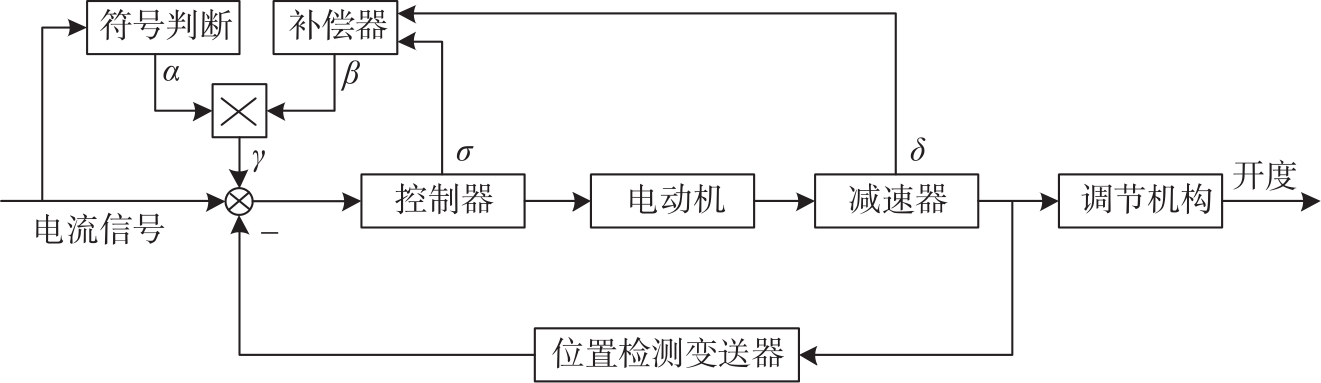
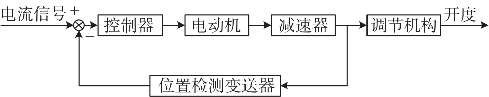
  • 电动执行机构的结构如图1所示。来自上位机中的4 ~20 mA的电流信号在与位置反馈信号做差后将偏差信号送入控制器,控制器输出开关量信号控制电动机旋转,经减速器减速后带动调节机构运动,从而改变执行机构的开度。此外,减速器会带动绝对绝对编码器转动,位置检测变送器通过绝对编码器获得开度信号,经变送后送入控制器7

    Figure 1.  Electric actuator structure

  • 理想状态下电动机可以用积分环节描述,减速器可以用比例环节描述。然而实际的电动机含有惯性特性,在控制器的输出信号改变后,电动机还会朝着原来的方向继续转动一段行程,这种特性被称为电机的惯性憜走。此外,减速器中传动部件间的齿隙非线性特性无法彻底消除。电动机的惯性憜走与传动机构的齿隙特性会使得输出信号产生等幅振荡,控制器也会不断输出变化的信号使电动机做正反转交替运动。这样会消耗能量、磨损减速器,甚至烧坏电动机,大大降低了电动执行机构的使用寿命。为了避免输出信号产生等幅振荡,需要在控制器中设置一定宽度的死区,死区的宽度可以人为进行调节,当误差的绝对值小于或等于死区宽度时,控制器不再输出使电动机转动的信号。这样做虽然可以提高执行机构的稳定性,但是死区特性的存在降低了定位精度,使输出的开度信号产生了稳态误差。

    根据上述对电动执行机构特性的分析可以得到如图2所示的数学模型。关于控制器和电动机的结构,文献[8]已经做了相关研究,故本文不进行重点研究,由于该文献将减速器视为比例环节,忽略了齿隙特性的影响,因此本文对减速器的数学模型进行了修改。图2中,带死区的继电器模块表示控制器,σ为死区的宽度。电动机的传递函数根据文献[8]的研究得到。根据文献[5],[9]的研究,齿隙非线性主要可以用迟滞模型、死区模型及“振-冲”模型三种模型来描述,具体使用何种模型则根据齿隙非线性在系统中的位置及其他元件的特性来确定。减速器位于电动执行机构的输出端,而且调节机构含有一定的阻尼特性,因此本文使用迟滞模型来描述减速器的齿隙特性10-11δ为减速器齿隙宽度。位置检测变送器的增益为0.125 mA/mm。开度变化量与减速器输出端位移的比例系数为0.781 25%/mm。输出信号ct)表示执行机构的开度。

    Figure 2.  Mathematical Model of Electric actuator

  • 根据电动执行机构的数学模型搭建仿真模型对其特性进行分析。电动执行机构中减速器的齿隙宽度δ会随着减速器的磨损而增大,而控制器死区宽度σ需要根据输出特性人为的进行调节。电动机的惯性时间常数T与其机电特性有关,可以视为定值。因此,本文主要研究δσ对输出特性的影响。以σδ为变量进行仿真,参数取值如表1所示,其中σ等间隔取16个值,δ等间隔取8个值,其他固定参数取值如图2所示。

    参数名称最小值间隔最大值
    死区宽度σ/mA0.020.020.32
    齿隙宽度δ/mm0.50.54

    Table 1.  δ and σ parameter values

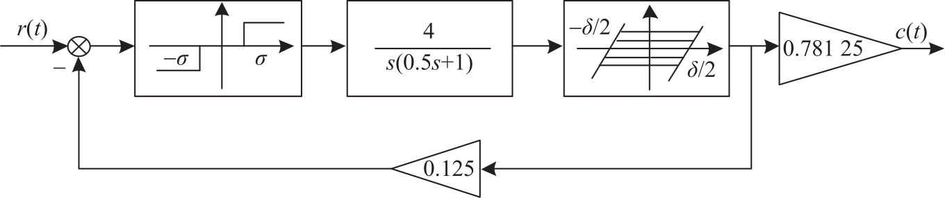
  • 系统的单位阶跃响应曲线可以分为四类。在δ=1 mm时,通过改变σ可以得到这四种类型的阶跃响应曲线,如图3所示。

    Figure 3.  Step response curve

    图3(a)为σ=0.08时,阶跃响应曲线出现等幅振荡特性,系统不稳定。图3(b)为σ=0.12时,阶跃响应曲线经过一个波峰之后进入稳态,稳态误差ess(∞)<0。图3(c)为σ=0.16时,阶跃响应曲线无超调量,直接进入稳态,且ess(∞)>0。图3(d)为σ=0.3时阶跃响应曲线无超调量,但ess(∞)<0。若σ继续增大,ess(∞)会持续增大,直至σrt)后,ct)=0,ess(∞)不再变化。

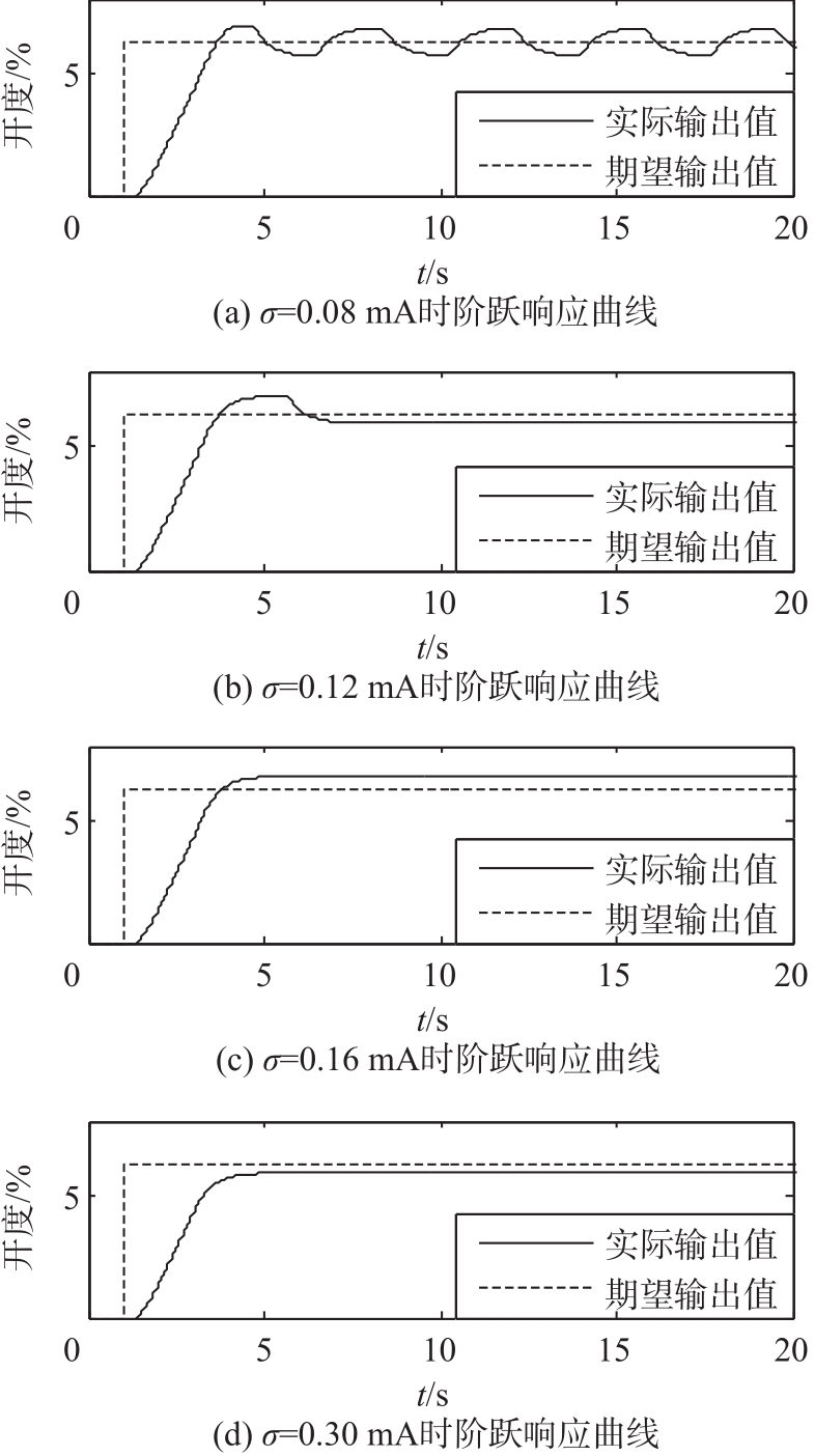
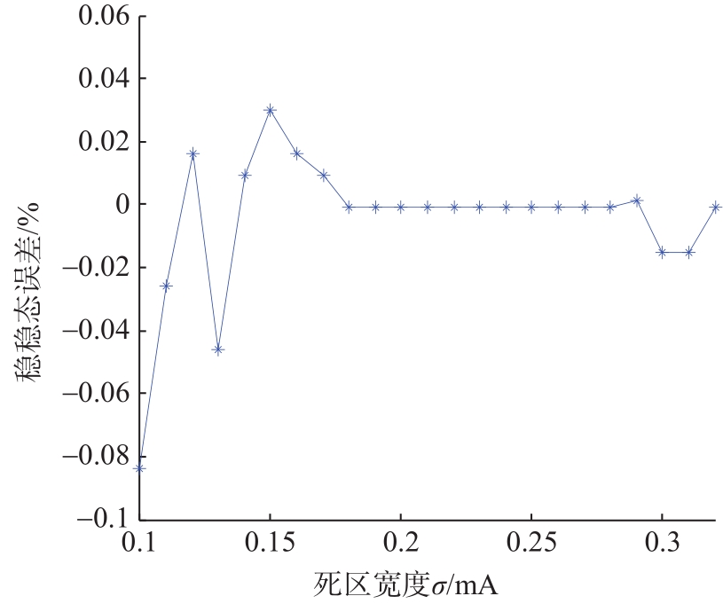
    在阶跃响应曲线无等幅振荡时,稳态误差和死区宽度σ的关系如图4所示,由图4可知,死区宽度在0.1~0.32 mA的范围内变化时,稳态误差在 -0.8%~0.6%的范围内波动。

    Figure 4.  The relationship between dead zone width and steady state error

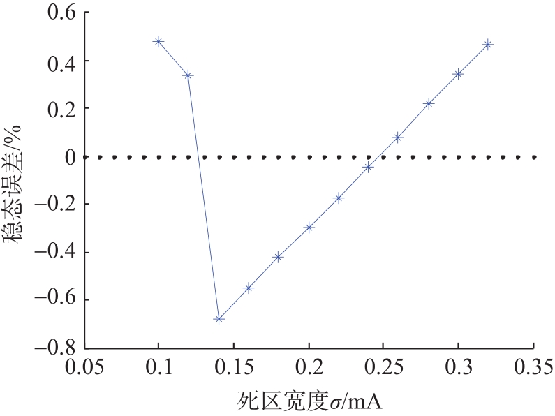
    根据仿真结果可以得到不同δ下使系统稳定的最小死区宽度σmin,如图6所示。由图5可知,δ增大时σmin有可能增大。

    Figure 5.  The relationship between backlash width and minimum dead zone width

    Figure 6.  Schematic diagram of compensation scheme

    通过对σδ不变的系统施加幅值不同但符号为正的阶跃信号,系统稳态误差的波动范围不超过±0.01%,相较于σδ对稳态误差的影响,可以认为稳态误差与阶跃信号幅值的绝对值大小无关。

    通过对σδ不变的系统输入幅值互为相反数的阶跃信号,系统的阶跃响应曲线ct)关于ct)=0对称,且稳态误差互为相反数。

    综上所述,通过对仿真结果的分析,可以得到如下结论:

    1)减速器齿隙宽度增大时会使原本稳定的系统产生等幅振荡,此时可以通过增大控制器死区宽度消除等幅振荡,但死区宽度过大会使得稳态误差过大。

    2)当系统稳定时,稳态误差与控制器死区宽度和减速器齿隙宽度有关,与阶跃信号幅值的绝对值大小无关。幅值互为相反数的阶跃信号造成的稳态误差互为相反数。

  • 本文的设计思路是为电动执行机构添加补偿回路来对定位精度进行实时补偿。根据上一节得出的结论,系统的稳态误差ess(∞)与死区宽度σ和齿隙宽度δ有关,而互为相反数的阶跃信号会使ess(∞)互为相反数,因此本文设计了如图6所示的补偿方案。补偿器根据σδ确定当阶跃信号幅值为正时补偿值的大小β,当最近一次输入正向阶跃信号(反向阶跃信号)时,符号判断模块的输出值α=1(α=-1)。最后再将符号判断模块的输出值α与补偿器的输出值β相乘得到补偿回路的输出值γ

  • 补偿器的参数使用BP神经网络算法求取。补偿器的作用是根据控制器死区宽度σ和减速器齿隙宽度δ确定补偿值的大小β。人工神经网络是一种以人脑基本特性为基础的控制方法,而BP神经网络由于其强大的非线性映射能力和柔性网络结构近年来常被用于处理非线性问题12,是目前应用最多的神经网络模型之一。因此本文用BP神经网络算法建立了以σ和δ为输入变量,β为输出变量的神经网络模型。神经网路输入层节点数为2,隐含层节点数为5,输出层节点数为1,激励函数取Sigmoid函数,函数形式为:

    fx=11+e-x ((1))

    神经网络的训练数据通过仿真得到。σδ取值如表1所示,若仿真结果未出现等幅振荡,记录下此时σδ的取值,并利用以下公式得到使稳态误差为零时期望补偿值βe大小,得到一组训练数据。

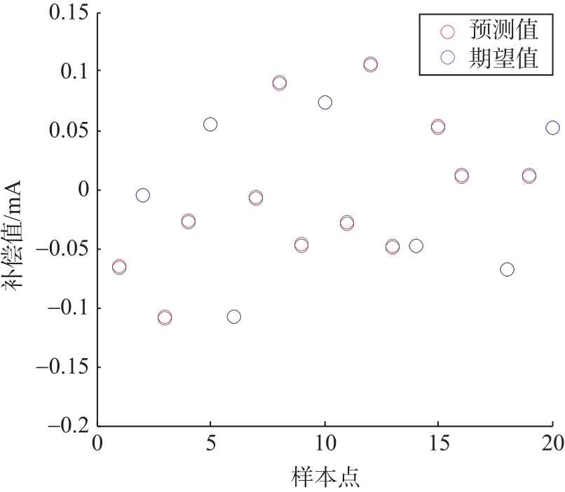
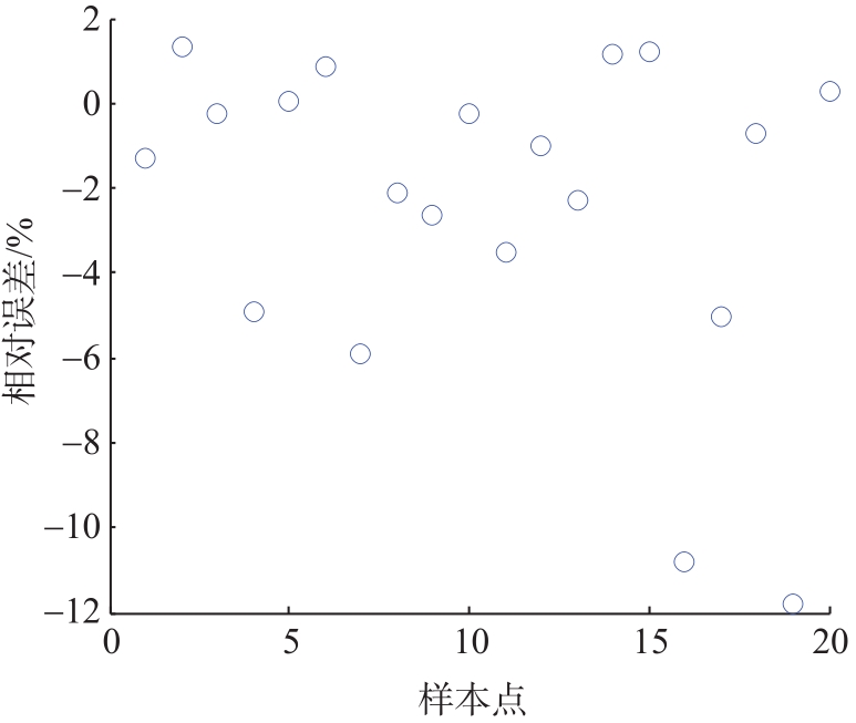
    βe=-ess(∞)*0.125/0.781 25 ((2))

    使用上述方法在128个仿真结果中最终得到91组训练数据。随机选择其中的71组数据对BP神经网络进行训练,部分训练数据如表2所示。使用另外20组未参与训练的数据对训练得到的模型进行测试,测试结果如图7所示,测试数据的误差如图8所示。

    序号死区宽度σ/mA齿隙宽度δ/mm期望补偿值βe/mA
    10.10.50.040 4
    20.120.50.018 8
    30.140.5-0.106 5
    700.2840.032 2
    710.3240.072 2

    Table 2.  Training data (partial)

    Figure 7.  BP neural network test results

    Figure 8.  Relative error of test data

    根据图9可知,20组测试数据的相对误差绝对值小于12%,且有90%的数据的相对误差绝对值小于6%,因此该模型有较好的泛化能力。

    Figure 9.  Step response curve of uncompensated system and compensated system

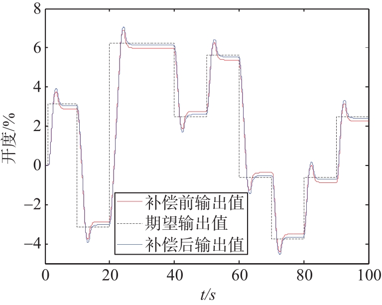
  • 设置控制器死区宽度σ=0.1 mA,减速器齿隙宽度δ=0.5 mm。图9为补偿前后系统的阶跃响应曲线。

    通过图9可知,对于不同幅值的阶跃输入信号,补偿之后系统的稳态误差比未补偿系统的稳态误差小,通过计算得到经过补偿能够使系统稳态误差的绝对值降低至0.1%以内。

    图10δ=1 mm时,σ与稳态误差的关系曲线,通过比较图4图10可知,补偿后系统的稳态误差波动范围变小,稳态误差的绝对值稳定在0.1%的范围内。

    Figure 10.  The relationship between the steady-state error and dead zone width after compensation
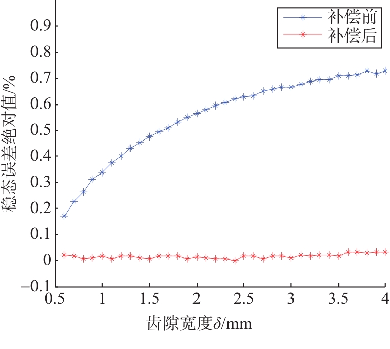
    图11σ=0.12 mA时,保证系统稳定的前提下补偿前后稳态误差的绝对值与δ的关系。根据图11可知,补偿后系统稳态误差的绝对值不再与δ呈正相关,始终在小于0.1%的范围内小幅波动。

    Figure 11.  The relationship between absolute value of steady-state error and backlash width

  • 针对电动执行机构的定位精度会因内部参数的变化而产生大幅波动的问题,提出了通过添加补偿回路来稳定定位精度,补偿回路的输出值与控制器死区宽度、减速器齿隙宽度和输入信号符号有关,补偿回路的参数使用BP神经网络算法确定。仿真结果表明:

    1)添加补偿回路后,定位精度不再因控制器死区宽度的增大而大幅降低,解决了电动执行机构定位精度与稳定性之间的矛盾。

    2)该补偿方案能够在减速器齿隙宽度发生变化时减小定位精度的波动范围,解决了电动执行机构的定位精度因减速器磨损而降低的问题。

Reference (12)

Catalog

    /

    DownLoad:  Full-Size Img  PowerPoint
    Return
    Return