• Peer Review
  • Non-profit
  • Global Open Access
  • Green Channel for Rising Stars
Volume 9 Issue 4
Dec.  2022
Turn off MathJax
Article Contents

LIU Senlin, ZHOU Guangbing, WANG Xiao, YAN Xiao. Research on Reliability Probability of SRSS Method for Multi-Point Displacement of Foundation of H-Class Gas Turbine in High Position[J]. SOUTHERN ENERGY CONSTRUCTION, 2022, 9(4): 159-166. doi: 10.16516/j.gedi.issn2095-8676.2022.04.020
Citation: LIU Senlin, ZHOU Guangbing, WANG Xiao, YAN Xiao. Research on Reliability Probability of SRSS Method for Multi-Point Displacement of Foundation of H-Class Gas Turbine in High Position[J]. SOUTHERN ENERGY CONSTRUCTION, 2022, 9(4): 159-166. doi: 10.16516/j.gedi.issn2095-8676.2022.04.020

Research on Reliability Probability of SRSS Method for Multi-Point Displacement of Foundation of H-Class Gas Turbine in High Position

doi: 10.16516/j.gedi.issn2095-8676.2022.04.020
  • Received Date: 2021-07-23
  • Rev Recd Date: 2021-12-15
  • Available Online: 2022-12-25
  • Publish Date: 2022-12-23
  •   Introduction  The foundation of a large H-class gas turbine usually has multiple disturbing forces, and the vibration displacement of the mass points is obtained by the square root of the sum of the squares (SRSS) method, but the vibration displacement obtained by the SRSS method is not the maximum possible displacement. The research aims to analyze all possible vibration displacements and study the reliability probability of the SRSS method.   Method  A three-dimensional finite element model was established for the foundation of a H-class gas turbine in high position, the unidirectional disturbing forces separately applied on mass points were analyzed, and the vibration displacement of the mass points was calculated by the SRSS method. It was proposed to apply the bidirectional disturbing forces on the mass points separately. Considering the uncertainty of angle between the disturbing forces at the mass points, the linear superposition method was used to calculate all possible vibration displacements and analyze their statistical probability distribution.   Result  The combined value of the lateral vibration displacement of mass point 10 of the H-class gas turbine at 40.75 Hz by the SRSS method is 16.40 μm, and the maximum possible lateral vibration displacement value is 24.18 μm. The reliability probability of the SRSS method is about 50%.   Conclusion  The multi-point vibration displacement value obtained based on the SRSS method is not the maximum value, and the method has a certain reliability probability. For particularly sensitive or important dynamic foundation analysis, the reliability probability of the method should be controlled, and it can be improved by increasing the margin.
  • [1] 王世宏. “十四五”能源规划应提高天然气发电比重 [N]. 中国能源报, 2020-06-15(4).

    WANG S H. The "14th Five-Year" energy plan should increase the proportion of natural gas power generation [N]. China Energy News, 2020-06-15(4).
    [2] 陈路遥, 谈臻, 仇俊. 低位布置燃机基础考虑桩基动刚度影响分析 [J]. 电力勘测设计, 2020(6): 32-37. DOI:  10.13500/j.dlkcsj.issn1671-9913.2020.06.007.

    CHEN L Y, TAN Z, QIU J. Analysis of low arranged gas turbine foundation considering pile dynamic stiffness [J]. Electric Power Survey & Design, 2020(6): 32-37. DOI:  10.13500/j.dlkcsj.issn1671-9913.2020.06.007.
    [3] 龙杨洋. 基于GE机型的落地式燃机基础设计分析研究 [J]. 中国设备工程, 2018(24): 226-227. DOI:  10.3969/j.issn.1671-0711.2018.24.115.

    LONG Y Y. Analysis and research on the basic design of floor-mounted gas turbines based on GE models [J]. China Plant Engineering, 2018(24): 226-227. DOI:  10.3969/j.issn.1671-0711.2018.24.115.
    [4] 刘森林, 王忠, 陈其春, 等. 基于响应面方法的H级燃机基础动力性能研究 [J]. 南方能源建设, 2021, 8(2): 17-24. DOI:  10.16516/j.gedi.issn2095-8676.2021.02.003.

    LIU S L, WANG Z, CHEN Q C, et al. Dynamic characteristics analysis of H-class gas turbines foundation based on response surface methodology [J]. Southern Energy Construction, 2021, 8(2): 17-24. DOI:  10.16516/j.gedi.issn2095-8676.2021.02.003.
    [5] 彭晓帆, 刘同华, 李炳益, 等. 9H级燃机基础动力分析 [J]. 武汉大学学报(工学版), 2018, 51(增刊1): 217-220.

    PENG X F, LIU T H, LI B Y, et al. Dynamic analysis of 9H level gas-turbine-generator foundation [J]. Engineering Journal of Wuhan University, 2018, 51(Supp. 1): 217-220.
    [6] 陈燕, 张保龙, 黄小玲. 三菱9F燃机基础动力特性分析 [J]. 武汉大学学报(工学版), 2018, 51(增刊1): 261-264.

    CHEN Y, ZHANG B L, HUANG X L. Dynamic analysis of foundation structure for MHI's gas-turbine [J]. Engineering Journal of Wuhan University, 2018, 51(Supp. 1): 261-264.
    [7] 杨保硫. 西门子F级燃机基座瞬态动力分析研究 [J]. 能源与环境, 2015, 4(6): 6-8. DOI:  10.3969/j.issn.1672-9064.2015.06.004.

    YANG B L. Research on transient dynamic analysis of siemens F-class gas turbine base [J]. Energy and Environment, 2015, 4(6): 6-8. DOI:  10.3969/j.issn.1672-9064.2015.06.004.
    [8] 吴兰英, 方伟定. GE大块式燃机基座设计分析 [J]. 山西建筑, 2013, 39(8): 51-53. DOI:  10.3969/j.issn.1009-6825.2013.08.029.

    WU L Y, FANG W D. The design analysis on GE bulk type combustion engine base [J]. Shanxi Architecture, 2013, 39(8): 51-53. DOI:  10.3969/j.issn.1009-6825.2013.08.029.
    [9] 黄小玲, 沈涛, 朱祝兵, 等. 结合实例对9E型燃机基础的动扰力和动力特性的探讨 [J]. 特种结构, 2012, 29(6): 68-73,103.

    HUANG X L, SHEN T, ZHU Z B, et al. Study on imbalance force and dynamical property of GE9E gas-turbine set foundation with example [J]. Special Structures, 2012, 29(6): 68-73,103.
    [10] 杨辉. 巴基斯坦某燃机联合循环电厂工程燃气轮发电机基础动力特性数模分析 [D]. 西安: 西安建筑科技大学, 2012. DOI:  10.7666/d.d244590.

    YANG H. Mathematical model analysis of G-T foundation of a certain pakistan combined cycle power plant [D]. Xi'an: Xi'an University of Architecture and Technology, 2012. DOI:  10.7666/d.d244590.
    [11] 中国机械工业集团有限公司. 建筑振动荷载标准: GB/T51228-2017 [S]. 北京: 住房与城乡建设部, 2017.

    SINOMACH. Standard for vibration load of buildings: GB/T51228-2017 [S]. Beijing: Ministry of Housing and Urban-Rural Development of the People's Republic of China, 2013.
    [12] 中国机械工业集团有限公司. 建筑工程容许振动标准: GB 50868-2013 [S]. 北京: 住房和城乡建设部, 国家质量监督检验检疫总局, 2013.

    SINOMACH. Standard for allowable vibration of building engineering: GB 50868-2013 [S]. Beijing: Ministry of Housing and Urban-Rural Development of the People's Republic of China, General Administration of Quality Supervision, Inspection and Quarantine of the People's Republic of China, 2013.
    [13] 王浩, 赵学毅. 燃机基座动力分析 [J]. 武汉大学学报(工学版), 2010, 43(增刊1): 225-226.

    WANG H, ZHAO X Y. Dynamic analysis of foundation bed for gas turbines [J]. Engineering Journal of Wuhan University, 2010, 43(Supp. 1): 225-226.
    [14] 陈文超, 刘超, 方翔, 等. 不平衡量对非线性转子-挤压油膜阻尼器系统临界转速影响的研究 [J]. 装备制造技术, 2021(8): 65-68. DOI:  10.3969/j.issn.1672-545X.2021.08.018.

    CHEN W C, LIU C, FANG X, et al. Research on the influence of unbalance on the critical speed of nonlinear rotor-squeeze film damper system [J]. Equipment Manufacturing Technology, 2021(8): 65-68. DOI:  10.3969/j.issn.1672-545X.2021.08.018.
    [15] 程亮元. 汽轮机高位布置对转子—轴承系统振动特性的影响 [D]. 吉林: 东北电力大学, 2020. DOI: 10.27008/d.cnki.gdbdc.2020.000334.

    CHENG L Y. The influence of the high-position arrangement of the steam turbine on the vibration characteristics of the rotor-bearing system [D]. Jilin: Northeast Electric Power University, 2020. DOI: 10.27008/d.cnki.gdbdc.2020.000334.
    [16] 解梦涛, 董江, 张强波. 基于有限元的转子动力学建模仿真与不平衡响应分析 [J]. 现代机械, 2020(5): 70-73. DOI:  10.13667/j.cnki.52-1046/th.2020.05.017.

    XIE M T, DONG J, ZHANG Q B. Dynamic simulation and unbalance response analysis of the rotor based on finite element method [J]. Modern Machinery, 2020(5): 70-73. DOI:  10.13667/j.cnki.52-1046/th.2020.05.017.
    [17] 何文博, 潘豹, 白杰. 挤压油膜阻尼器转子系统突加不平衡瞬态响应分析 [J]. 燃气涡轮试验与研究, 2020, 33(1): 36-40. DOI:  10.3969/j.issn.1672-2620.2020.01.007.

    HE W B, PAN B, BAI J. Transient response analysis of squeezed film damper rotor system under sudden unbalance load [J]. Gas Turbine Experiment and Research, 2020, 33(1): 36-40. DOI:  10.3969/j.issn.1672-2620.2020.01.007.
  • 通讯作者: 陈斌, bchen63@163.com
    • 1. 

      沈阳化工大学材料科学与工程学院 沈阳 110142

    1. 本站搜索
    2. 百度学术搜索
    3. 万方数据库搜索
    4. CNKI搜索

Figures(6)  / Tables(3)

Article Metrics

Article views(105) PDF downloads(24) Cited by()

Related

Research on Reliability Probability of SRSS Method for Multi-Point Displacement of Foundation of H-Class Gas Turbine in High Position

doi: 10.16516/j.gedi.issn2095-8676.2022.04.020

Abstract:   Introduction  The foundation of a large H-class gas turbine usually has multiple disturbing forces, and the vibration displacement of the mass points is obtained by the square root of the sum of the squares (SRSS) method, but the vibration displacement obtained by the SRSS method is not the maximum possible displacement. The research aims to analyze all possible vibration displacements and study the reliability probability of the SRSS method.   Method  A three-dimensional finite element model was established for the foundation of a H-class gas turbine in high position, the unidirectional disturbing forces separately applied on mass points were analyzed, and the vibration displacement of the mass points was calculated by the SRSS method. It was proposed to apply the bidirectional disturbing forces on the mass points separately. Considering the uncertainty of angle between the disturbing forces at the mass points, the linear superposition method was used to calculate all possible vibration displacements and analyze their statistical probability distribution.   Result  The combined value of the lateral vibration displacement of mass point 10 of the H-class gas turbine at 40.75 Hz by the SRSS method is 16.40 μm, and the maximum possible lateral vibration displacement value is 24.18 μm. The reliability probability of the SRSS method is about 50%.   Conclusion  The multi-point vibration displacement value obtained based on the SRSS method is not the maximum value, and the method has a certain reliability probability. For particularly sensitive or important dynamic foundation analysis, the reliability probability of the method should be controlled, and it can be improved by increasing the margin.

LIU Senlin, ZHOU Guangbing, WANG Xiao, YAN Xiao. Research on Reliability Probability of SRSS Method for Multi-Point Displacement of Foundation of H-Class Gas Turbine in High Position[J]. SOUTHERN ENERGY CONSTRUCTION, 2022, 9(4): 159-166. doi: 10.16516/j.gedi.issn2095-8676.2022.04.020
Citation: LIU Senlin, ZHOU Guangbing, WANG Xiao, YAN Xiao. Research on Reliability Probability of SRSS Method for Multi-Point Displacement of Foundation of H-Class Gas Turbine in High Position[J]. SOUTHERN ENERGY CONSTRUCTION, 2022, 9(4): 159-166. doi: 10.16516/j.gedi.issn2095-8676.2022.04.020
  • 随着“十四五”期间能源规划的提出,推动能源系统低碳转型,提高能源利用率,成为各国能源从业者共同的目标[1]。燃气-蒸汽联合循环发电作为低碳环保、能源梯级利用的典型代表,其供电的联合循环效率可达63.88%,在能源利用效率方面比常规燃煤机组有着明显的优势。燃机常规机组一般采用低位布置[2-3]。目前,粤港澳大湾区正在建设的某项目采用高位布置的H级燃气-蒸汽联合循环机组,该项目采用3台目前世界最先进、净效率最高的9HA.02型燃气轮机,为区域绿色、低碳、循环经济发展起到重要示范作用。

    H级燃机是动力设备,运行中对振动控制要求较高,过大的振动将使燃机损坏,因此保证H级燃机基础良好的动力特性对燃机的平稳运行至关重要[4]。大型H级燃机基础通常具有多个扰力作用,并采用平方和开平方根(Square Root of the Sum of the Squares,SRSS)法求得质点的振动位移[5-7],但SRSS法求得的振动位移并不是可能发生的最大位移,通过采用线性叠加法对H级燃机基础可能出现的振动位移计算并统计分析,获得SRSS法的可靠概率。

    • 某9HA.02型燃气轮机单循环功率可达571 MW左右,燃气轮机机组额定转速为3000 r/min,燃机采用高位布置,汽轮机发电机侧采用框架结构,燃机侧采用墙式结构,运转层标高13.700 m,转子中心标高为14.700 m,基础采用桩基形式,共布置182根$ \mathrm{\varnothing }800 $灌注桩。高位燃机基础平立面布置图见图1

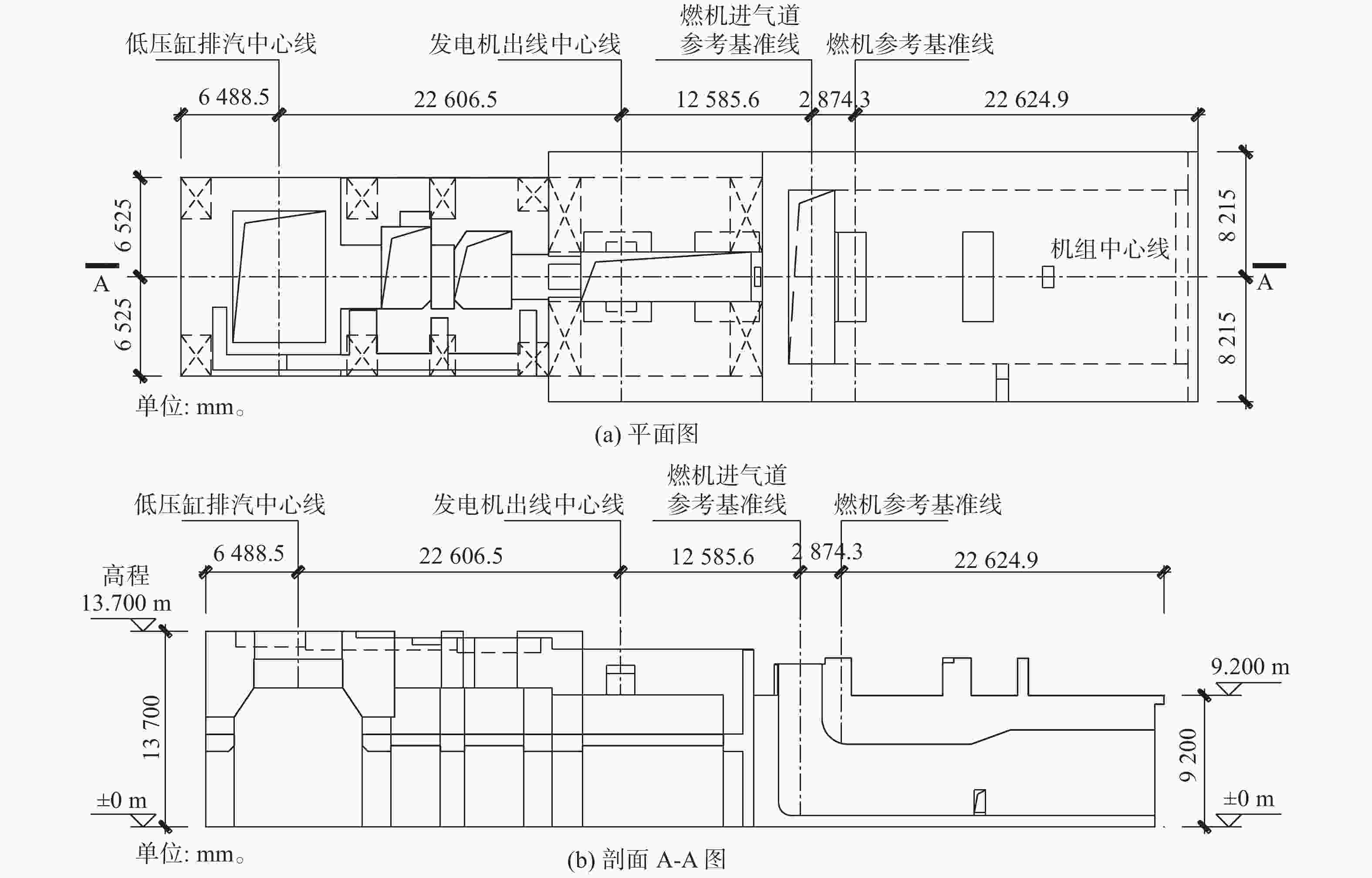
      Figure 1.  Layout of foundation of H-class combined cycle gas-steam turbine generator

    • H级燃机基础受到转子不平衡力作用处于简谐振动状态[8-10]。基础受到的不平衡力和基础本身的响应均呈现出随时间按正弦函数变化的规律。结构动力学的通用方程为:

      $${\boldsymbol{M}}\ddot{{\boldsymbol{x}}}+{\boldsymbol{C}}\dot{{\boldsymbol{x}}}+{\boldsymbol{K}}{\boldsymbol{x}}={\boldsymbol{F}} $$ (1)

      式中,

      M ——质量矩阵;

      C ——阻尼矩阵;

      K ——刚度矩阵;

      F ——载荷矩阵;

      $\ddot{{\boldsymbol{x}}}$ ——结构加速度向量(m/s2);

      $\dot{{\boldsymbol{x}}}$ ——结构速度向量(m/s);

      ${\boldsymbol{x}}$ ——结构位移向量(m)。

      在谐响应分析中,结构的载荷与响应被假定为简谐的:

      $$ {\boldsymbol{F}}=\left({F}_{{\rm{max}}}{e}^{j\psi }\right){e}^{j\omega t} $$ (2)
      $$ {\boldsymbol{x}}=\left({x}_{{\rm{max}}}{e}^{j\varphi }\right){e}^{j\omega t} $$ (3)

      式中:

      $ \omega $ ——激振频率,指加载产生的频率(Hz);

      $ \psi $ ——几个不同相位的载荷同时发生激振时,产生一个力相位变换;

      $ \varphi $ ——如存在阻尼或力的相位变换,产生的一个位移相位变换。

      对于谐响应分析,复数响应${{\boldsymbol{x}}}_{1}$${{\boldsymbol{x}}}_{2}$可从矩阵方程的求解中获得:

      $$ \left(-{\mathrm{{\boldsymbol{{\Omega}}} }}^{2}{\boldsymbol{M}}+j\mathrm{{\boldsymbol{{\Omega}}} }{\boldsymbol{C}}+{\boldsymbol{K}}\right)\left({{\boldsymbol{x}}}_{1}+j{{\boldsymbol{x}}}_{2}\right)={{\boldsymbol{F}}}_{1}+j{{\boldsymbol{F}}}_{2} $$ (4)

      载荷${\boldsymbol{F}}$与响应${\boldsymbol{x}}$虽然有相位的存在,但均按给定的频率$ \omega $作正弦变化。

    • 燃机基础稳态分析时,应优先采用机器制造厂提供的扰力值。当缺乏扰力资料时,根据规范《建筑振动荷载标准》(GB/T 51228-2017)[11]重型燃气轮机作用在基础上的振动荷载宜按下列公式计算:

      $$ {F}_{i}={m}_{i}{G}\frac{{\omega }^{2}}{{\omega }_{0}} $$ (5)

      式中:

      $ {F}_{i} $ ——第i点转速为$ \omega $时的动扰力(N);

      $ {m}_{i} $ ——作用在基础i点上的转子质量(kg);

      G ——衡量转子平衡品质等级的参数(m/s),一般情况下可取$ 6.3\times {10}^{-3} $m/s;

      $ {\omega }_{0} $ ——机器设计额定运转速度时的角速度(rad/s);

      $ \omega $ ——计算振动荷载转速时的角速度(rad/s)。

      多质点动扰力之间可能不同时发生在同一个平面上,而是存在一个角度。此角度由转子本身偏心位置决定,在实际转子运行中各动扰力之间的角度为确定值;但在设计阶段往往不能提前获得各动扰力之间的角度。从概率统计上,假定各动扰力之间存在的任意角度(0°~360°)为等可能事件。此燃机转子平衡品质等级取G6.3,阻尼比6.25%,动扰力及其可能角度见表1

      设备轴承节点转子重/
      kN
      50 Hz动扰力/
      kN
      可能角度/
      (°)
      汽轮机140480.80~360
      243286.40~360
      38416.80~360
      413827.60~360
      5336.60~360
      6336.60~360
      发电机7408.281.60~360
      8408.281.60~360
      燃气轮机9583.6116.70~360
      10497.899.60~360

      Table 1.  Dynamic disturbing forces of foundation of gas-steam turbine

    • 1)SRSS法。一般情况下,多质点分别施加单向扰力(水平或竖向)进行分析,并采用SRSS法计算质点振动位移,计算公式如下:

      $$ {u}_{i{\rm{v}}}=\sqrt{\sum _{k=1}^{m}{{u}_{i{\rm{v}}k}}^{2}} $$ (6)
      $$ {u}_{i{\rm{h}}}=\sqrt{\sum _{k=1}^{m}{{u}_{i{\rm{h}}k}}^{2}} $$ (7)

      式中:

      ${u}_{i{\rm{v}}}$ ——质点i的竖向振动位移(m);

      ${u}_{i{\rm{v}}k}$ ——第k个扰力对质点i产生的竖向振动位移(m);

      ${u}_{i{\rm{h}}}$ ——质点i的水平振动位移(m);

      ${u}_{i{\rm{h}}k}$ ——第k个扰力对质点i产生的水平振动位移(m)。

      2)线性叠加法(Linear Superposition Method,LSM)。由于各质点动扰力之间角度的不确定,又因为谐响应分析扰力和位移都为简谐振动,所以各扰力在某质点产生的振动位移亦可能存在任意角度(0°~360°)的相位差。因此,采用多质点分别施加双向扰力,即每个质点同时施加一定相位相差的水平和竖向动扰力,以模拟动扰力在质点处的旋转作用,并采用线性叠加法(LSM)计算所有可能的振动位移,计算公式如下:

      $$ {{u}}_{i{\rm{v}}-{\rm{LSM}}}=\underset{0\le t\le T}{\mathrm{max}}\left(\sum _{k=1}^{m}{u}_{i{\rm{v}}k}\mathrm{sin}\left(\omega t+{\varphi }_{{\rm{v}}k}\right)\right) $$ (8)
      $$ {{u}}_{i{\rm{h}}-{\rm{LSM}}}=\underset{0\le t\le T}{\mathrm{m}\mathrm{a}\mathrm{x}}\left(\sum _{k=1}^{m}{u}_{i{\rm{h}}k}\mathrm{sin}\left(\omega t+{\varphi }_{{\rm{h}}k}\right)\right) $$ (9)

      式中:

      ${u}_{i{\rm{v}}-{\rm{LSM}}}$——质点i的线性叠加法求得的所有可能竖向振动位移(m);

      $ t $ ——时间(s);

      T ——与$ \omega $对应的周期(s);

      ${\varphi }_{{\rm{v}}k}$ ——第k个扰力对质点i产生的竖向振动位移可能存在的相位角(°);

      ${u}_{i{\rm{h}}-{\rm{LSM}}}$——质点i的线性叠加法求得的所有可能水平振动位移(m);

      ${\varphi }_{{\rm{h}}k}$ ——第k个扰力对质点i产生的水平振动位移可能存在的相位角(°)。

    • H级燃机基础的动力振动控制,根据《建筑工程容许振动标准》(GB 50868-2013)[12],对于重型燃气轮机基础额定转速3000 r/min,在机器额定转速$ \pm 25\mathrm{\%} $范围内扫频分析,基础控制点容许振动位移峰值为20 μm。当机组转速小于额定转速的75%时,其容许振动位移峰值为30 μm。

    • 采用SAP2000软件建立H级单轴联合循环燃气-蒸汽轮发电机基础的三维有限元模型。汽机发电机端的梁柱采用杆单元模拟,燃机端的墙体采用壳单元模拟,以保证模型质量接近真实分布。在燃机转子中心标高处建立转子节点编号1~10,转子中心点与基础顶面采用刚性杆连接,转子质量通过荷载质量源方式输入。桩基采用竖向和两个水平向弹簧单元模拟,根据地勘报告及相关规范计算得到单桩竖向动刚度为${k}_{{\rm{v}}}$=1.66×10⁶ kN/m,单桩水平动刚度${k}_{{\rm{h}}}$=4.18×105 kN/m。混凝土采用C40,密度为25 kg/m3,泊松比为0.2。H级单轴联合循环燃气-蒸汽轮发电机基础有限元模型见图2。其中,X轴为纵向,Y轴为横向,Z轴为竖向。重力加速度g取9.81 m/s2

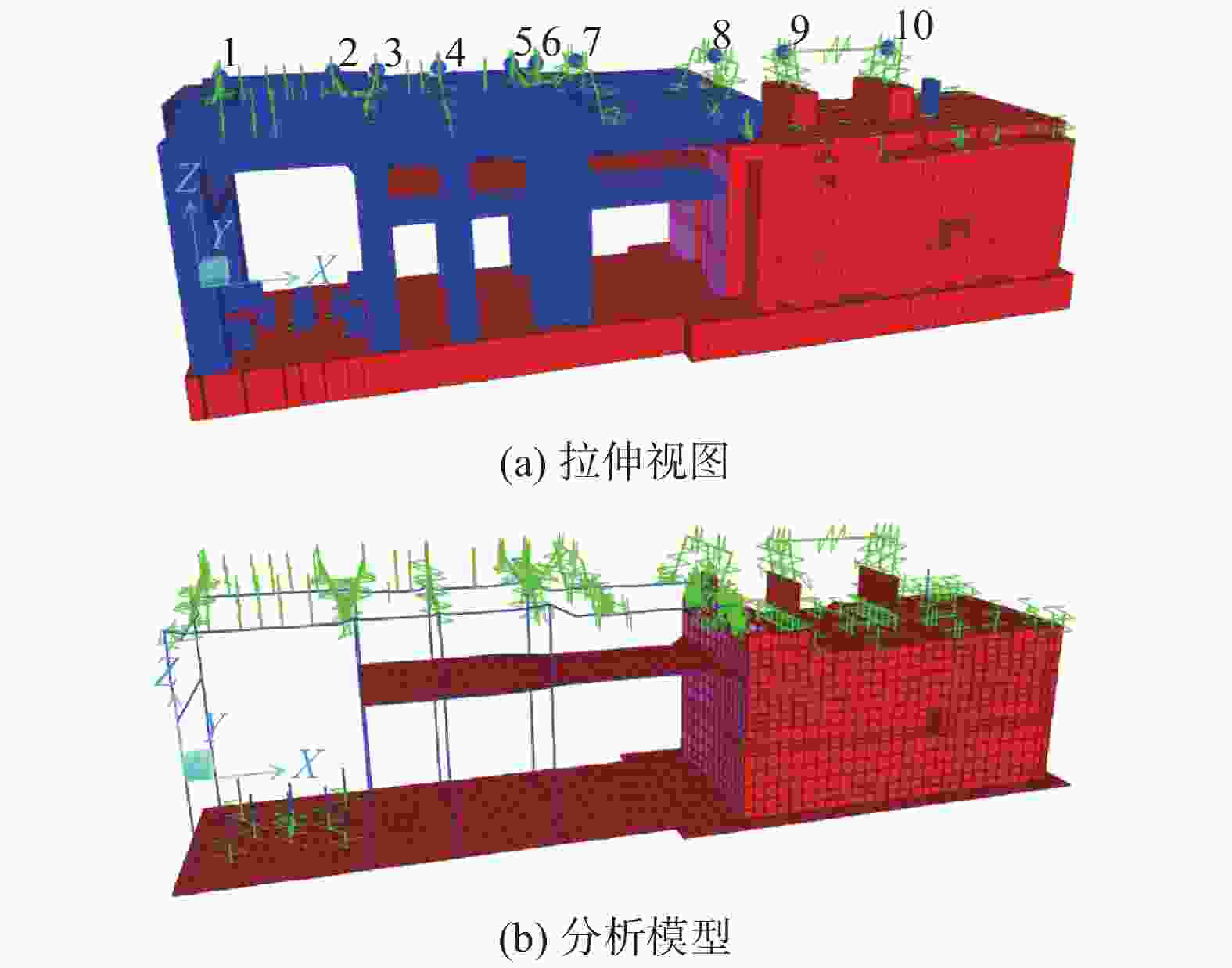
      Figure 2.  Finite element model of foundation of H-class combined cycle gas-steam turbine generator

    • 模态是结构的固有振动特性,每一个模态都有其固有频率、阻尼比和模态振型。通过模态分析可以了解H级燃机基础在正常运行频率范围内的各阶主要模态特征,从而判断结构在此频率段范围内的实际振动响应。通过SAP2000软件对H级燃机基础进行模态分析,提取前146阶的模态信息,部分模态信息如表2

      模态频率/
      Hz
      周期/
      s
      模态质量参与系数
      XYZ
      13.900.256 31.55E-063.35E-012.42E-06
      25.140.194 42.91E-053.06E-011.66E-06
      36.190.161 58.18E-016.01E-061.90E-04
      48.360.119 73.02E-068.76E-054.78E-07
      511.440.087 41.63E-063.40E-011.90E-04
      612.230.081 81.20E-034.15E-034.95E-05
      6737.670.026 51.25E-058.14E-085.30E-04
      10050.070.020 03.21E-076.80E-079.05E-07
      12762.420.016 08.53E-081.84E-079.31E-06
      14669.900.014 32.99E-083.73E-093.02E-06

      Table 2.  Modal frequencies of foundation of H class gas turbine

      H级燃机基础的第一阶频率为3.90 Hz,以横向振动为主。H级燃机的转速为3000 r/min,额定运行频率${f}_{\mathrm{m}}$=50 Hz,燃机基础的固有频率67阶到127阶处于$ 50\times \left(1\pm 25\%\right) $ Hz之间,当燃机的实际运行转速与固有频率接近时将引起共振,为避免燃机基础在燃机额定运行工况下产生过大振幅,通常采用谐响应分析的方法获得燃机基础运行频率下的振动情况,并按规范控制转子的振幅,当振动不能满足控制标准时,通常采用调整梁柱等截面尺寸的方式来改变基座的动力性能。

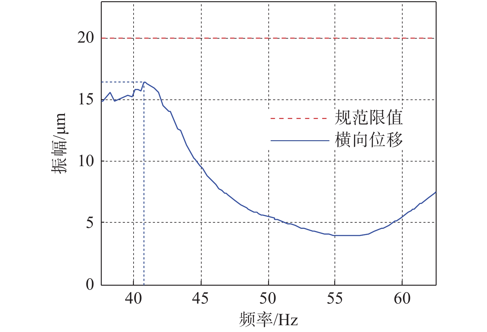
    • 一般情况下,采用多质点分别施加单向扰力(水平或竖向)进行分析,质点的振动位移按同一方向各扰力在该节点产生的同一方向振动位移的平方和开方(SRSS)求得[13]。分析得到H级燃机基础最大的振动位移发生在横向扰力作用工况的质点10的横向位移,采用SRSS法组合横向位移在频率40.75 Hz时达到最大值16.40 μm < 20 μm(国标限值)。同时,横向扰力下质点10在额定频率50 Hz处横向位移为5.50 μm远小于20 μm的限值,均满足国标容许振动位移峰值要求。横向扰力下质点10采用SRSS组合的横向振动位移曲线如图3所示。

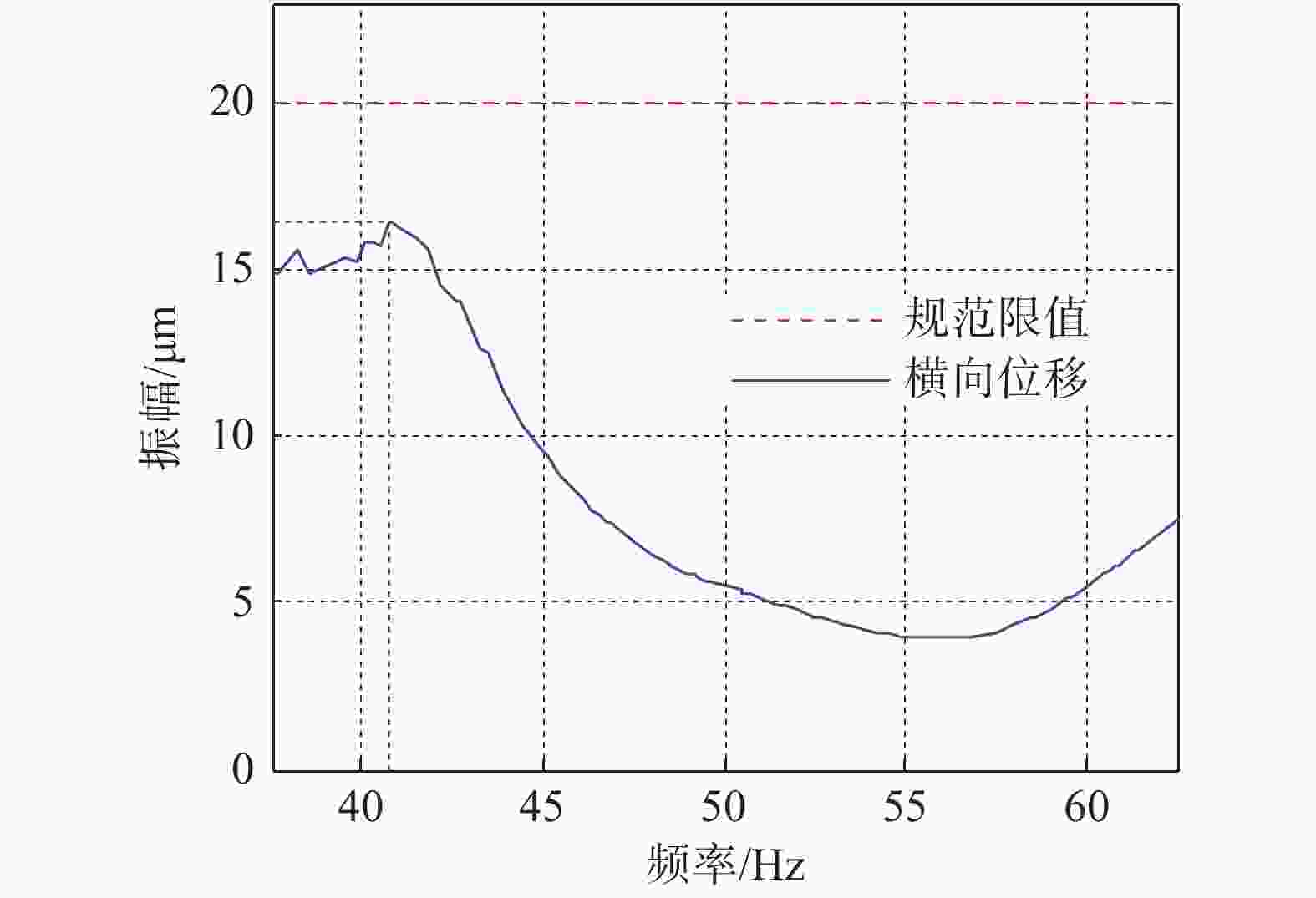
      Figure 3.  Combined lateral displacement of mass point 10 under the action of lateral disturbing force by the SRSS method

    • 为获得所有可能的出现的位移情况,采用多质点分别施加双向扰力进行分析。由于轴承转子间有膜刚度及阻尼的存在,作用在基座上的横向、竖向扰力之相位差不再是90°,此处考虑相位差为70°,80°,90°,100°,110°五种情况,即分别将每个质点同时施加相位相差为上述五种角度的水平和竖向动扰力[14-16]。分析得到各个质点振动位移亦是关于激振频率的正弦函数,各质点振动位移可能存在的相位角在0°~360°为等可能事件[17]。考虑SRSS法求得的最大位移的情况,即质点10在40.75 Hz的横向位移,各曲线的横向振动位移峰值矩阵${{\boldsymbol{u}}}_{10{\rm{h}}k}$如式(10)所示。

      $$ {{\boldsymbol{u}}}_{10{\rm{h}}k}=\left[\begin{array}{cc}\begin{array}{c}0.244\;4\\ 0.391\;6\\ 0.074\;8\\ 0.104\;0\\ 0.024\;7\\ 0.022\;2\\ 0.277\;4\\ 0.537\;0\\ 8.544\;0\\ 14.000\;0\;\;\;\end{array}& \begin{array}{ccc}\begin{array}{c}0.244\;8\\ 0.391\;1\\ 0.074\;4\\ 0.101\;0\\ 0.024\;9\\ 0.022\;4\\ 0.279\;1\\ 0.538\;9\\ 8.523\;0\\ 14.000\;0\;\;\;\end{array}& \begin{array}{c}0.244\;9\\ 0.390\;5\\ 0.073\;7\\ 0.098\;2\\ 0.024\;9\\ 0.022\;6\\ 0.280\;7\\ 0.541\;2\\ 8.502\;0\\ 14.000\;0\;\;\;\end{array}& \begin{array}{cc}\begin{array}{c}0.244\;9\\ 0.389\;7\\ 0.072\;7\\ 0.095\;7\\ 0.024\;9\\ 0.022\;8\\ 0.282\;3\\ 0.543\;8\\ 8.481\;0\\ 14.000\;0\;\;\;\end{array}& \begin{array}{c}0.244\;7\\ 0.388\;8\\ 0.071\;5\\ 0.093\;5\\ 0.024\;7\\ 0.022\;9\\ 0.283\;8\\ 0.546\;6\\ 8.461\;0\\ 14.000\;0\;\;\; \end{array}\end{array}\end{array}\end{array}\right] $$ (10)

      其中,
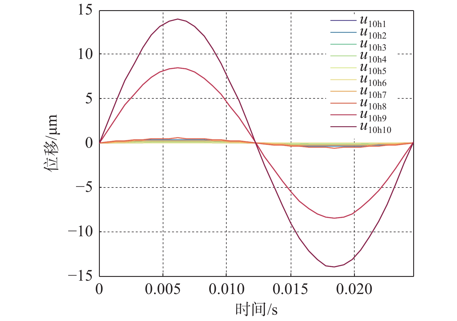
${{\boldsymbol{u}}}_{10\mathrm{h}k}$中的第1列到第5列表示分别表示横向和竖向扰力相位差为70°,80°,90°,100°,110°五种情况;第i行表示扰力作用在第i个质点时对质点10产生的横向振动位移峰值。

      特例取横向和竖向扰力之相位差为90°,所有扰力工况在质点10产生的横向振动位移的相位角同时为零,那么各组扰力工况在质点10产生的横向位移时程曲线如图4所示。

      Figure 4.  Time history curve of lateral displacement of mass point 10

      如果采用式(9)对这10组横向振动位移进行线性叠加,由于各位移相位角在0°~360°随机取值,即使每条横向振动位移相位角按0°∶1°∶360°取值,那么也会产生36010个组合结果,组合计算量非常大,并呈现幂次级增长,这亦是目前普通计算机难以完成的数据量。而如果相位角的间隔取的过大,又会造成大量数据丢失,并使得最终组合结果在概率统计上失真。

      特别地,可以观察到在40.75 Hz质点1~8的振动位移峰值远小于质点9、质点10的振动位移峰值,此频率的质点10的横向振动位移主要贡献来源于质点9、质点10的贡献。因此,对采用质点1~10和只采用质点9、质点10的横向振动位移组合值进行对比分析,振动位移对比结果见表3

      扰力相位差方法质点1~10/
      μm
      质点9~10/
      μm
      误差/%
      SRSS16.4016.380.12
      70°LSM24.2222.546.94
      80°LSM24.2022.526.94
      90°LSM24.1822.506.95
      100°LSM24.1622.486.95
      110°LSM24.1422.466.96

      Table 3.  Comparison of lateral displacement of different combinations

      表3可知采用质点1~10和采用质点9、质点10在40.75 Hz的横向振动位移计算结果相差不大,并在竖向扰力和横向扰力相位差为70°~90°计算位移振动变化很小。为大量减少计算,取扰力相位差为90°,质点9和质点10两组横向振动位移进行线性叠加计算,每组横向振动位移相位角取0°∶1°∶359°,则通过LSM法质点10总共可计算得到
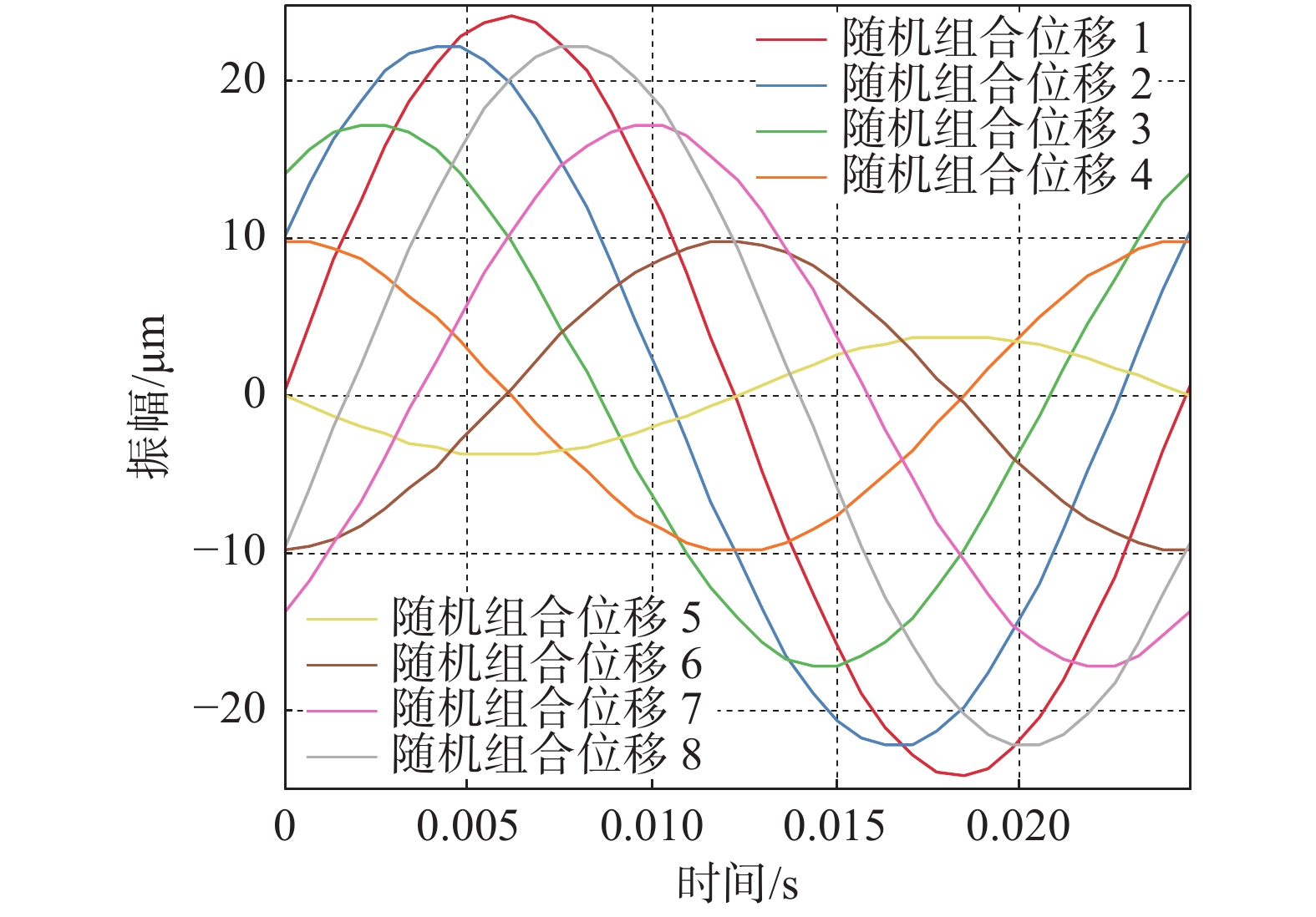
$ {360}^{2}=1.296\times {10}^{5} $个横向位移结果。

      通过计算得到质点10的LSM法的最大横向位移为24.18 μm,大于SRSS法求得的横向位移16.40 μm。质点10采用线性叠加法计算得到的部分横向振动位移时程曲线如图5所示。

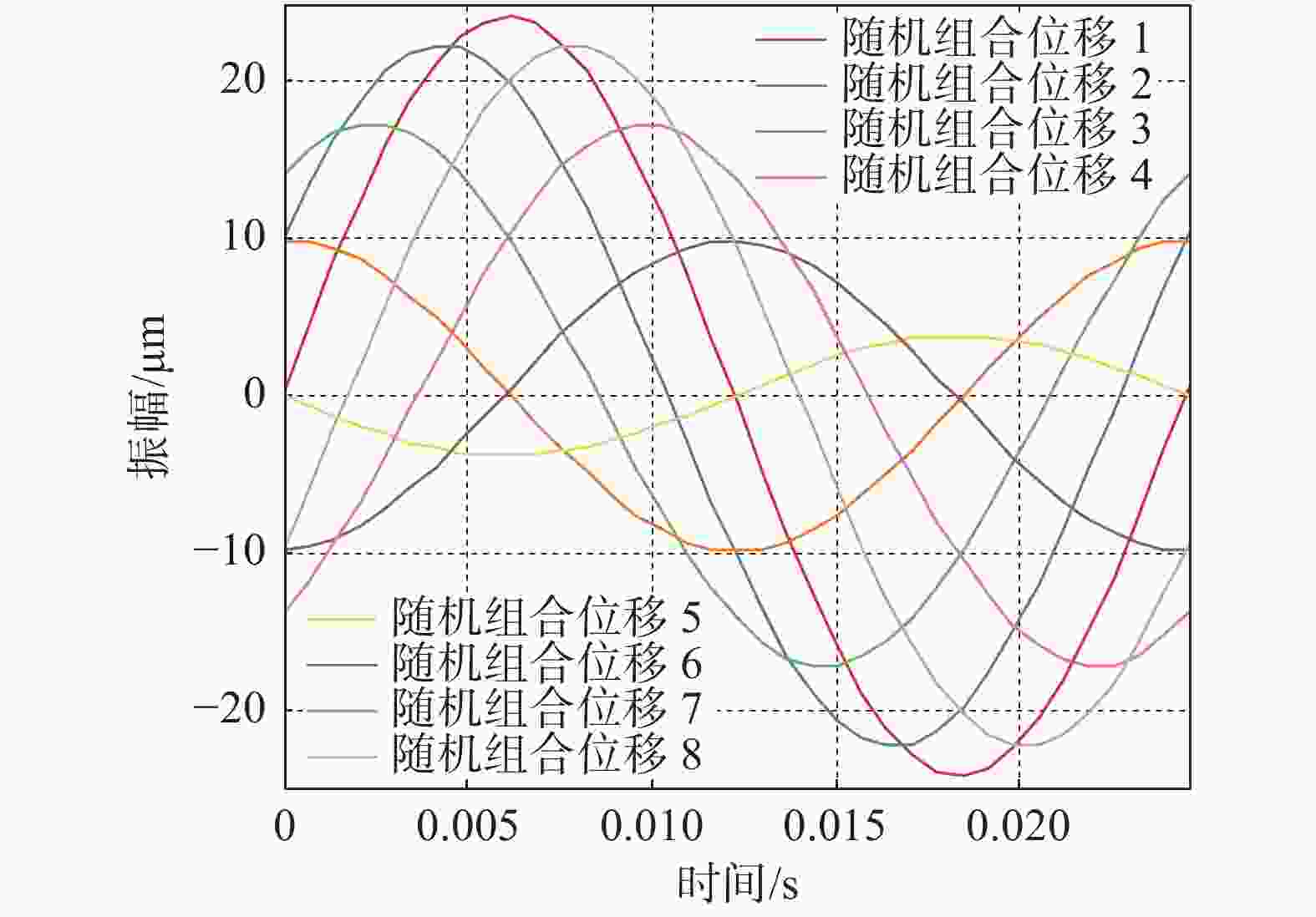
      Figure 5.  Time history curve of lateral displacement of mass point 10 by the LSM method

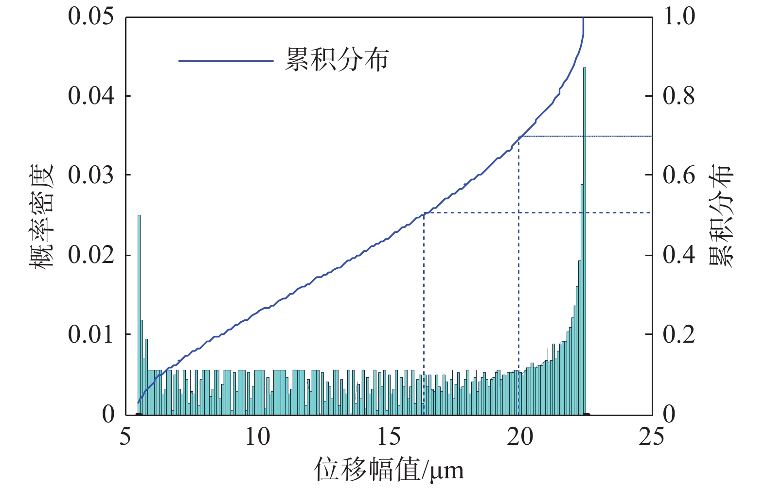
    • 每组扰力相位差工况,基于质点9、质点10在40.75 Hz横向振动位移线性叠加法的计算得到的$ 1.296\times {10}^{5} $个横向位移结果,假定其所有值为等可能事件。因此,取扰力相位差为90°采用频率分布直方图方法统计所有结果的分布规律。其频率分布如图6所示。

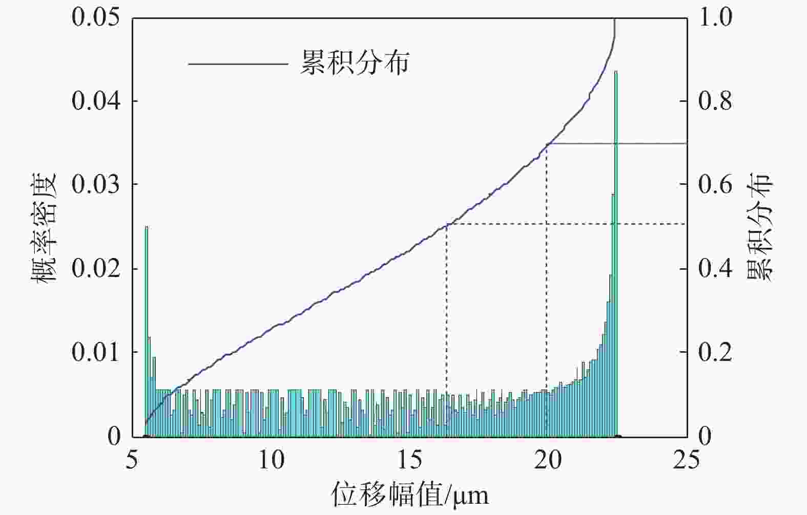
      Figure 6.  Frequency distribution histogram of lateral displacement of mass point 10

      图6可知,质点10在40.75 Hz横向振动位移不超过20 μm的可靠概率约为70%,不超过16.40 μm的可靠概率约为50%,此处频率40.75 Hz较为远离额定频率50 Hz,并且在额定频率50 Hz下质点10的SRSS法横向振动位移5.5 μm较小,满足国标容许振动位移峰值20 μm的要求。

      SRSS法将振动位移在组合上进行了很大程度的减小,其综合考虑了振动相位角、动扰力和阻尼比的取值不确定性。因为,在设计阶段动扰力一般较实际取得大,比如通常燃机转子动平衡等级为G2.5,而在设计计算时采用G6.3进行考虑。因此,SRSS法的结果看似相对于LSM法的结果可靠概率并不高,但考虑到动扰力等其他输入参数时,SRSS法可靠概率将在实际的综合水平中大幅度提高。同时,SRSS法在一定程度上保证了动力设备基础的经济性。因此,SRSS法是目前常规采用的组合方法。

      但如果是质点的最大振动位移出现在靠近运行频率附近,并且位移接近规范限值时,对于特别敏感或者重要的动力基础宜控制其可靠概率,可采用增大裕度的方法来提高其可靠概率。

    • 通过有限元软件建立高位布置H级联合循环燃气-蒸汽轮发电机基础三维有限元模型,采用平方和开方(SRSS)法求得各质点的振动位移,由于各质点动扰力之间角度的不确定,采用双向扰力下的线性叠加法计算所有可能的振动位移并统计其概率分布。

      1)燃机基础的第一阶频率为3.90 Hz,以横向振动为主。

      2)H级燃机基础质点10在40.75 Hz横向振动位移SRSS法组合值为16.40 μm,最大可能横向振动位移值为24.18 μm,SRSS法的可靠概率约为50%。

      3)基于SRSS法获得的多质点振动位移值并不是最大值,其具有一定的可靠概率,对于特别敏感或者重要的动力基础分析中宜控制其可靠概率,可采用增大裕度的方法来提高其可靠概率。

Reference (17)

Catalog

    /

    DownLoad:  Full-Size Img  PowerPoint
    Return
    Return