• Peer Review
  • Non-profit
  • Global Open Access
  • Green Channel for Rising Stars
Volume 9 Issue S2
Jan.  2023
Turn off MathJax
Article Contents

LI Cong, FANG Qi. Research on Numerical Simulation of Cohesive Behavior in Shearkey-Less Grouted Connection[J]. SOUTHERN ENERGY CONSTRUCTION, 2022, 9(S2): 1-5. doi: 10.16516/j.gedi.issn2095-8676.2022.S2.001
Citation: LI Cong, FANG Qi. Research on Numerical Simulation of Cohesive Behavior in Shearkey-Less Grouted Connection[J]. SOUTHERN ENERGY CONSTRUCTION, 2022, 9(S2): 1-5. doi: 10.16516/j.gedi.issn2095-8676.2022.S2.001

Research on Numerical Simulation of Cohesive Behavior in Shearkey-Less Grouted Connection

doi: 10.16516/j.gedi.issn2095-8676.2022.S2.001
  • Received Date: 2021-12-07
  • Rev Recd Date: 2022-02-18
  • Available Online: 2023-01-04
  • Publish Date: 2023-01-04
  •   Introduction  Grouted connections of offshore wind foundation structures exhibit complicated behavior, and in particular, the interaction between grouted material and steel pipe is crucial to the overall performance.   Method  This paper mainly introduced and analyzed the behavior attribute configuration on the simulation interface of the cohesive model. Cohesive model theory was introduced in terms of cohesive behavior of cohesive model, criteria for interface damage judgment and criteria for interface damage evolution. Based on a typical shearkey-less grouted connection, conventional configuration during modeling and contact configuration of cohesive model were introduced.   Result  Through analysis, the feasibility of implementing cohesive behavior in the cohesive model in ABAQUS is proven.   Conclusion  The cohesive model proposed by this paper can simulate the collaborative deformation of steel cylinder wall and grouting body, Mises stress distribution of the steel cylinder wall, Tresca stress distribution of the grouting body and load-displacement curve well.
  • [1] 王衔, 陈涛, 赵淇, 等. DNV规范(2014)海上风机基础灌浆连接段抗弯性能设计理论研究 [J]. 海洋工程, 2016, 34(3): 140-150. DOI:  10.16483/j.issn.1005-9865.2016.03.016.

    WANG X, CHEN T, ZHAO Q, et al. Design theory of bending capacity of grouted connections in offshore wind turbines foundation based on DNV specification(2014) [J]. The Ocean Engineering, 2016, 34(3): 140-150. DOI:  10.16483/j.issn.1005-9865.2016.03.016.
    [2] ANDERSEN M S, PERTERSEN P. Structural design of grouted connection in offshore steel monopile foundations [C]//Det Norske Veritas. Global Windpower Conference, Roskilde, Denmark: 2004. Denmark: Det Norske Veritas, 2004: 1-13.
    [3] LÖHNING T, VOβBECK M, KELM M. Analysis of grouted connections for offshore wind turbines [J]. Energy, 2013, 166(4): 153-161. DOI:  10.1680/ener.12.00009.
    [4] WILKE F. Load bearing behavior of grouted joints subjected to predominant bending [D]. Hannover, Lower Saxony: Leibniz University Hannover, 2013.
    [5] CHEN T, WAND X, YUAN G K, et al. Fatigue bending test on grouted connections for monopile offshore wind turbines [J]. Marine Structures, 2018, 60(7): 52-71. DOI:  10.1016/j.marstruc.2018.03.005.
    [6] 韩瑞龙, 施卫星, 周洋. 灌浆套筒连接技术及其应用 [J]. 结构工程师, 2011, 27(3): 149-153. DOI:  10.15935/j.cnki.jggcs.2011.03.024.

    HAN R L, SHI W X, ZHOU Y. Grout sleeve connection and relevant applications [J]. Structural Engineers, 2011, 27(3): 149-153. DOI:  10.15935/j.cnki.jggcs.2011.03.024.
    [7] 康海贵, 孙道明, 莫仁杰, 等. 海上风机桩基础与上部结构灌浆连接段优化分析 [J]. 沈阳建筑大学学报(自然科学版), 2013, 29(1): 77-85.

    KANG H G, SUN D M, MO R J, et al. Structural optimization of grouted connection in offshore wind turbine foundations [J]. Journal of Shenyang Jianzhu University (Natural Science Edition), 2013, 29(1): 77-85.
    [8] ABAQUS. ABAQUS standard user's manual [M]. Providence, RI, USA: Simulia, 2016.
    [9] SRILAKSHMI R, RAMJI M, CHINTHAPENTA V. Fatigue crack growth study of CFRP patch repaired Al 2014-T6 panel having an inclined center crack using FEA and DIC [J]. Engineering Fracture Mechanics, 2015, 134: 182-201. DOI:  10.1016/j.engfracmech.2014.12.012.
    [10] 赵淇, 陈涛, 王衔, 等. 海上风机导管架支撑结构灌浆连接段数值分析 [J]. 结构工程师, 2016, 32(5): 59-64. DOI:  10.15935/j.cnki.jggcs.2016.05.009.

    ZHAO Q, CHEN T, WANG X, et al. Numerical analysis of grouted connection in jacket support structures for offshore wind turbine [J]. Structural Engineers, 2016, 32(5): 59-64. DOI:  10.15935/j.cnki.jggcs.2016.05.009.
    [11] LOTSBERG D, SEREDNICKI A, LERVIK A. Design of grouted connections for monopile offshore structures: results from two joint industry projects [J]. Stahlbau, 2012, 81(9): 695-704. DOI:  10.1002/stab.201201598.
  • 通讯作者: 陈斌, bchen63@163.com
    • 1. 

      沈阳化工大学材料科学与工程学院 沈阳 110142

    1. 本站搜索
    2. 百度学术搜索
    3. 万方数据库搜索
    4. CNKI搜索

Figures(7)  / Tables(1)

Article Metrics

Article views(95) PDF downloads(29) Cited by()

Related

Research on Numerical Simulation of Cohesive Behavior in Shearkey-Less Grouted Connection

doi: 10.16516/j.gedi.issn2095-8676.2022.S2.001

Abstract:   Introduction  Grouted connections of offshore wind foundation structures exhibit complicated behavior, and in particular, the interaction between grouted material and steel pipe is crucial to the overall performance.   Method  This paper mainly introduced and analyzed the behavior attribute configuration on the simulation interface of the cohesive model. Cohesive model theory was introduced in terms of cohesive behavior of cohesive model, criteria for interface damage judgment and criteria for interface damage evolution. Based on a typical shearkey-less grouted connection, conventional configuration during modeling and contact configuration of cohesive model were introduced.   Result  Through analysis, the feasibility of implementing cohesive behavior in the cohesive model in ABAQUS is proven.   Conclusion  The cohesive model proposed by this paper can simulate the collaborative deformation of steel cylinder wall and grouting body, Mises stress distribution of the steel cylinder wall, Tresca stress distribution of the grouting body and load-displacement curve well.

LI Cong, FANG Qi. Research on Numerical Simulation of Cohesive Behavior in Shearkey-Less Grouted Connection[J]. SOUTHERN ENERGY CONSTRUCTION, 2022, 9(S2): 1-5. doi: 10.16516/j.gedi.issn2095-8676.2022.S2.001
Citation: LI Cong, FANG Qi. Research on Numerical Simulation of Cohesive Behavior in Shearkey-Less Grouted Connection[J]. SOUTHERN ENERGY CONSTRUCTION, 2022, 9(S2): 1-5. doi: 10.16516/j.gedi.issn2095-8676.2022.S2.001
  • 近年来由于风能清洁可再生的优势,海上风力发电得到迅猛发展。对于采用分体式施工的风机基础结构,直接与塔筒相连的上部结构与基础下部之间需要通过某种节点型式连接成整体。

    到目前为止,灌浆连接是在全球海上风电场建设中应用最为成熟的连接方式,有施工难度低、受力性能好等优势。ABAQUS数值模拟是灌浆连接段分析的重要手段,而钢材与灌浆料之间的接触形式,近年来没有统一定论[1]。在Andersen的分析中[2],采用壳单元来模拟桩管和过渡段,采用实体单元模拟灌浆层,钢材与灌浆料的相互作用采用理想库伦摩擦模型;Löhning的有限元模型中同样采用壳单元来模拟桩管和过渡段,进一步考虑了灌浆料与钢管之间的接触作用以及灌浆体中的早期裂缝[3];Wlike建立了弹簧单元-接触组合模型来对灌浆连接段进行数值分析[4]。本文在前人研究的基础上,考虑钢材和灌浆料之间的粘结行为,采用粘聚力模型对无剪力键灌浆连接段进行有限元数值分析[5-7]

    • 灌浆连接段中钢材与灌浆体之间的自然粘结或设置抗剪件是保证灌浆连接段中两者保持位移协调并共同工作的方法。钢质筒壁与灌浆体之间的粘结作用,使钢材和灌浆体成为共同传递荷载的整体。灌浆连接段的受力和变形性能取决于筒壁和灌浆体之间的粘结性能,因此,合理模拟两者之间的接触作用,是至关重要的。在ABAQUS中,有较多设置接触的操作,本文主要采用粘聚力模型对界面的行为进行模拟[8]

    • 在粘聚力模型的行为属性中,界面接触单元节点间距即是界面行为特性开裂位移。换言之,单元接触面上节点的间距即为接触面上投影点切向和法向之间的相对距离,单位面积内的法向力和切向力即为接触属性中定义的粘结力,该相对距离和粘结力依据内聚力模型中界面应力-开裂位移本构关系相联系。

      界面见内聚力的形态过程可以通过二维单元的数值模拟来具体表达,如图1所示。

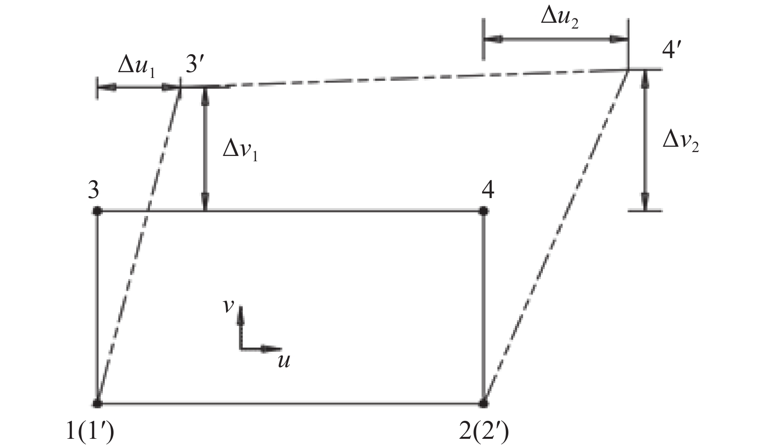
      Figure 1.  Schematic diagram of cohesive contact calculation

      图1可发现,1、2、3、4节点位置代表界面滑移前的状态,1′、2′、3′、4′对应界面滑移后的各节点的位置。

    • 粘结力本构曲线中进入线性软化的分界点决定了粘聚力模型界面损伤阶段的开始点。在界面接触中,只要接触面的应变或应力达到损伤准则,界面就被判定为进入损伤阶段。ABAQUS接触损伤设置中一共提供了4种判定准则供选择:最大分离、最大应力、二次分离和二次应力。目前,最大应力准则的应用最为多见,如式(1):

      $${\rm{max}}\left\{ {\dfrac{{\sigma }_{n}}{{\sigma }_{n}^{0}},\dfrac{{\sigma }_{s}}{{\sigma }_{s}^{0}},\dfrac{{\sigma }_{t}}{{\sigma }_{t}^{0}}} \right\}=1 $$ (1)

      式中:

      σn——界面上的法向应力(MPa);

      σs——界面上的切向应力(MPa);

      σt——界面上的切向应力(MPa)。

      这三个应力的数值不是常量,而是随界面的滑动不断变化的。

      分母中的$ {\sigma }_{n}^{0}、{\sigma }_{s}^{0}、{\sigma }_{t}^{0} $代表界面处于弹性阶段时对应的最大应力。当(1)式成立时,说明接触面上的粘聚力已开始破坏,界面的应力-开裂曲线进入损伤软化阶段。

    • 损伤演化是指界面上的粘聚力达到损伤判定准则后,界面刚度退化的速率。在本构关系曲线中,该速率体现为软化后曲线的斜率,用D表示。D的变化区间是0到1,界面破坏时D=1,此时界面上的单元节点已失去承载能力。损伤演化有线性和指数型等多种模型,目前广为应用且计算较为简便的是线性演化模式[9]

    • ABAQUS软件的有限元分析流程一般由3部分构成:前处理、有限元计算和后处理。本文基于无剪力键灌浆连接段的有限元计算算例,对应用ABAQUS软件进行数值计算涉及到的几何建模、材料属性设置、截面属性设置、计算部件装配、分析步定义、粘聚力模型粘结行为相关的接触设置、荷载属性设置、边界条件属性设置、几何模型离散化和计算结果后处理等步骤进行介绍。其中,粘聚力模型的设置方法,将作重点分析。

    • 几何部件是ABAQUS模型的基本构成部分,模型中包含的各个零件均应有相对应的几何部件。算例中在部件模块里共建立3个部件:灌浆筒壁、灌浆层和套管。所有部件均为在三维模型空间中建立的可变型部件,其中灌浆连接段钢管和浆体部分均采用8节点6面体线性缩减积分实体单元(C3D8R 单元)。为保证计算精度,在环向方向,钢管与灌浆料均划分50层;在厚度方向,钢管划分3层,灌浆料划分5层。本文以1个无剪力键灌浆连接段构件为例进行介绍,几何参数见表1[10],灌浆连接段结构尺寸见图2

      内钢管外钢管灌浆层灌浆段
      外径Dp厚度tp外径DJL厚度tJL厚度tg全长Lg
      1 371501 572501509 243

      Table 1.  Geometric dimension of grouted assembly numerical model mm

      Figure 2.  Dimension of grouted connection

    • 有限元模型由钢和灌浆料两种材料构成。钢是各向同性材料,用VonMise屈服准则和随动强化法则对其塑性行为进行模拟。钢的屈服强度fy取为355 MPa,泊松比μs取为0.3,弹性模量Es取为206 GPa。灌浆料是各向异性材料,用混凝土塑性损伤模型对其力学性能进行模拟。弹性模量Eg取为51 GPa,泊松比γ为0.2,抗压强度fg为87 MPa,抗拉强度ft为4.6 MPa。

    • 在有限元模型底部施加固定约束。利用参考点耦合(Coupling)模型顶面,用参考点控制模型顶面的自由度,并对参考点施加荷载或者位移进行加载。例中对参考耦合点施加集中力和集中弯矩,分别为Fx为−10.974 MN、Fy为101 kN、Fz为340 kN,Mx为−306 kN·m、My为−3.441 MN·m、Mz为−904 kN·m。

    • 在本文中灌浆连接段建模是采用分离式建模的方式,有限元模型需要通过部件与部件之间的接触联系成一个整体。

    • 有限元模型的接触定义包括两个方向,分别为法向接触属性和切向接触属性。法向接触属性用硬接触模拟灌浆筒壁与灌浆体之间的挤压作用。切向接触属性用无粘结库伦摩擦模型模拟灌浆筒壁与灌浆体之间相互错动产生的摩擦力。根据Lotsberg的实践经验,界面摩擦系数μ在长期使用荷载下建议取为0.4,对于试件建议取为0.7[11]。法线方向和切线方向的接触均采用“罚函数法”进行计算。

    • 如前文所述,如果考虑钢材与灌浆料之间的粘结效应,则应在ABAQUS中进行粘聚力模型设置。在进行常规设置之后,应在对应在ABAQUS中需要添加粘聚力行为以及损伤两项行为。

      粘结滑移刚度设置方面,考虑接触面法向应力和粗糙度变化时,接触面切向粘结滑移刚度K变化的经验取值范围为5.0~13.5 MPa/mm,当无实验数据支持时,可保守取5.0 MPa/mm,有条件的项目可根据灌浆原型实验结果进行选取;而法向因为定义了硬接触,所以此处刚度取0。ABAQUS接触损伤设置方面,选用最大应力准则,并设置弹性阶段的最大应力为1.5 MPa;界面损伤演化方面,选择双线性张力位移准则,最终滑移与峰值滑移值的比值取2。

    • 在设计荷载作用下,灌浆连接段试件不同高度位置的变形如图3所示。连接段的最大位移为16.75 mm,出现在顶部,变形在钢管部分体现更明显。

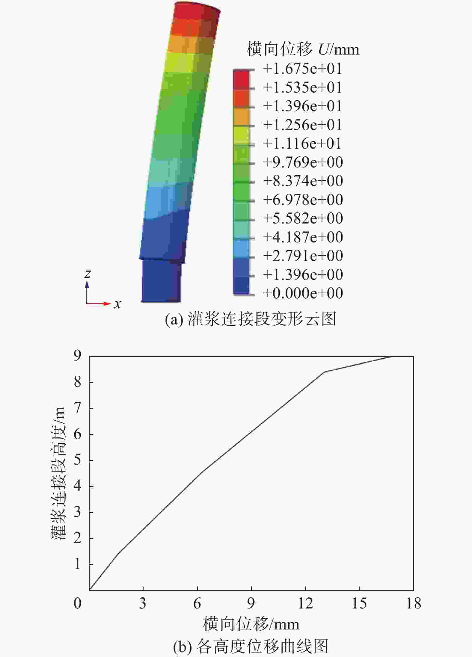
      Figure 3.  Deformation of grouted connection

    • 外侧钢筒Mises应力分布如图4所示。由于承受较大的弯矩荷载,模型分为受压侧与受拉侧,上部大、下部小。应力最大值位于受压侧钢管上部,值为88.8 MPa,应力最小值位于受拉侧钢管中部偏下,值为39.4 MPa。通过观察可发现,Mises应力的分布与设计预期相符。

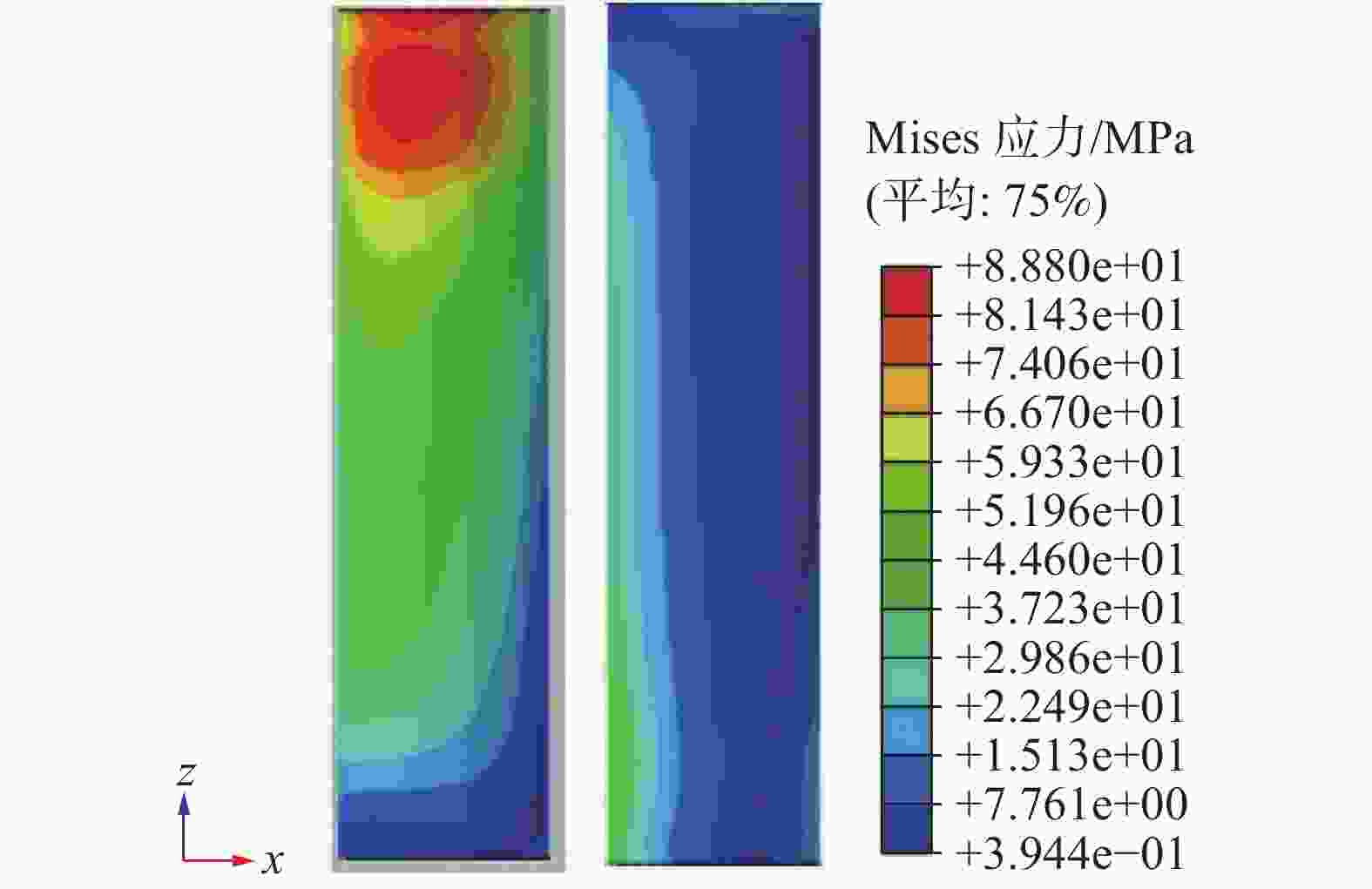
      Figure 4.  Mises stress of outer steel pipe

    • 内侧钢筒的Mises应力分布如图5所示。应力分布云图与外管分布相反,上部小下部大。与钢管外管相比,应力分布值较大,最大值为126.8 MPa,位于钢管最下部,最小值为0.34 MPa,位于钢管另一侧的最上部。

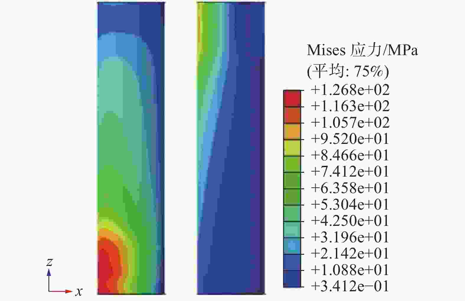
      Figure 5.  Mises stress of inner steel pipe

    • 灌浆体的Tresca应力分布如图6所示。由于没有剪力键的作用,以及设计荷载分布的影响,灌浆层Tresca应力呈现上下对称,前后对应的分布形态,上部和下部大,中间部分受力分布较均匀;前后分布呈受压侧大,受拉侧小形态。应力较小,最大值为6.6 MPa,位于受压侧浆体最上部,最小值为0.29 MPa,位于受拉侧浆体中间部分。

      Figure 6.  Tresca stress of grouting body

    • 灌浆段顶部的荷载位移曲线如图7所示,取X向荷载及位移,由于设计荷载较小,该部分仍处于弹性阶段,所以荷载位移曲线呈现直线形状。

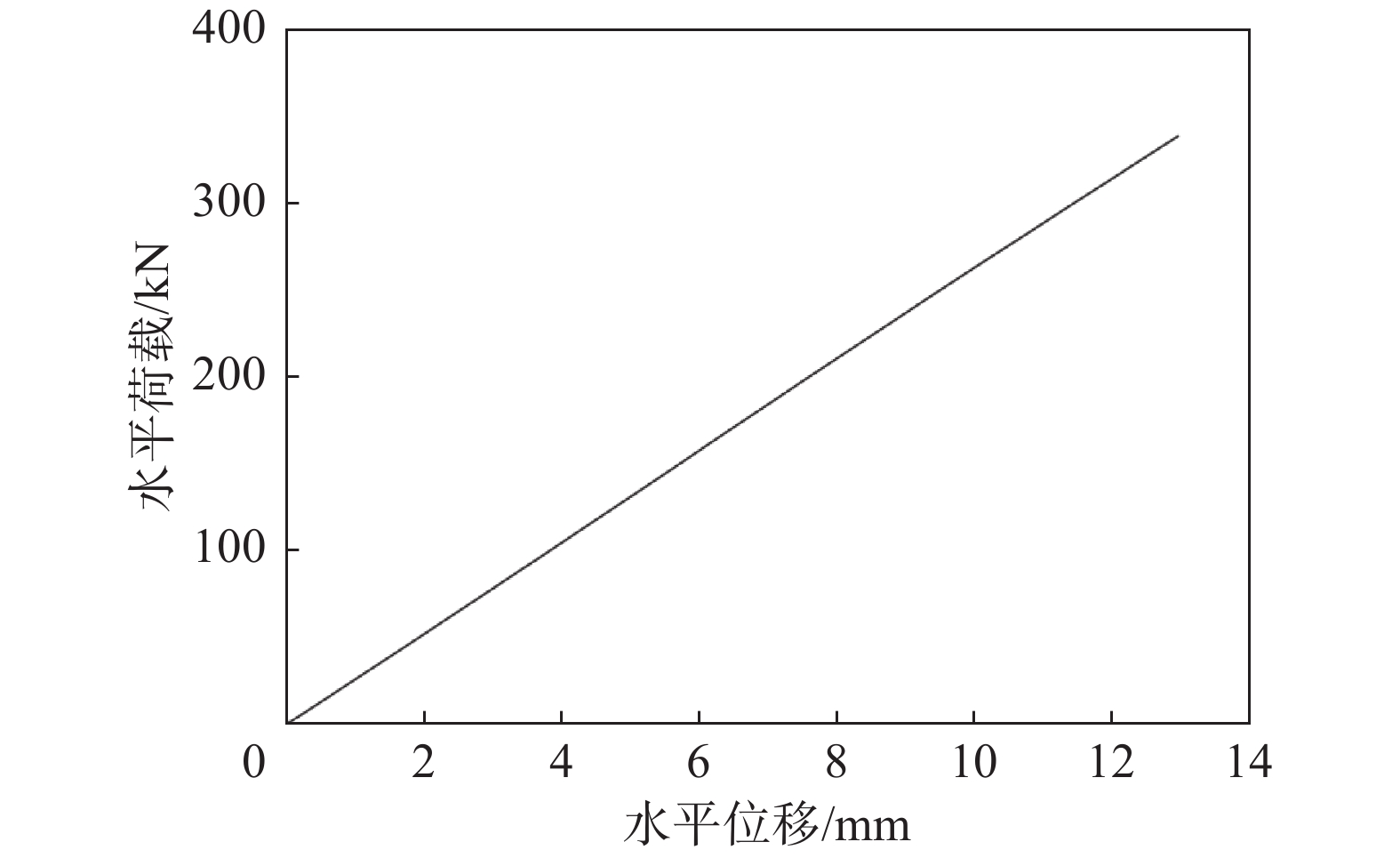
      Figure 7.  Load-displacement curve at the top of steel pipe

    • 灌浆连接段中不同材料之间的作用,可以通过建立粘聚力模型进行数值分析。通过对试件的分析可知,钢质筒壁和灌浆体的协同变形时,钢管部分的变形比复合截面部分更为明显;外侧钢筒Mises应力受压侧上部大,受拉侧下部小;内侧钢筒Mises应力受压侧下部大,受拉侧上部小;灌浆体Tresca应力受压侧上下部分大,受拉侧中间部分小;当设计荷载较小时,荷载位移曲线呈直线状。

Reference (11)

Catalog

    /

    DownLoad:  Full-Size Img  PowerPoint
    Return
    Return