• Peer Review
  • Non-profit
  • Global Open Access
  • Green Channel for Rising Stars
Volume 10 Issue 4
Jul.  2023
Turn off MathJax
Article Contents

WANG Kai, WU Zonghao, HAN Ruolang, LE Conghuan, MAI Zhihui, WU Han. Model Test Study on the Influence of the Spudcan Penetration Depth on the Horizontal Bearing Characteristics of Jack-Up Vessel for Wind Turbine Installation in Sandy Soil[J]. SOUTHERN ENERGY CONSTRUCTION, 2023, 10(4): 1-10. doi: 10.16516/j.gedi.issn2095-8676.2023.04.001
Citation: WANG Kai, WU Zonghao, HAN Ruolang, LE Conghuan, MAI Zhihui, WU Han. Model Test Study on the Influence of the Spudcan Penetration Depth on the Horizontal Bearing Characteristics of Jack-Up Vessel for Wind Turbine Installation in Sandy Soil[J]. SOUTHERN ENERGY CONSTRUCTION, 2023, 10(4): 1-10. doi: 10.16516/j.gedi.issn2095-8676.2023.04.001

Model Test Study on the Influence of the Spudcan Penetration Depth on the Horizontal Bearing Characteristics of Jack-Up Vessel for Wind Turbine Installation in Sandy Soil

doi: 10.16516/j.gedi.issn2095-8676.2023.04.001
  • Received Date: 2023-05-15
  • Rev Recd Date: 2023-05-29
  • Available Online: 2023-07-25
  • Publish Date: 2023-07-10
  •   Introduction  As an important construction equipment in the development of offshore wind power, studying the bearing performance of the jack-up vessel for wind turbine installation in the in-situ state to ensure its operation safety is of great significance.   Method  In this paper, taking the jack-up installation vessel as the research object, the horizontal bearing performance of the jack-up installation vessel and the variation law of the surrounding earth pressure at four different penetration depths of spudcans in homogeneous sandy soil were studied by combining with the indoor model tests and finite element method.   Result  The results show that with the increasing of the penetration depth, the horizontal bearing capacity of the jack-up installation vessel is on an approximate linear growth trend. The penetration depth of 10 cm led to an increase of the horizontal bearing capacity by 38.02% compared with 4 cm penetration depth, and the corresponding horizontal displacement also show an increasing trend. Under the action of horizontal loads, the bearing mode of spudcans is characterized by compression of spudcans on the loading side and tension of spudcans on the non-loading-side. The pressure change law of the soil on the surface of spudcans is the same. At the penetration depth of 10 cm, the maximum variation in soil pressure at the bottom of spudcans on the loading side is 38.37 kPa, which increased by 126.2% compared to the penetration depth of 4 cm. In addition, significant variations in soil pressure are observed on the lower surface of the loading-side spudcans and the upper surface of the non-loading-side spudcans.   Conclusion  Under the action of horizontal load, the force mode of the jack-up installation vessel is the tension-compression mode, and increasing the penetration depth of spudcans in sandy soil can significantly enhance the horizontal bearing capacity. Therefore, in order to ensure the safety and operational capability of the wind turbine installation vessel, it is necessary to ensure sufficient penetration depth of spudcans.
  • [1] 郭凯, 张秀琦, 曹斌, 等. 海上风力发电可靠性影响因素分析及提升方法 [J]. 内蒙古电力技术, 2022, 40(5): 16-21. DOI:  10.19929/j.cnki.nmgdljs.2022.0075.

    GUO K, ZHANG X Q, CAO B, et al. Analysis of factors affecting reliability of offshore wind power and improvement methods [J]. Inner Mongolia electric power, 2022, 40(5): 16-21. DOI:  10.19929/j.cnki.nmgdljs.2022.0075.
    [2] 张力, 黄钺, 王洪庆, 等. 海上风电嵌岩桩水平承载力特性数值模拟研究 [J]. 南方能源建设, 2021, 8(3): 34-43. DOI:  10.16516/j.gedi.issn2095-8676.2021.03.005.

    ZHANG L, HUANG Y, WANG H Q, et al. Numerical simulation research on the horizontal bearing capacity of rock-socketed piles for offshore wind turbines [J]. Southern energy construction, 2021, 8(3): 34-43. DOI:  10.16516/j.gedi.issn2095-8676.2021.03.005.
    [3] 张强, 葛畅, 沈晓雷, 等. 竹根沙海域单桩基础竖向承载力特性数值模拟研究 [J]. 南方能源建设, 2021, 8(3): 44-50. DOI:  10.16516/j.gedi.issn2095-8676.2021.03.006.

    ZHANG Q, GE C, SHEN X L, et al. Numerical simulation research on the vertical bearing capacity of the single pile foundation in Zhugensha sea area [J]. Southern energy construction, 2021, 8(3): 44-50. DOI:  10.16516/j.gedi.issn2095-8676.2021.03.006.
    [4] 张海亚, 郑晨. 海上风电安装船的发展趋势研究 [J]. 船舶工程, 2016, 38(1): 1-7,30. DOI:  10.13788/j.cnki.cbgc.2016.01.001.

    ZHANG H Y, ZHENG C. Developing trend analysis of wind turbine installation vessel [J]. Ship engineering, 2016, 38(1): 1-7,30. DOI:  10.13788/j.cnki.cbgc.2016.01.001.
    [5] 黄瑛. 自升式平台插拔桩及二次插桩数值分析 [D]. 大连: 大连理工大学, 2018.

    HUANG Y. Numerical study of the penetration and extraction and the reinstallation of spudcans of jack-ups [D]. Dalian: Dalian University of Technology, 2018.
    [6] 刘阳. 自升式平台滑移问题及对平台结构影响分析 [D]. 北京: 中国石油大学(北京), 2017.

    LIU Y. Jack-up sliding and its influence on platform structure [D]. Beijing: China University of Petroleum (Beijing), 2017.
    [7] 刘智慧. 钻孔法减弱自升式平台滑移和穿刺风险的研究 [D]. 上海: 上海海事大学, 2021.

    LIU Z H. Investigation on perforation drilling to mitigate on the sliding risk during spudcan installation close to footprints and punch-through potential in sand overlying soft clay [D]. Shanghai: Shanghai Maritime University, 2021.
    [8] HOSSAIN M S, RANDOLPH M F. SS: Jack-up rig technology-new mechanism-based design approach for spudcan foundations on stiff-over-soft clay [C]//Anon. Proceedings of the Offshore Technology Conference, Houston, Texas, May 4-7, 2009. Houston: OTC, 2019. DOI:  10.4043/19907-MS.
    [9] HOSSAIN M S, RANDOLPH M F. Effect of strain rate and strain softening on the penetration resistance of spudcan foundations on clay [J]. International journal of geomechanics, 2009, 9(3): 122-132. DOI:  10.1061/(ASCE)1532-3641(2009)9:3(122).
    [10] GAUDIN C, CASSIDY M J, BIENEN B, et al. Recent contributions of geotechnical centrifuge modelling to the understanding of jack-up spudcan behaviour [J]. Ocean engineering, 2011, 38(7): 900-914. doi:  10.1016/j.oceaneng.2010.12.001
    [11] HU P, WANG D, CASSIDY M J, et al. Predicting the resistance profile of a spudcan penetrating sand overlying clay [J]. Canadian geotechnical journal, 2014, 51(10): 1151-1164. DOI:  10.1139/cgj-2013-0374.
    [12] HOSSAIN M S, STAINFORTH R. Perforation drilling for easing spudcan-footprint interaction issues [J]. Ocean engineering, 2016, 113: 308-318. DOI:  10.1016/j.oceaneng.2016.01.002.
    [13] 郭东, 王建华, 范怡飞. 桩靴贯入黏土层时邻近桩挤土压力分析 [J]. 岩土工程学报, 2019, 41(11): 2061-2070. DOI:  10.11779/CJGE201911011.

    GUO D, WANG J H, FAN Y F. Soil pressures on pile shaft due to spudcan penetration in clay [J]. Chinese journal of geotechnical engineering, 2019, 41(11): 2061-2070. DOI:  10.11779/CJGE201911011.
    [14] 范怡飞, 王建华. 考虑桩靴贯入对邻近群桩效应影响的分析方法 [J]. 岩土力学, 2020, 41(7): 2360-2368. DOI:  10.16285/j.rsm.2019.1713.

    FAN Y F, WANG J H. Method to analyze the effect of spudcan penetration on an adjacent pile group [J]. Rock and soil mechanics, 2020, 41(7): 2360-2368. DOI:  10.16285/j.rsm.2019.1713.
    [15] 姬海波, 王建华, 范怡飞. 桩靴贯入与拔出引起的邻近桩附加及残余荷载分析 [J]. 防灾减灾工程学报, 2020, 40(5): 732-740. DOI:  10.13409/j.cnki.jdpme.2020.05.007.

    JI H B, WANG J H, FAN Y F. Analysis of additional and residual loads of an adjacent pile induced by spudcan penetration and extraction [J]. Journal of disaster prevention and mitigation engineering, 2020, 40(5): 732-740. DOI:  10.13409/j.cnki.jdpme.2020.05.007.
    [16] ZHANG Y H, BIENEN B, CASSIDY M J, et al. The undrained bearing capacity of a spudcan foundation under combined loading in soft clay [J]. Marine structures, 2011, 24(4): 459-477. DOI:  10.1016/j.marstruc.2011.06.002.
    [17] WANG L Z, SHU H, LI L L, et al. Undrained bearing capacity of spudcan under combined loading [J]. China ocean engineering, 2011, 25(1): 15-30. DOI:  10.1007/s13344-011-0002-0.
    [18] 陈洋彬, 郑敬宾, 王栋. 弱超固结黏土中桩靴贯入形成孔洞对承载力影响 [J]. 海洋工程, 2021, 39(1): 112-120,170. DOI:  10.16483/j.issn.1005-9865.2021.01.012.

    CHEN Y B, ZHENG J B, WANG D. Effect of cavity on the bearing capacity of spudcan foundation in lightly overconsolidated clay [J]. The ocean engineering, 2021, 39(1): 112-120,170. DOI:  10.16483/j.issn.1005-9865.2021.01.012.
    [19] MIRZADEH J, KIMIAEI M, CASSIDY M J. Performance of an example jack-up platform under directional random ocean waves [J]. Applied ocean research, 2016, 54: 87-100. DOI:  10.1016/j.apor.2015.10.002.
    [20] VILLALOBOS JARA F A. Model testing of foundations for offshore wind turbines [D]. Oxford: University of Oxford, 2006.
  • 通讯作者: 陈斌, bchen63@163.com
    • 1. 

      沈阳化工大学材料科学与工程学院 沈阳 110142

    1. 本站搜索
    2. 百度学术搜索
    3. 万方数据库搜索
    4. CNKI搜索

Figures(17)  / Tables(3)

Article Metrics

Article views(271) PDF downloads(95) Cited by()

Related

Model Test Study on the Influence of the Spudcan Penetration Depth on the Horizontal Bearing Characteristics of Jack-Up Vessel for Wind Turbine Installation in Sandy Soil

doi: 10.16516/j.gedi.issn2095-8676.2023.04.001

Abstract:   Introduction  As an important construction equipment in the development of offshore wind power, studying the bearing performance of the jack-up vessel for wind turbine installation in the in-situ state to ensure its operation safety is of great significance.   Method  In this paper, taking the jack-up installation vessel as the research object, the horizontal bearing performance of the jack-up installation vessel and the variation law of the surrounding earth pressure at four different penetration depths of spudcans in homogeneous sandy soil were studied by combining with the indoor model tests and finite element method.   Result  The results show that with the increasing of the penetration depth, the horizontal bearing capacity of the jack-up installation vessel is on an approximate linear growth trend. The penetration depth of 10 cm led to an increase of the horizontal bearing capacity by 38.02% compared with 4 cm penetration depth, and the corresponding horizontal displacement also show an increasing trend. Under the action of horizontal loads, the bearing mode of spudcans is characterized by compression of spudcans on the loading side and tension of spudcans on the non-loading-side. The pressure change law of the soil on the surface of spudcans is the same. At the penetration depth of 10 cm, the maximum variation in soil pressure at the bottom of spudcans on the loading side is 38.37 kPa, which increased by 126.2% compared to the penetration depth of 4 cm. In addition, significant variations in soil pressure are observed on the lower surface of the loading-side spudcans and the upper surface of the non-loading-side spudcans.   Conclusion  Under the action of horizontal load, the force mode of the jack-up installation vessel is the tension-compression mode, and increasing the penetration depth of spudcans in sandy soil can significantly enhance the horizontal bearing capacity. Therefore, in order to ensure the safety and operational capability of the wind turbine installation vessel, it is necessary to ensure sufficient penetration depth of spudcans.

WANG Kai, WU Zonghao, HAN Ruolang, LE Conghuan, MAI Zhihui, WU Han. Model Test Study on the Influence of the Spudcan Penetration Depth on the Horizontal Bearing Characteristics of Jack-Up Vessel for Wind Turbine Installation in Sandy Soil[J]. SOUTHERN ENERGY CONSTRUCTION, 2023, 10(4): 1-10. doi: 10.16516/j.gedi.issn2095-8676.2023.04.001
Citation: WANG Kai, WU Zonghao, HAN Ruolang, LE Conghuan, MAI Zhihui, WU Han. Model Test Study on the Influence of the Spudcan Penetration Depth on the Horizontal Bearing Characteristics of Jack-Up Vessel for Wind Turbine Installation in Sandy Soil[J]. SOUTHERN ENERGY CONSTRUCTION, 2023, 10(4): 1-10. doi: 10.16516/j.gedi.issn2095-8676.2023.04.001
    • 随着国内海上风电场建设进程的提速,对专业风电安装船的需求日益提高。目前,海上风电安装船多采用自升式安装船[1]。自升式安装船结构与自升式钻井平台类似,多采用三腿或四腿型自升式桩腿结构,通过液压升降系统实现自升式安装船升降。近年来,海上风电逐渐由浅海走向深远海,风电机组容量不断提升,加上较为恶劣的海上作业环境,对风电安装船作业状态下的吊装能力、作业水深和承载性能提出了更高的要求[2-3]。新一代的风电安装船已具备了运输、自航、自升、起重、动力定位等集成功能[4]

      自升式安装船每根桩腿下方设置有独立桩靴,大尺寸的桩靴可以增加海床的支承面积从而减少桩腿的贯入深度。目前国内外学者对自升式平台桩靴开展了一系列的研究[5-7],多集中于插拔桩过程分析[8-9]、二次插桩时的滑移荷载分析[10-12]以及插拔桩对邻近基础的影响方面[13-15]。另外,在桩靴的承载性能上取得了一定的研究成果。Zhang等[16]基于自升式安装船在插桩后土体完全回流的假定,建立了均质黏土地基中桩靴基础的复合承载力包络面预测公式;Wang等[17]通过有限元的方法分析了单一荷载和复合荷载作用下桩靴承载力,重点分析了桩靴埋深和土体不均匀性对承载力的影响;陈洋彬等[18]通过有限元分析了弱超固结粘土中桩靴贯入形成的上部孔洞对承载力的影响,提出了考虑孔洞影响的桩靴复合承载力包络面预测公式。现有的研究成果多基于独立桩靴或是传统的自升式钻井平台[19],对于自升式安装船,尤其是自升式安装船整体承载性能的相关研究较少。

      风电安装船在进行安装作业时受风浪流等环境因素的影响较大,而海上风机安装对精度的要求较高,因此安装船在位状态下的水平承载性能是评估风电安装船安全和作业能力的重要因素之一。文章基于室内土槽试验,研究对自升式安装船的水平承载性能,重点分析桩靴贯入深度对安装船水平承载力和桩靴周围土压力变化的影响规律。

    • 试验在长×宽×高=2 m×2 m×1 m的模型试验土槽中进行,自升式安装船试验模型由上部船体、桩腿以及桩靴3个部分组成。试验模型尺寸具体参数如表1所示。
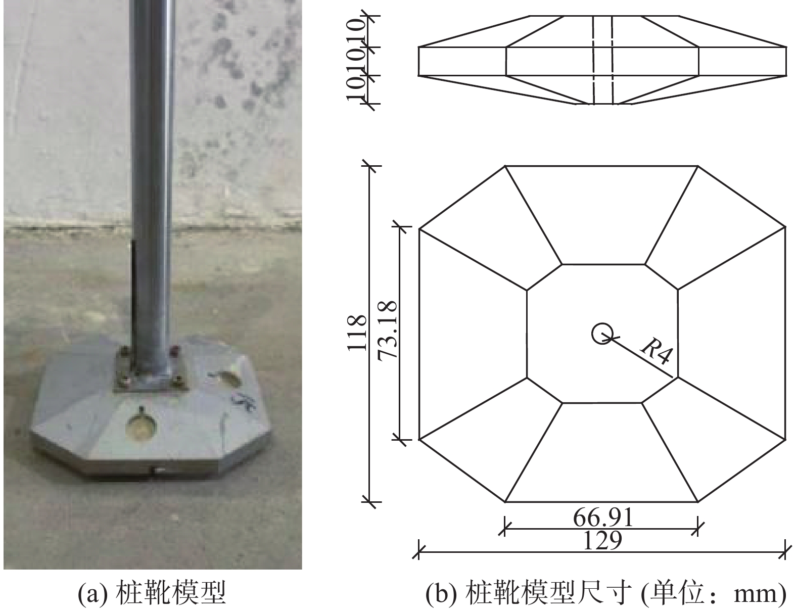
      参数尺寸/mm参数尺寸/mm
      船体型长945桩靴高度30
      船体型宽433桩靴宽度118
      船体型深76桩靴长度129
      桩腿长度867桩靴中心圆孔直径4

      Table 1.  Specific dimensions of the test model of the jack-up installation vessel

      自升式安装船的模型实物如图1所示,为保证每次试验土样达到充分饱和状态,土箱内部设置进排水系统。如图2所示,水流从土体底部灌入渗流而上直到淹没整个土体并达到指定的水深,为减小对土体扰动,进水过程中尽量减小水流速度。图3为桩靴结构示意图,图3(a)为桩靴实物模型图,图3(b)为桩靴的尺寸示意图。

      Figure 1.  Test model of jack-up installation vessel

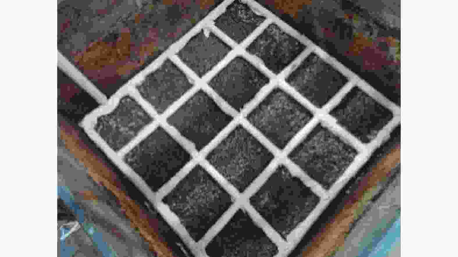
      Figure 2.  Water inlet and drainage system inside the soil box

      Figure 3.  Schematic diagram of spudcan structure

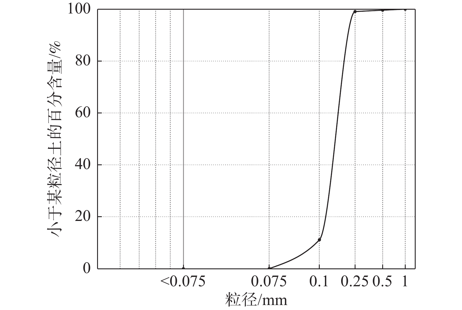
    • 本次试验采用福建标准砂,通过一系列室内土工试验得到基本砂土参数,如表2所示,颗粒级配曲线如图4所示。

      参数数值
      相对密实度 0.58
      弹性模量/MPa 18
      粘聚力/kPa 13.2
      内摩擦角/(°) 32.5
      最大干密度/[g·(cm)−3] 1.50
      最小干密度/[g·(cm)−3] 1.28
      比重/% 2.42
      渗透系数/(cm·s−1) 0.039

      Table 2.  Parameters of the sandy soil

      Figure 4.  Gradation curve of sandy soil particles

      筛分试验采用2 mm、1 mm、0.5 mm、0.25 mm、0.1 mm和0.075 mm的细筛对试验砂土开展了筛分试验。将各粒组含量百分比绘成如图4所示级配曲线,通过级配曲线判定该试验用土为砂土。由级配曲线可知,试验砂土D10=0.09 mm,D30=0.15 mm,D60=0.175 mm,通过公式(1)和公式(2)分别计算得到砂土的不均匀系数为1.94,曲率系数为1.43,由此判定试验砂土为级配连续性较好的均质砂土。

      $$ {C_{\rm{u}}} = \dfrac{{{D_{60}}}}{{{D_{10}}}} = \dfrac{{0.175}}{{0.09}} = 1.94 $$ (1)
      $$ {C_{\rm{c}}} = \dfrac{{D_{30}^2}}{{{D_{60}}{D_{10}}}} = \dfrac{{{{0.15}^2}}}{{0.175 \times 0.09}} = 1.43 $$ (2)
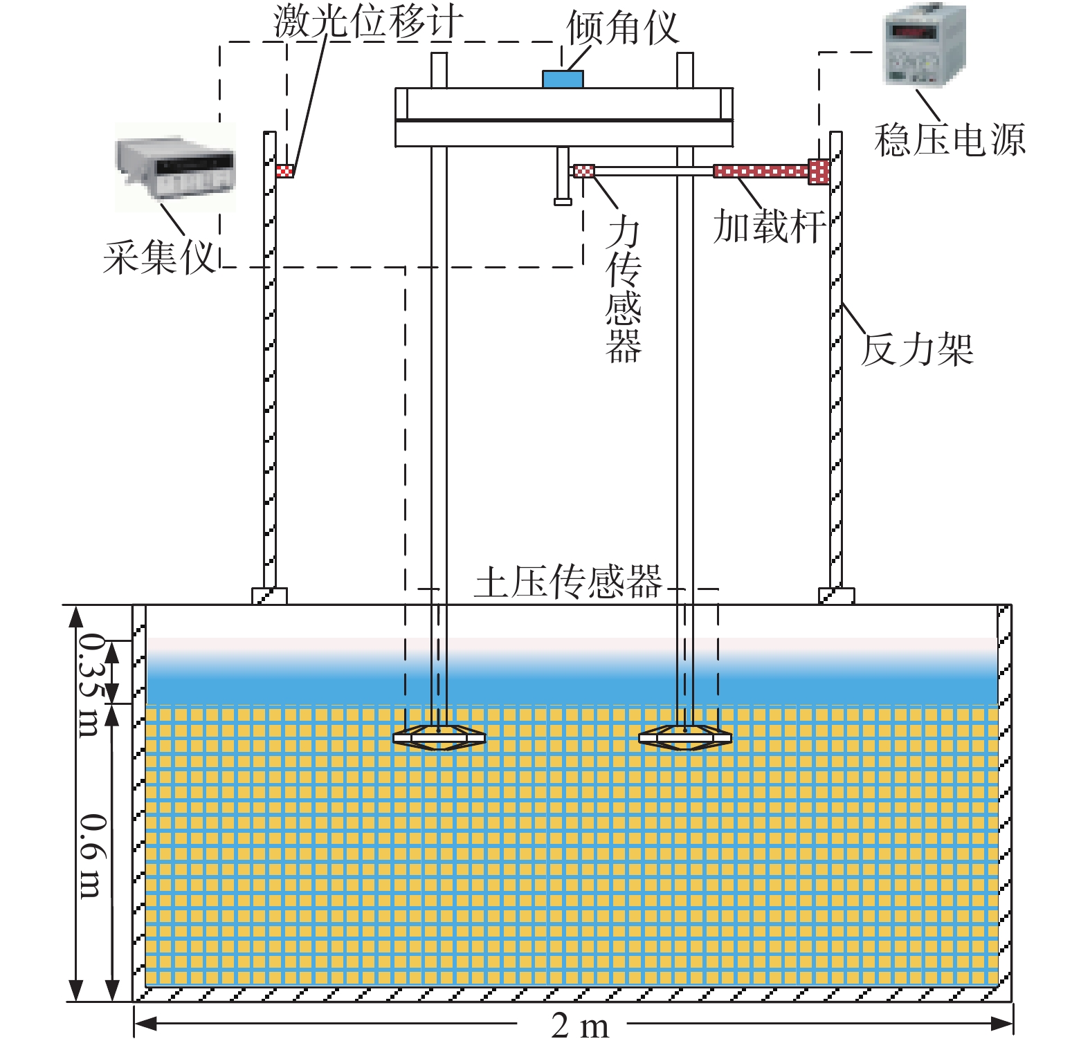
    • 图5为试验加载测量装置布置情况,试验过程通过水平推杆在重心位置施加水平方向的外荷载,直至模型倾覆达到极限状态,在加载过程中,通过船体顶部的倾角仪读数确保各工况下模型的加载角度相同。

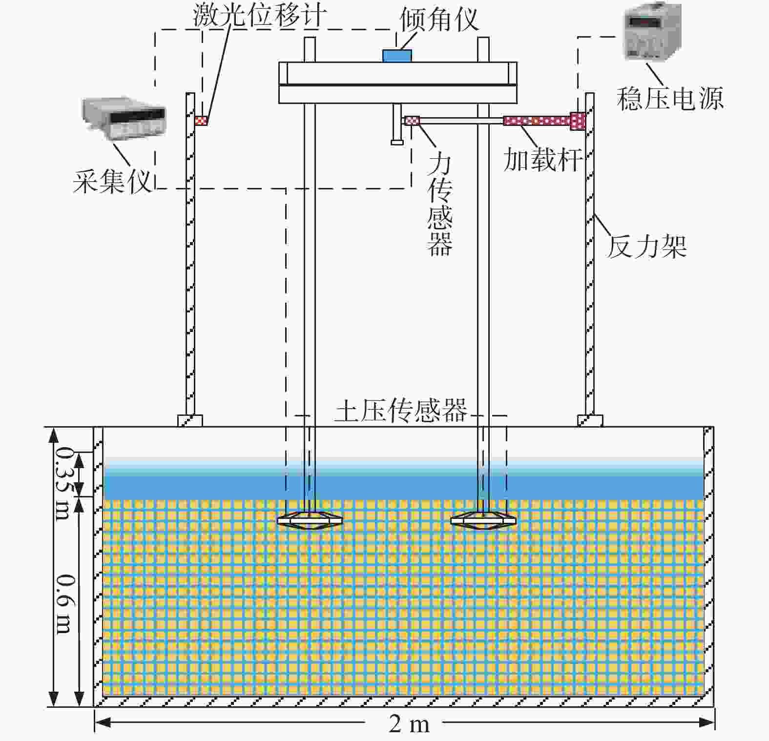
      Figure 5.  Schematic diagram of test loading and measurement device

      采集设备采用威肯德WKD3840应变采集仪,采样频率为10 Hz。用到的传感器主要有:

      1)土压力盒:用于测量桩靴表面不同位置的土压力分布,量程为0~50 kPa。

      2)激光位移传感器:用于测量模型加载过程中的位移,量程为±200 mm。

      3)拉线位移传感器:测量静力触探试验中桩靴的贯入深度,量程为0~500 mm。

      4)倾角仪:用于确认在加载初始阶段自升式安装船的水平度,灵敏度为0.01°。

      5)力传感器:量程0~300 kg,精度0.03%,用于测量加载过程中的水平荷载。

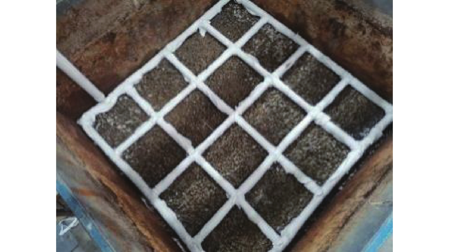
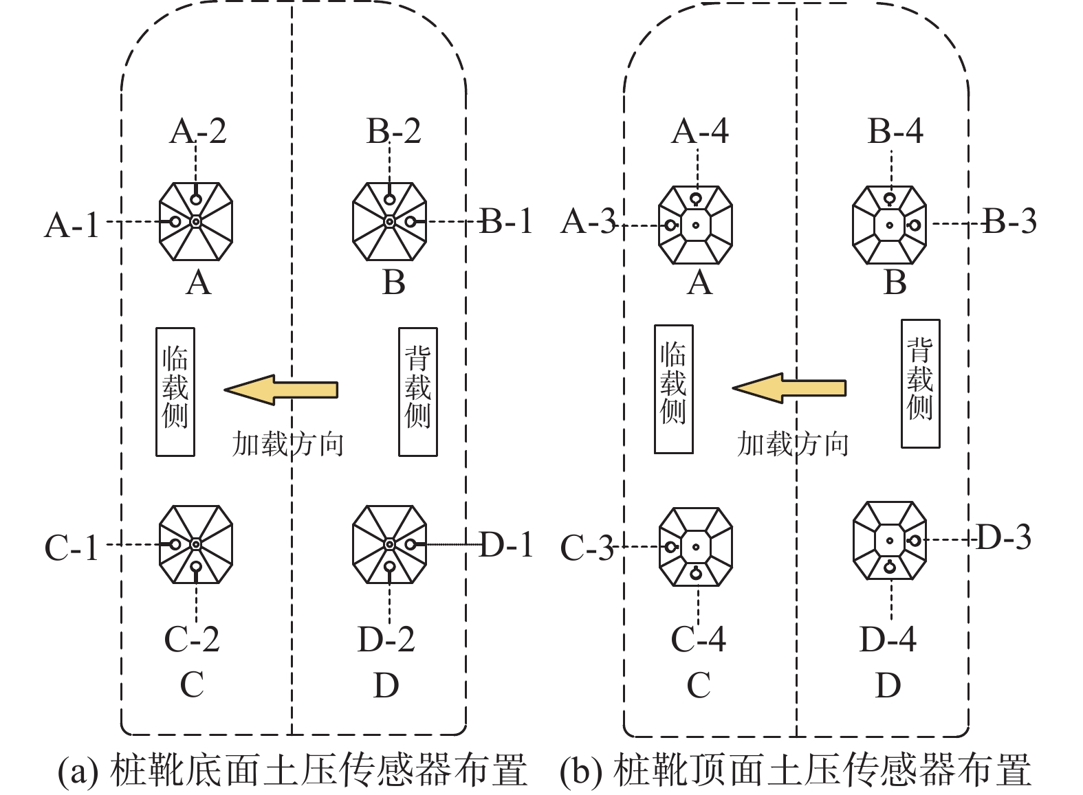
      为监测自升式安装船在水平荷载作用下桩靴周围土压力变化,在桩靴模型表面对称布置了16个土压力盒,具体布置以及测点编号如图6所示,依次将桩靴命名为A、B、C、D号桩靴,其中1号和3号位于同侧,2号和4号位于同侧,每个桩靴上嵌有X-1、X-2、X-3、X-4(X为桩靴编号)4个土压计,其中,X-1和X-2位于底部,X-3和X-4位于顶部。由于自升式安装船具有对称性,文章仅对A号和B号桩靴表面土压力进行对比分析。

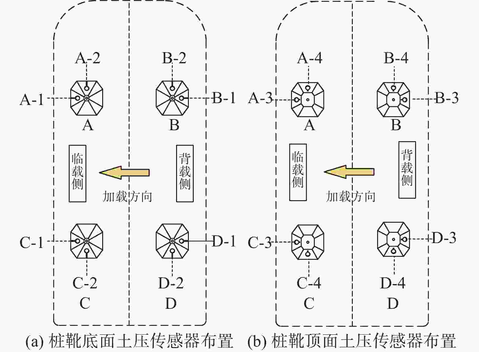
      Figure 6.  Layout of the soil pressure gauge on the spudcan surface

    • 为研究桩靴在不同的贯入深度下自升式安装船的极限水平承载力以及桩靴周围土压力的分布情况,设置了4种不同的贯入深度工况,如表3图7所示。首先进行试验用土制备养护,采用落砂法将砂土均匀地洒落在土槽内,后续试验展开前需要对土槽内的砂土进行翻动,确保每次试验砂土的密实度保持相同。砂土平整后从注水管内向土槽内自下而上注水,使得水从砂土下部逐渐渗透直至越过砂土表面,注水结束后对砂土进行超过24 h的静置养护,得到完全饱和的试验砂土。为了确保每次试验的砂土相对密实度在允许的误差范围内,试验前需要对砂土进行CPT测试。

      工况贯入深度/cm
      14
      26
      38
      410

      Table 3.  Test conditions

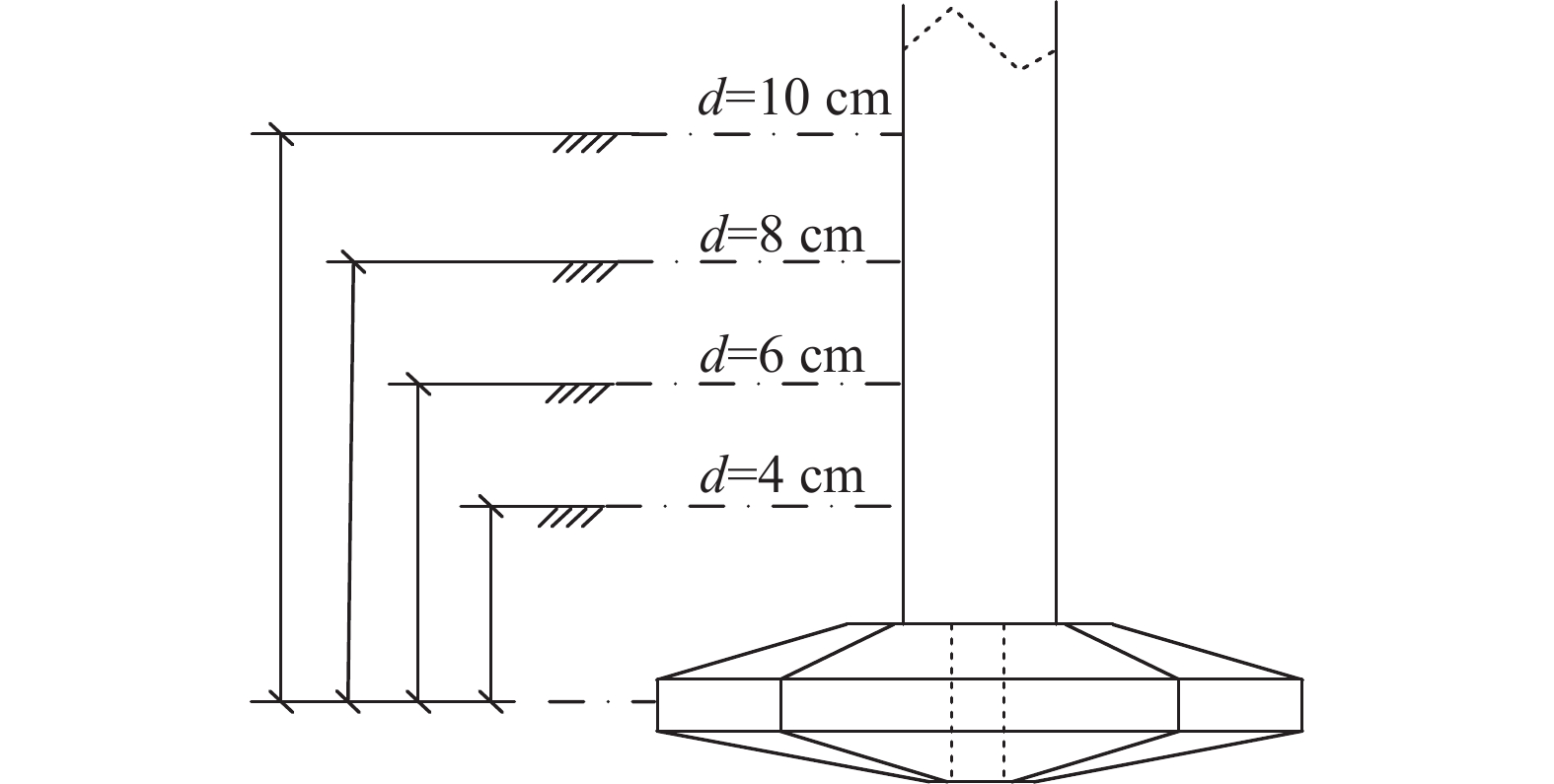
      Figure 7.  Schematic diagram of spudcan penetration depth

      试验过程中通过水平加载杆沿船体横向进行加载,加载速度为0.27 mm/s,加载点设置在模型重心位置,试验过程中监测倾角仪读数,当安装船产生了10°倾角时,模型基本失稳,终止加载。

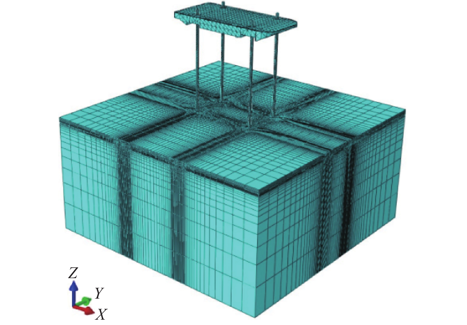
    • 文章采用ABAQUS有限元软件建立自升式安装船的三维有限元模型,如图8所示,模型与试验采取1∶1的比例建立。地基土体采用Mohr-Coulomb本构模型,其参数设置与物理模型试验保持一致。地基土体采用长×宽×高=2 m×2 m×1 m的长方体,可以忽略边界条件对试验的限制,土体底面和侧面分别施加全固定约束和水平约束,设置桩靴与土体的接触时选择刚度大的桩体作为主面、土体作为从面,桩靴与四周土体的接触方式设置为摩擦接触,基础面砂土与桩靴的摩擦系数根据参考值0.25~0.45,选择设定为摩擦系数为0.3。

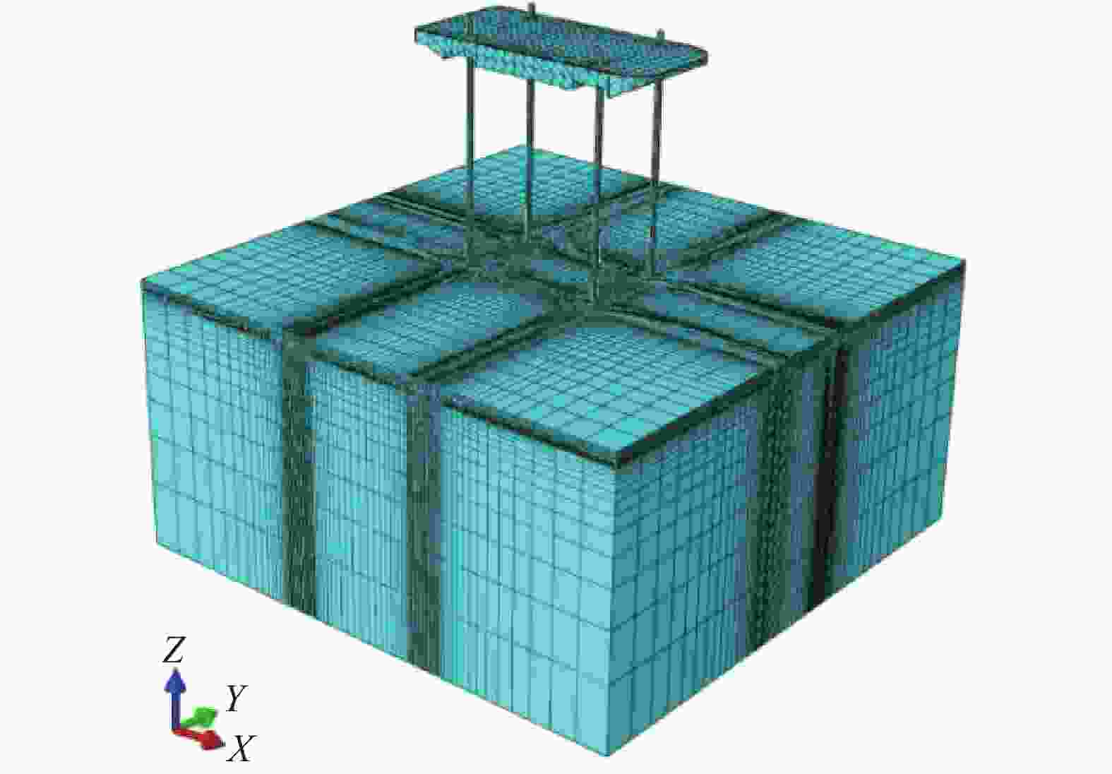
      Figure 8.  Diagram of the calculation model

    • 采用位移控制法来对自升式安装船进行水平加载,加载点与试验相同均位于船体模型下方8 cm处,水平加载直至基础处于极限状态。

      文章参考Villalobos[20]的极限承载力确定方法来计算有限元结果。如图9所示,在位移荷载曲线弹性阶段起点和塑性阶段终点处分别作切线交于一点,然后过交点作1条水平直线与曲线相交于一点,则水平直线与曲线的交点即为基础极限状态对应的点,其对应的荷载即为自升式安装船的极限承载力。

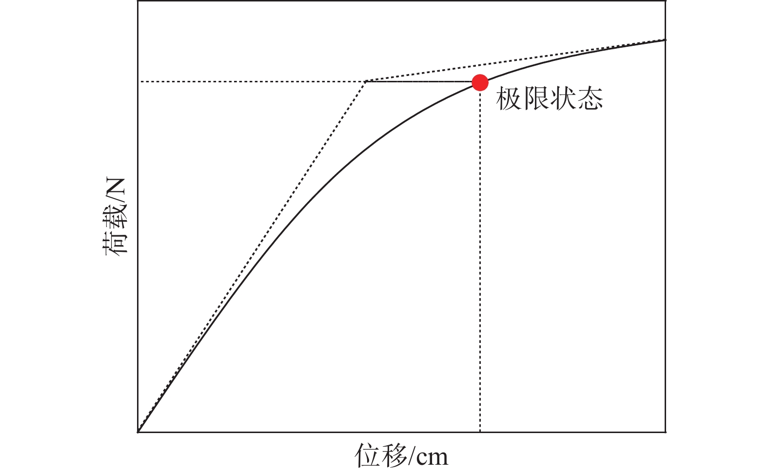
      Figure 9.  Standard for determining the ultimate bearing capacity
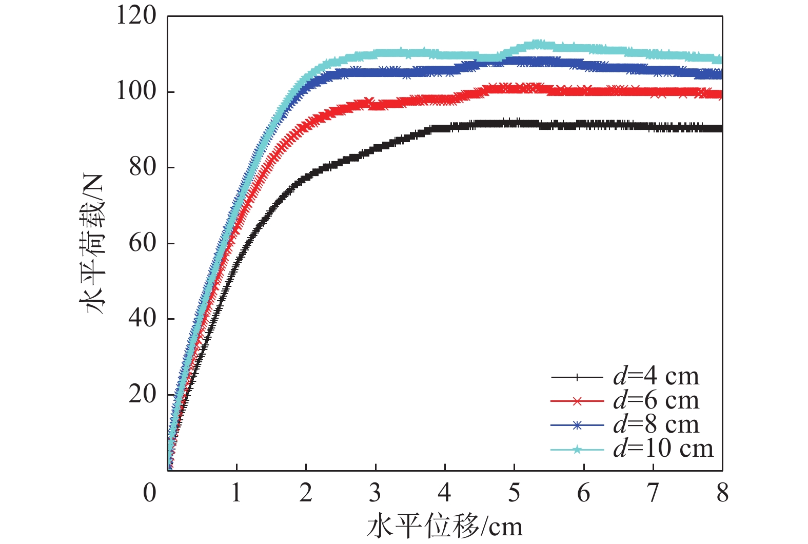
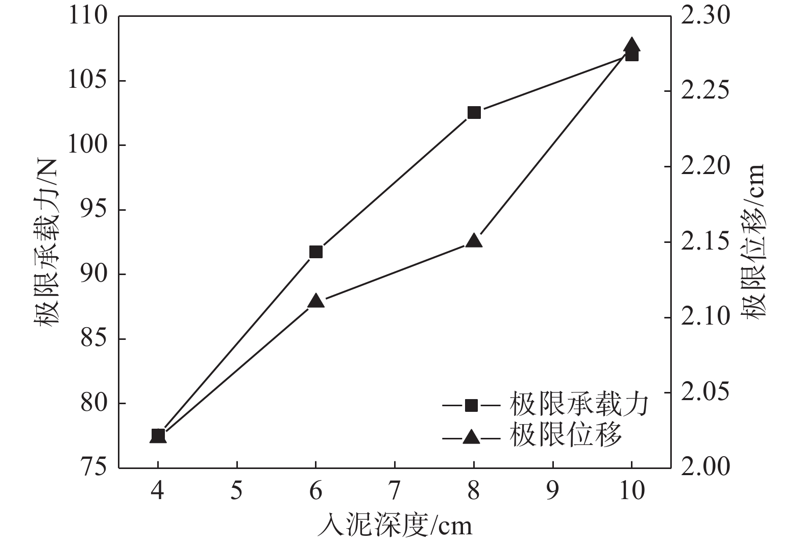
    • 图10为不同贯入深度下的自升式安装船的位移荷载曲线,图11图12分别为不同贯入深度下的极限承载力和极限承载力对应位移的对比结果。由图可知,自升式安装船在砂土中的水平极限承载力随桩靴贯入深度的增大呈增长的趋势,与贯入深度为4 cm相比,贯入深度为6 cm、8 cm、10 cm时的水平极限承载力分别增加18.31%、32.23%、38.02%。极限承载力对应的水平位移同样呈现增加的趋势,当贯入深度为6 cm、8 cm、10 cm时,较贯入深度为4 cm时的水平极限承载力对应的水平位移分别增加4.46%、6.44%和12.87%。

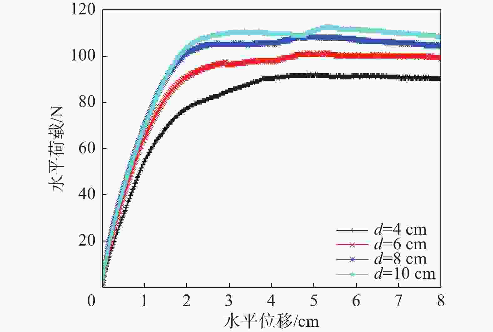
      Figure 10.  Displacement-load curve at different penetration depths

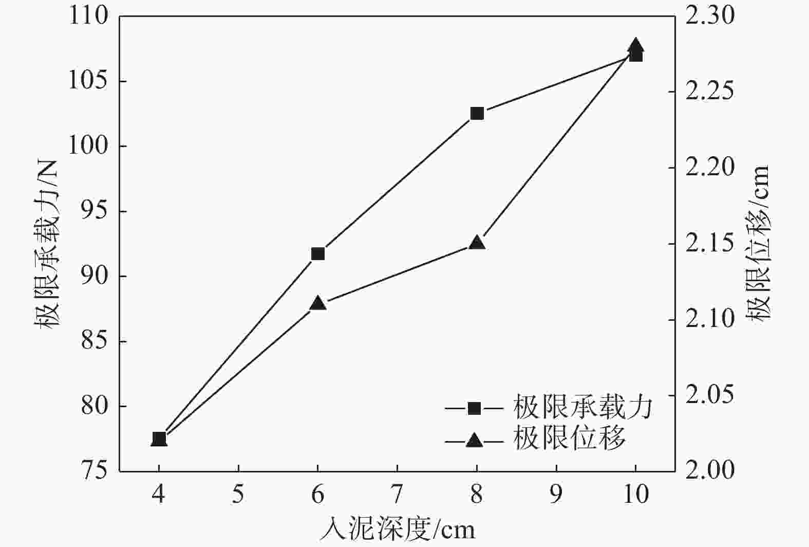
      Figure 11.  Horizontal bearing capacity and its corresponding ultimate displacement at different penetration depths

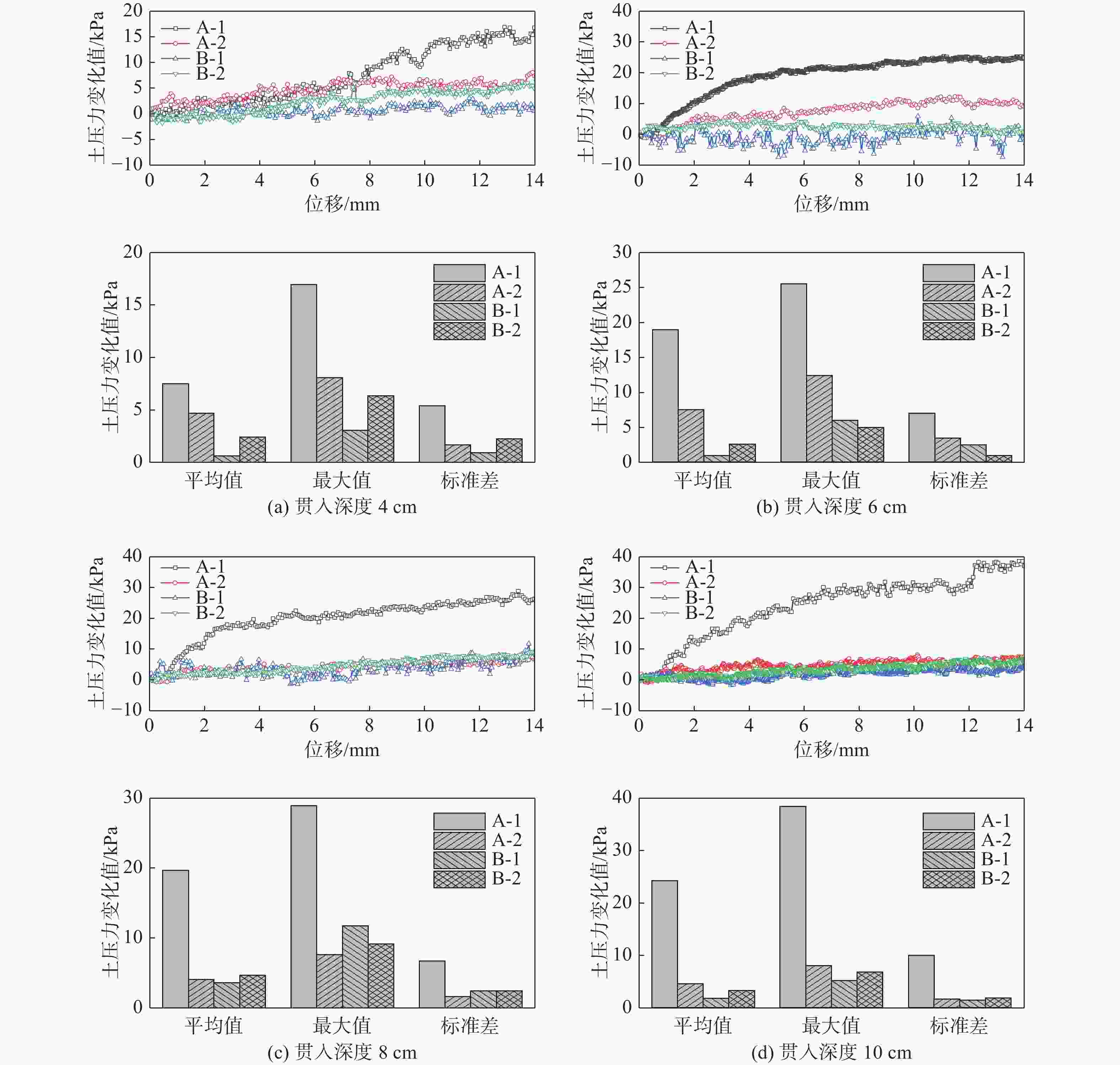
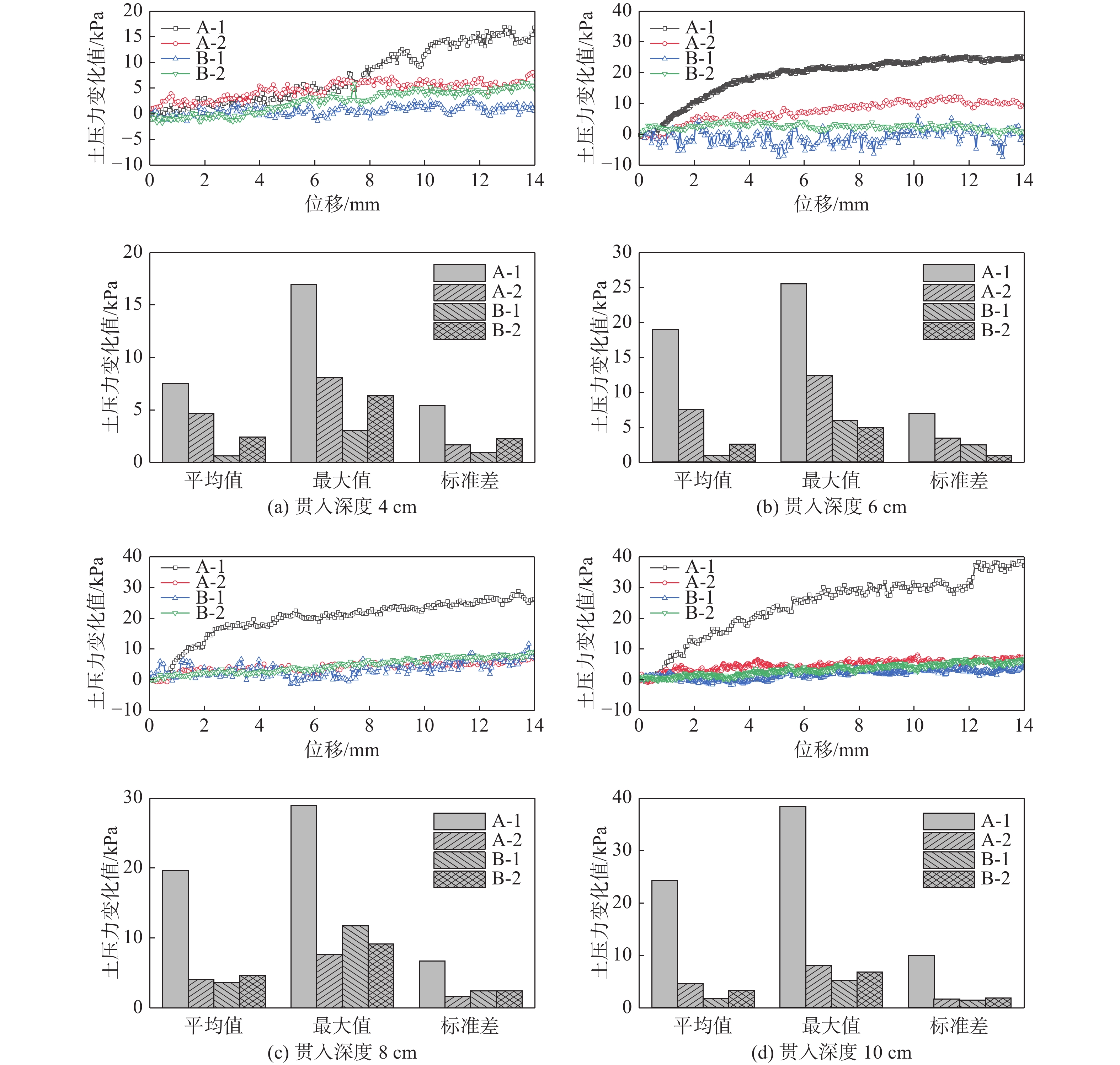
      Figure 12.  Changes of soil pressure around the bottom of the spudcan at different penetration depths

    • 图12为桩靴不同贯入深度下,A和B桩靴底部土压力分布随模型重心水平位移变化的曲线及相应的统计值。其中A-1和A-2测点位于临载侧桩靴A的底部,B-1和B-2测点位于背载侧桩靴B的底部,背载侧桩靴的B-1测点和B-2测点的土压力变化幅值要小于临载侧桩靴A-1和A-2测点。随着水平位移(荷载)的增加,位于临载侧桩靴外边缘A-1测点土压力变化幅值明显大于其他测点,而位于背载侧桩靴外边缘的B-1测点土压力变化幅值最小。

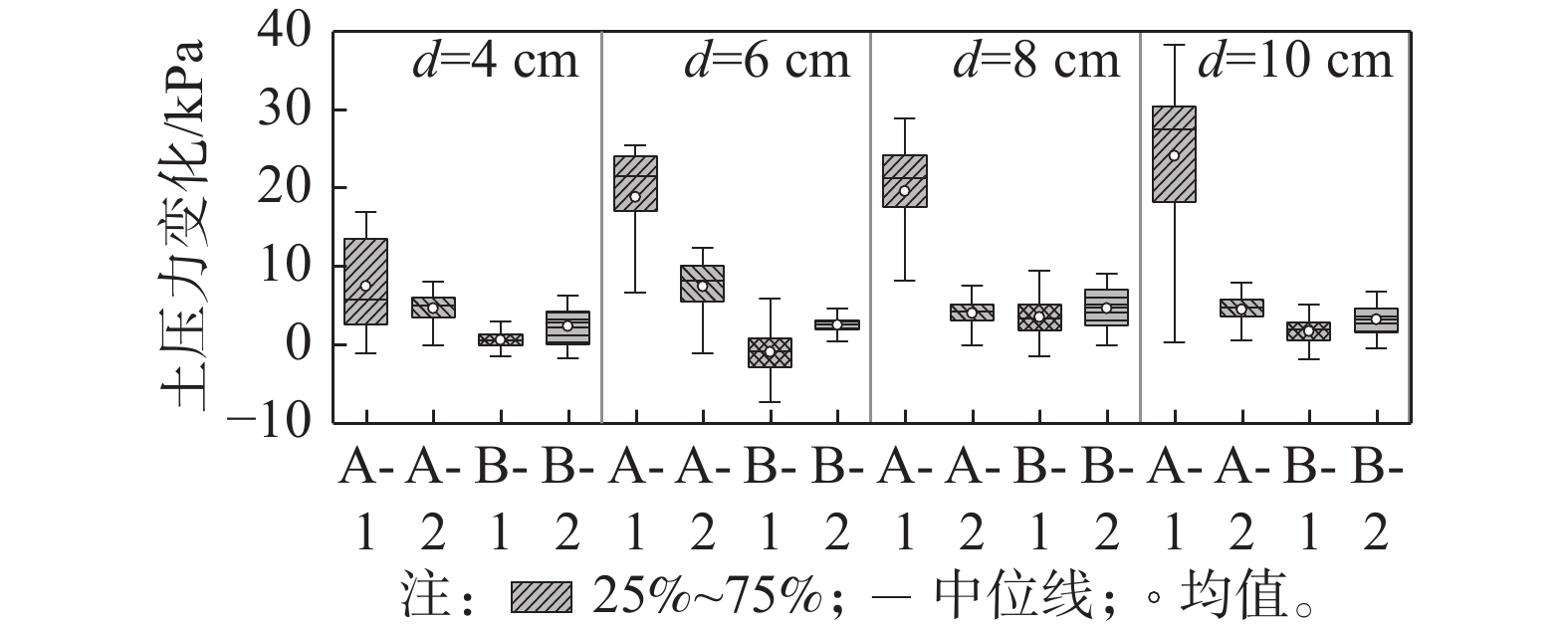
      图13为不同桩靴贯入深度下,A和B桩靴底部各测点的土压力变化对比图。由图可知,A-1测点的土压力变化明显大于其余几个测点,且随着贯入深度的增大,A-1测点土压力变化呈现明显的增大的趋势,其余各测点土压力的变化趋势不明显。当贯入深度为10 cm时,A-1测点的土压力变化最大值为38.37 kPa,较贯入深度为4 cm时增大了126.2%;当贯入深度为4 m时在水平荷载作用下背载侧桩靴B-1和B-2测点土压力均出现了负值,即此时的桩靴B处于受拉状态,桩靴底部和土体出现了大范围的脱开;当贯入深度为6 m时仅B-1测点土压力出现了负值说明此时桩靴B也处于受拉状态,但此时的桩靴底部与土体的脱开面积明显减小。随着贯入深度的增加,测点B-1的土压力基本大于0,桩靴底部与土体尚未发生脱开。

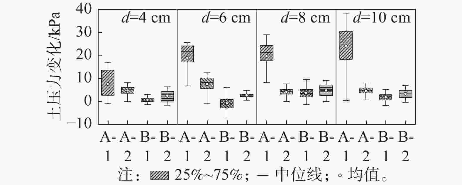
      Figure 13.  Comparison of soil pressure changes around the bottom of the spudcan at different penetration depths

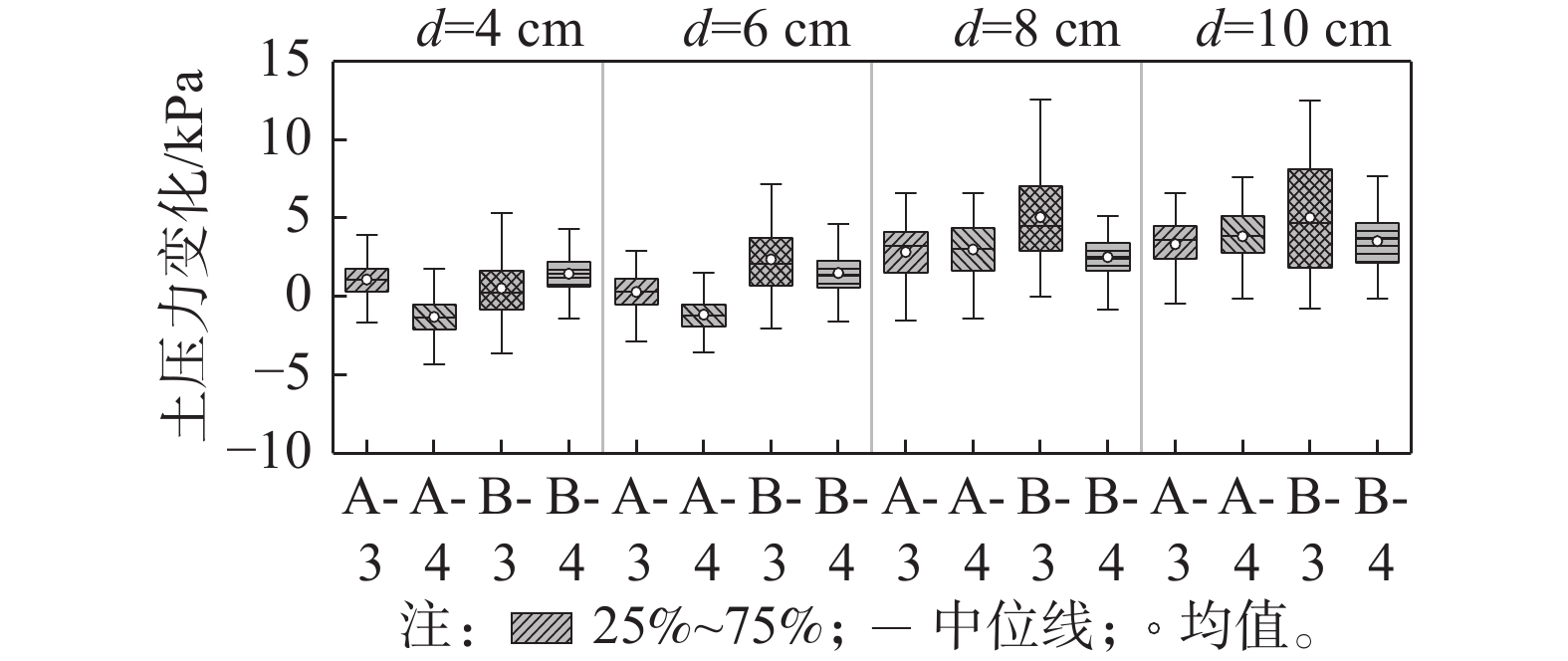
    • 图14为不同贯入深度下桩靴顶面土压力最大值随重心水平位移的变化曲线及其统计结果。其中,A-3和A-4测点位于临载侧桩靴的顶部,B-3和B-4测点位于背载侧桩靴的顶部,在水平荷载的作用下,位于临载侧桩靴上表面的A-3测点和A-4测点所测得的土压力变化值较小,而位于背载侧桩靴顶部的B-3测点和B-4测点所测得的土压力变化略大。当桩靴贯入深度为4 cm时,水平承载力及与其对应的位移较小,桩靴底部各土压力测点的变化值也较小。

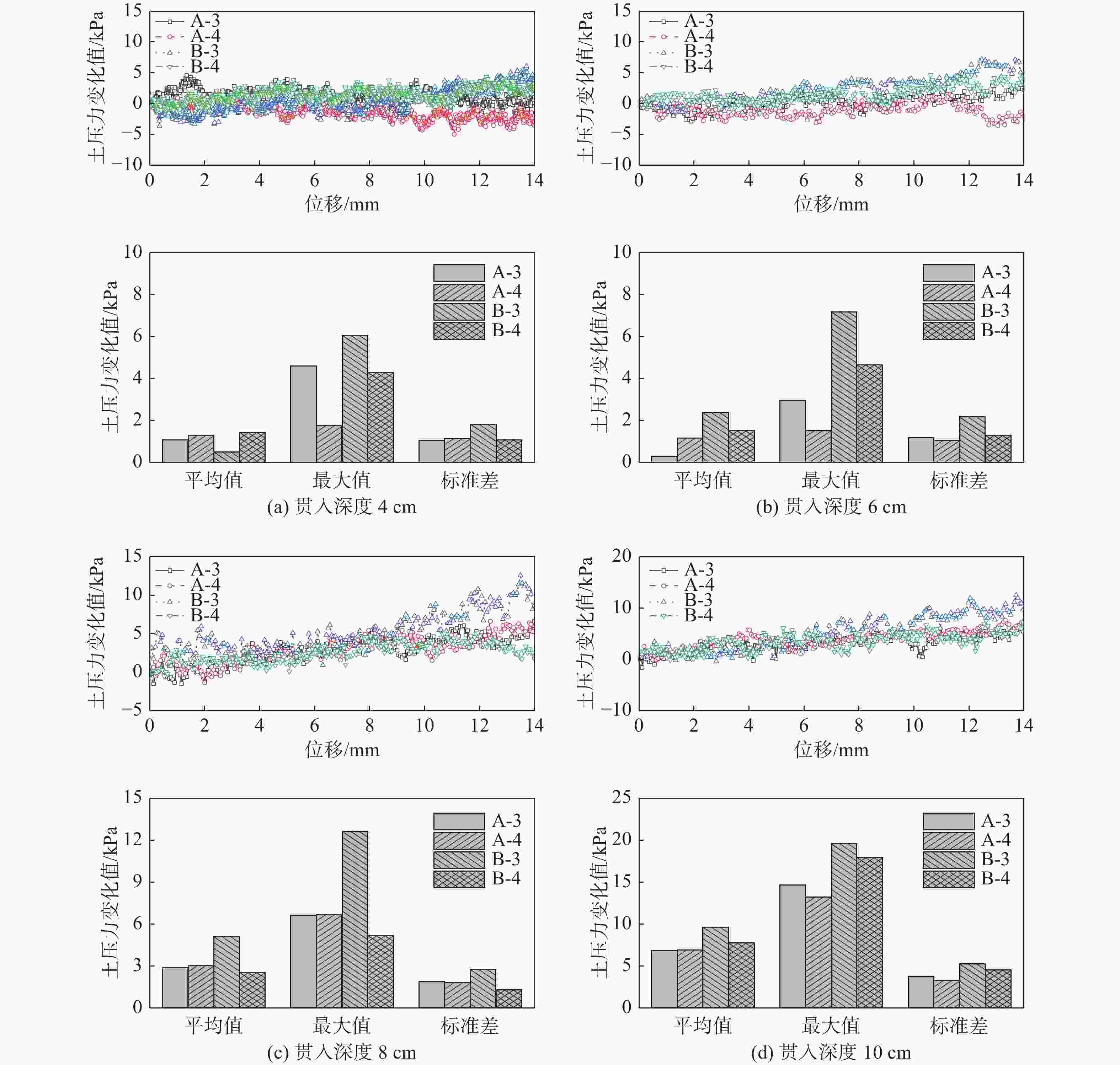
      Figure 14.  Changes of soil pressure around the top of the spudcan at different penetration depths

      图15为不同贯入深度下桩靴顶部土压力变化的对比图。由图可知,在相同工况下,背载侧桩靴上表面的B-3测点所测得的土压力变化值略大于其余测点,且当贯入深度为10 cm时,土压力变化最大值为19.49 kPa,较贯入深度为4 cm时增加221%,贯入深度对临载侧桩靴顶部土压力的影响较大。

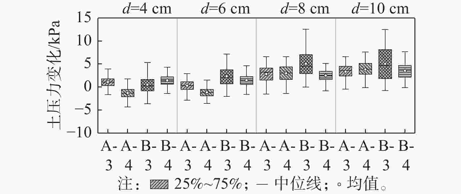
      Figure 15.  Comparison of soil pressure changes around the top of the spudcan at different penetration depths

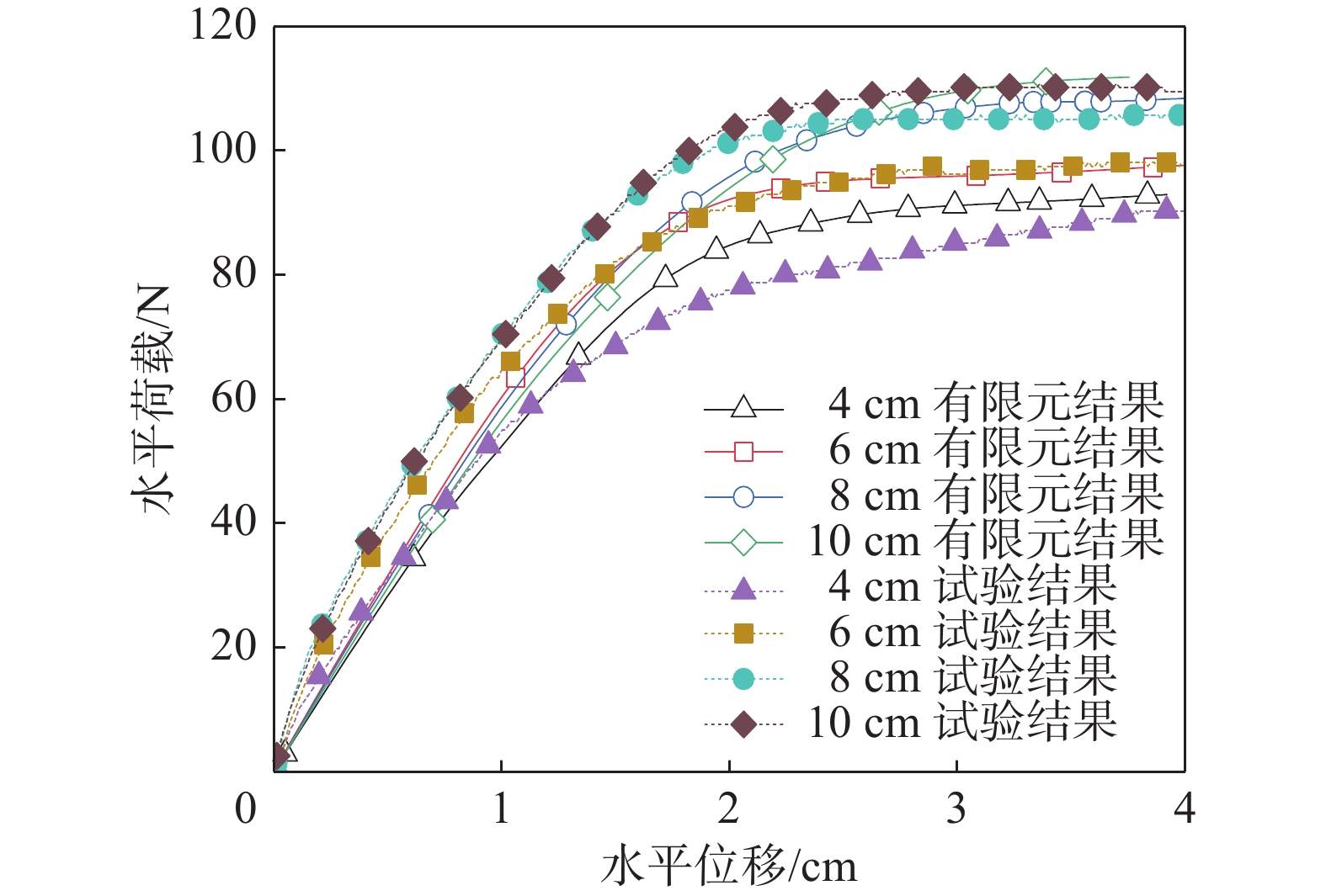
    • 对不同工况的有限元模型进行水平加载后,得到加载点位移与对应的水平荷载的荷载-位移曲线,有限元与试验结果的对比图如图16所示,整体上看二者趋势相近,对于4组不同贯入深度下的水平极限承载力,二者最大误差为6.07%,平均误差为2.70%,通过以上对比可以验证试验结果的可靠性。

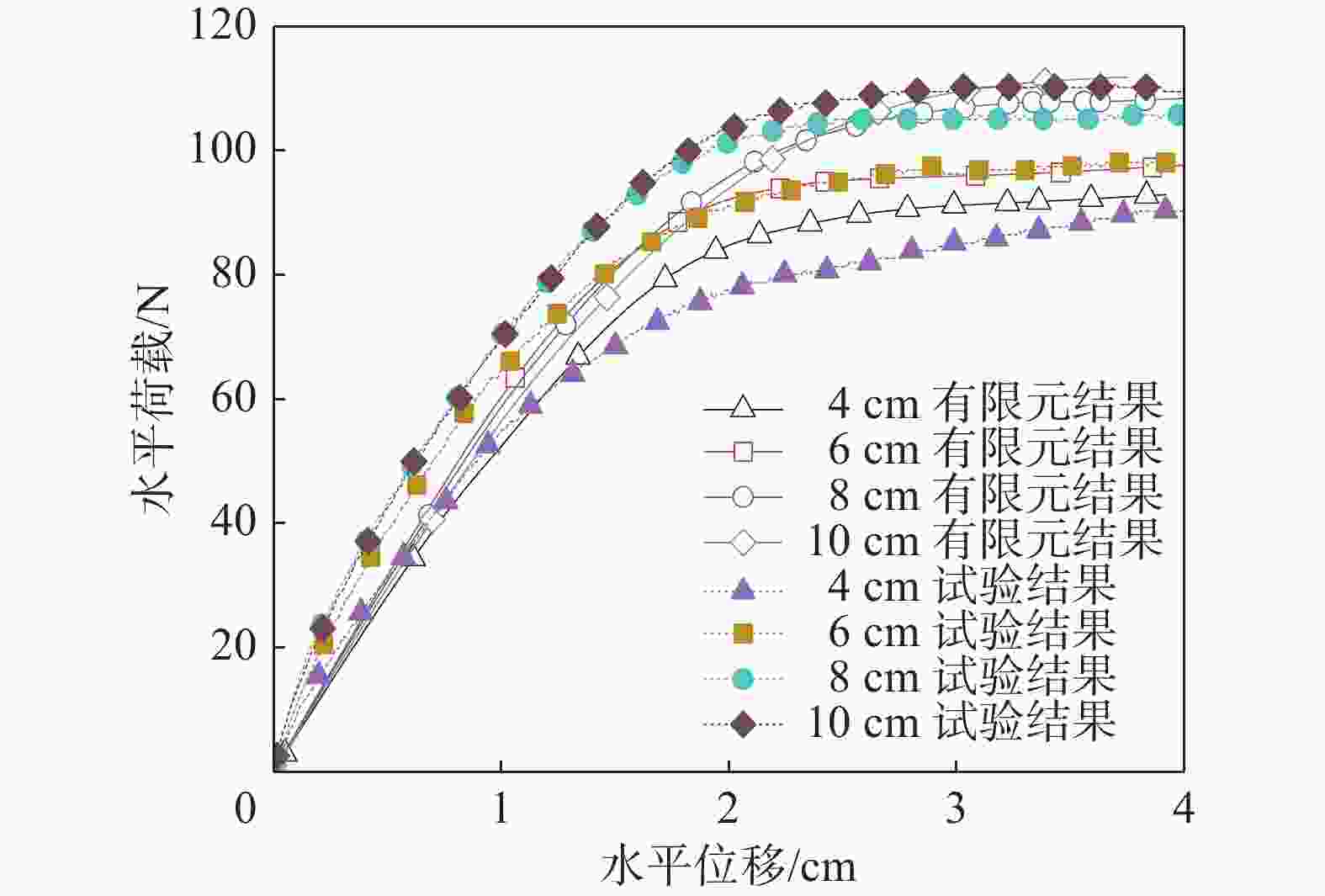
      Figure 16.  Comparison of FE results with physical test results

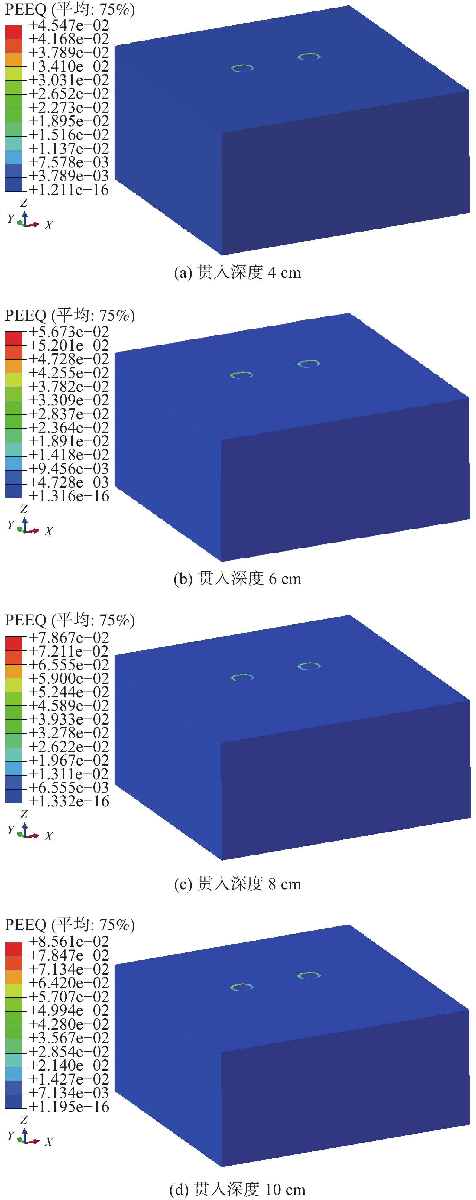
    • 图17为在位移加载方式下不同贯入深度对应的地基土体等效塑性应变云图。由上图可知,不同贯入深度的自升式安装船对地基土体的作用规律类似,桩靴底部土体的形变主要集中在桩靴受压一侧。随着贯入深度的增大,土体的塑性应变逐渐增大,和试验的土压力变化相吻合。

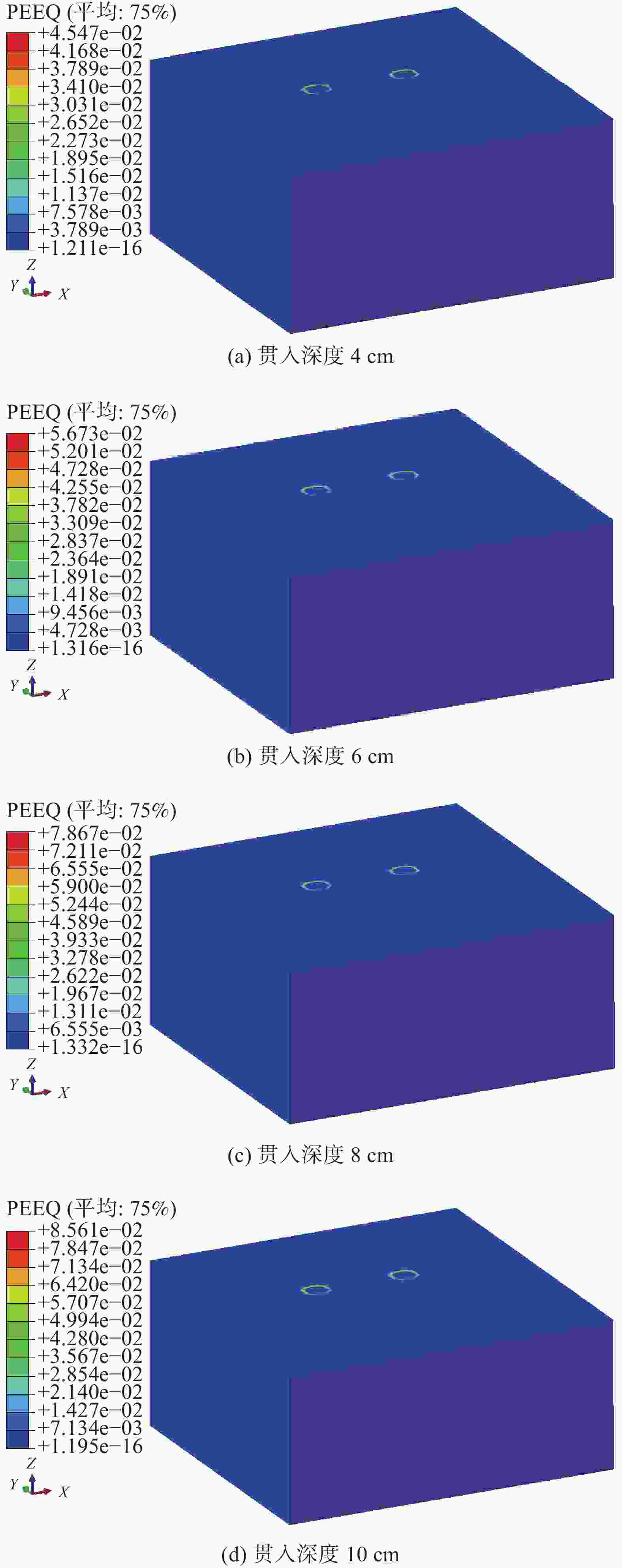
      Figure 17.  Equivalent plastic strain nephogram of foundation soil at different penetration depths

    • 针对自升式安装船在均质砂土中的水平承载力以及荷载作用下的桩靴周围土压力变化情况开展了土槽试验,探讨了桩靴不同的贯入深度对基础承载力的影响规律,并分析了桩靴上、下表面周围土压力分布以及变化规律,得到主要结论如下:

      1)自升式安装船的水平承载力随着贯入深度的增加呈现增加的趋势,贯入深度为10 cm较贯入深度为4 cm时的水平承载力增加38.02%;当贯入深度为6 cm、8 cm、10 cm时,较贯入深度为4 cm时的水平极限承载力对应的水平位移分别为增加4.46%、6.44%和12.87%。

      2)随着贯入深度的增大,桩靴各测点所测得的土压变化的最大值呈现增大的趋势。当贯入深度为10 cm时,临载侧桩靴底部A-1测点的土压力变化最大值为38.37 kPa,较贯入深度为4 cm时增大了126.2%;相同工况下,位于临载侧桩靴底部外边缘的土压力变化值更大,且试验过程中土压力变化范围在0~50 kPa之间。从土压力变化情况可知,自升式安装船在水平荷载作用下,其承载模式表现为临载侧桩靴受压,背载侧桩靴受拉。当贯入深度较浅时,背载侧桩靴与底部土体发生脱开,但随着贯入深度的增加,其脱开面积逐渐减小。

Reference (20)

Catalog

    /

    DownLoad:  Full-Size Img  PowerPoint
    Return
    Return