

-
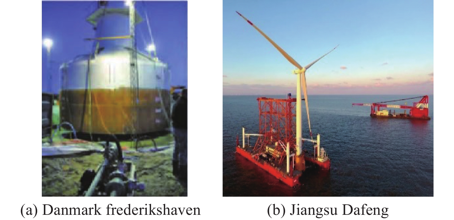
With the increasing popularity of the offshore wind power industry, wind turbine foundations have received more and more attention. Among the various designs, the bucket foundation occupies a certain market because of its advantages of simple structure, low cost and convenient installation. In addition to the traditional mono bucket foundation (MBF), such as bucket foundation in Danmark Frederikshaven wind farm (2003) shown in Fig. 1(a), the emerging composite bucket foundation (CBF) and multi-bucket foundation are also favored in recent years. The CBF is a large-scale wide shallow foundation structure. The whole structure effectively transforms the huge bending moment of the tubular tower into the limited tension and compression stress of the foundation structure through the prestressed concrete arc transition section[1]. The honeycomb structure inside the bucket equips the CBF with good floating stability and can realize towing transport[2-3]. In addition, the suction of each chamber can be adjusted independently, thus, the foundation meets the requirements of precise leveling during installation. The installation of composite bucket foundation for Jiangsu Dafeng 300 MW offshore wind turbine project in 2018 is shown in Fig. 1(b).
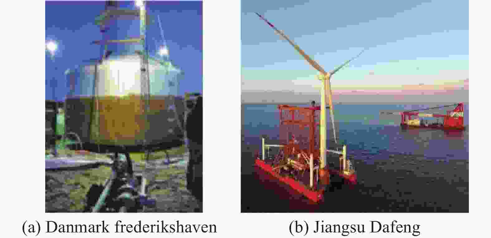
Figure 1. Mono bucket foundation and composite bucket foundation
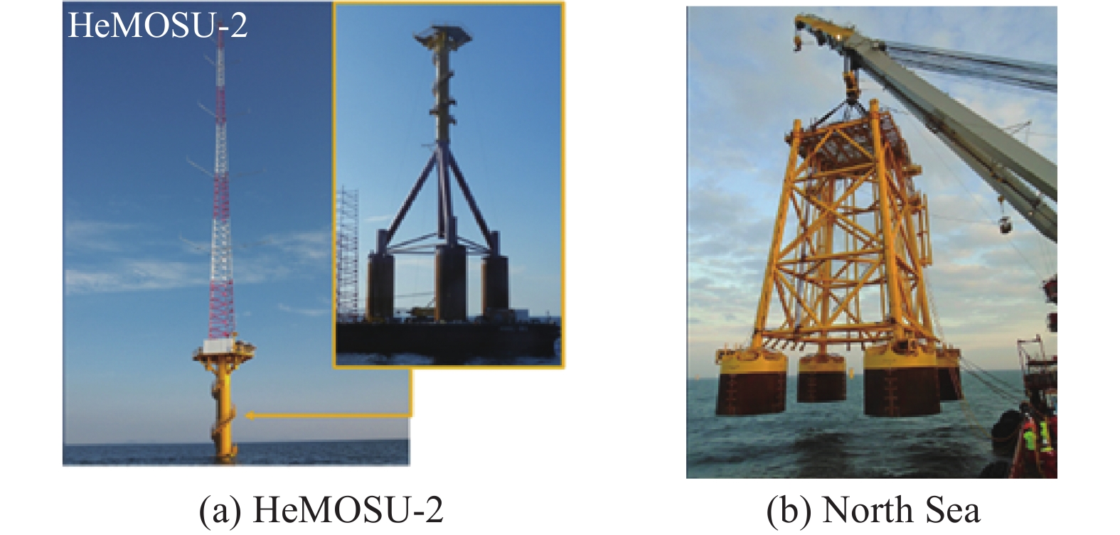
As multi-bucket foundations have the additional advantages of dispersing the load and improving the anti-roll capability, research into their application has received more attention. In 2011, the Korea Electric Power Company's HeMOSU-2 was successfully installed and operated using a three-bucket jacket foundation, as shown in Fig. 2(a). In 2016, the installation of a four-bucket jacket foundation for offshore wind turbine (OWT) was carried out in the North Sea area of the United Kingdom, as shown in Fig. 2(b). The results confirm the feasibility and economy of the jacket structure using a multi-bucket foundation[4-5].
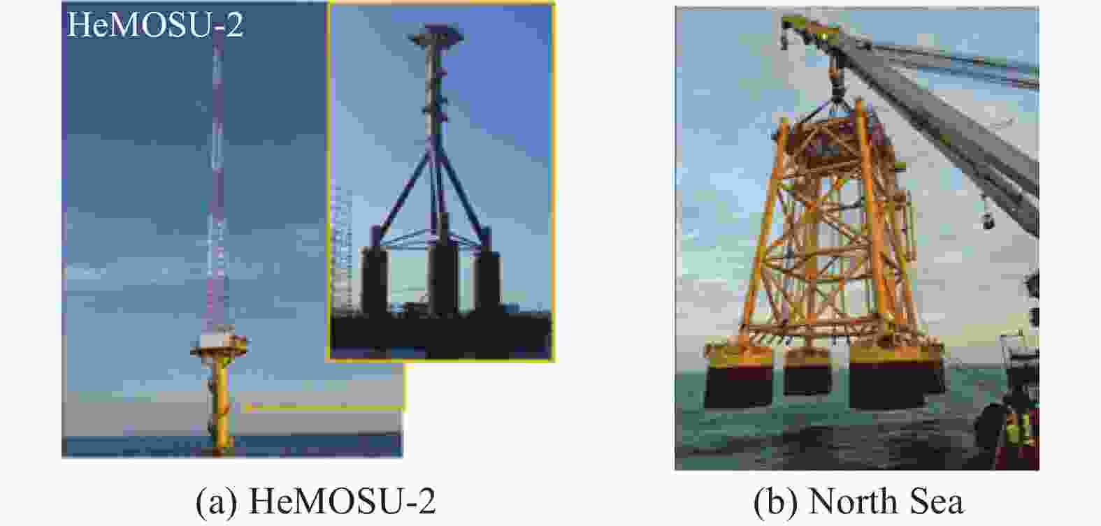
Figure 2. Multi-bucket jacket foundations for OWTs
With regard to the dynamic characteristics of bucket foundations, many scholars have studied it via tests and numerical simulations. Wang X F et al.[6] designed five types of suction bucket foundations with different bucket diameters, buried depths, and internal subdivisions. Nine groups of centrifugal tests were conducted, and the seismic response of these foundations were studied in both dry soil and saturated soil. The liquefaction region of soil for bucket foundations subjected to seismic load was studied by Ding H Y et al.[7] With the help of the finite element software ADINA, their study focused on the development laws of effective stress, pore water pressure, and excess pore pressure of the soil inside and around the foundation. Moreover, the influence of seismic intensity on the liquefaction characteristics of foundation soil and the settlement of the soil surrounding the bucket were considered. The anti-liquefaction shear stress method proposed by Seed H B was adopted, and the soil liquefaction of a bucket foundation under seismic load was calculated and assessed by Zhang P Y et al.[8]. The liquefaction degree of the bucket foundation during an earthquake was calculated by Li F[9], and whether the bucket foundation structure can continue to bear load after soil liquefaction was judged. A quasi-static model test of the bucket foundation (mono bucket and four bucket foundation) as wind turbine foundation under cyclic load was conducted by Houlsby G T et al.[10-11]. They tested the bearing capacity of bucket foundations on clay and sandy soil under cyclic load, and presented the structural dynamic response and foundation stiffness variation rules. The 3-dimensional FE method was used to investigate the seismic response of suction bucket foundations by Saleh et al.[12]. Their results were in good agreement with their centrifuge results. Their simulation also indicated that the sandy soil outside the caisson is prone to liquefaction due to its lack of confinement.
The seismic response of tripod jacket foundations was investigated using fully coupled nonlinear time-domain simulations by Alati et al.[13]. Their results indicated that earthquake loading can lead to a great increase in the resulting structural stresses. A fully-coupled 3D nonlinear numerical model was developed and the results were compared with results from the centrifuge experiments for a shallow-coupled structure on liquefiable sand by Karimi Z et al.[14].
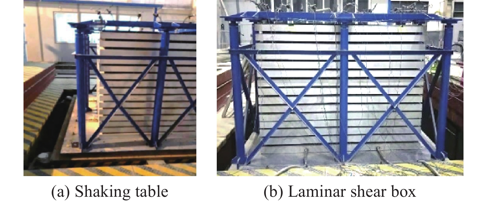
The behavior of wind turbine jacket foundations subjected to seismic loading was investigated by Ku C Y et al.[15]. Zhang J H et al.[16] performed a series of centrifuge tests on suction foundations for OWTs under static and cyclic loadings to investigate dynamic responses. A design for a bucket foundation structure considering earthquake loads was carried out by Zhang P Y et al.[17] and Ding H Y et al.[18] An analysis of the liquefying areas near the bucket foundation due to earthquakes was performed using the FE software ADINA. Centrifuge shake table tests were carried out by Wang X F et al.[19] to study the seismic performance of hybrid monopile foundations, shaking table and laminar shear box is shown in Fig. 3.
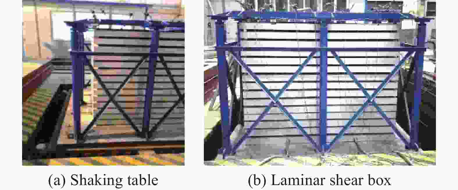
Figure 3. Shaking table and laminar shear box
The seismic bearing mechanism of bucket foundation in clay was investigated, and various factors affecting seismic responses of suction bucket were analyzed by Zhang J X et al.[20]. Sadowski et al.[21] analyzed the SSI effect of the foundation for offshore wind turbine, and it is found that the soil acceleration obviously affect the bearing performance of soil, as well as the frequency and working performance of the structure. A series of attempts on the seismic response of offshore wind turbine foundation were made by Katsanos et al.[22] and suggestions on the optimal design of the foundation structure were given. The dynamic centrifuge tests for a bucket foundation and an additional gravity foundation models installed in sandy soil were carried out by Olalo et al.[23], and then seismic response of bucket foundations was investigated[24-25].
-
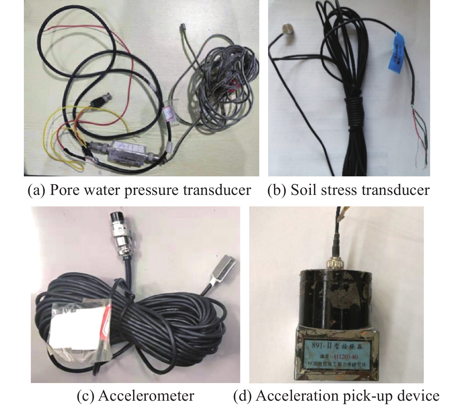
Since the subject of this study is the seismic response of sandy soil of four bucket jacket foundation, four types of sensors are used in the test, including pore pressure sensor, soil stress transducer, accelerometer and acceleration pick-up device, as shown in Fig. 4. The pore pressure sensor and soil stress transducer are used to obtain pore pressure initial stress of soil, accelerometer and acceleration pick-up device are used to collect acceleration response of foundation soil and shaking table, respectively.
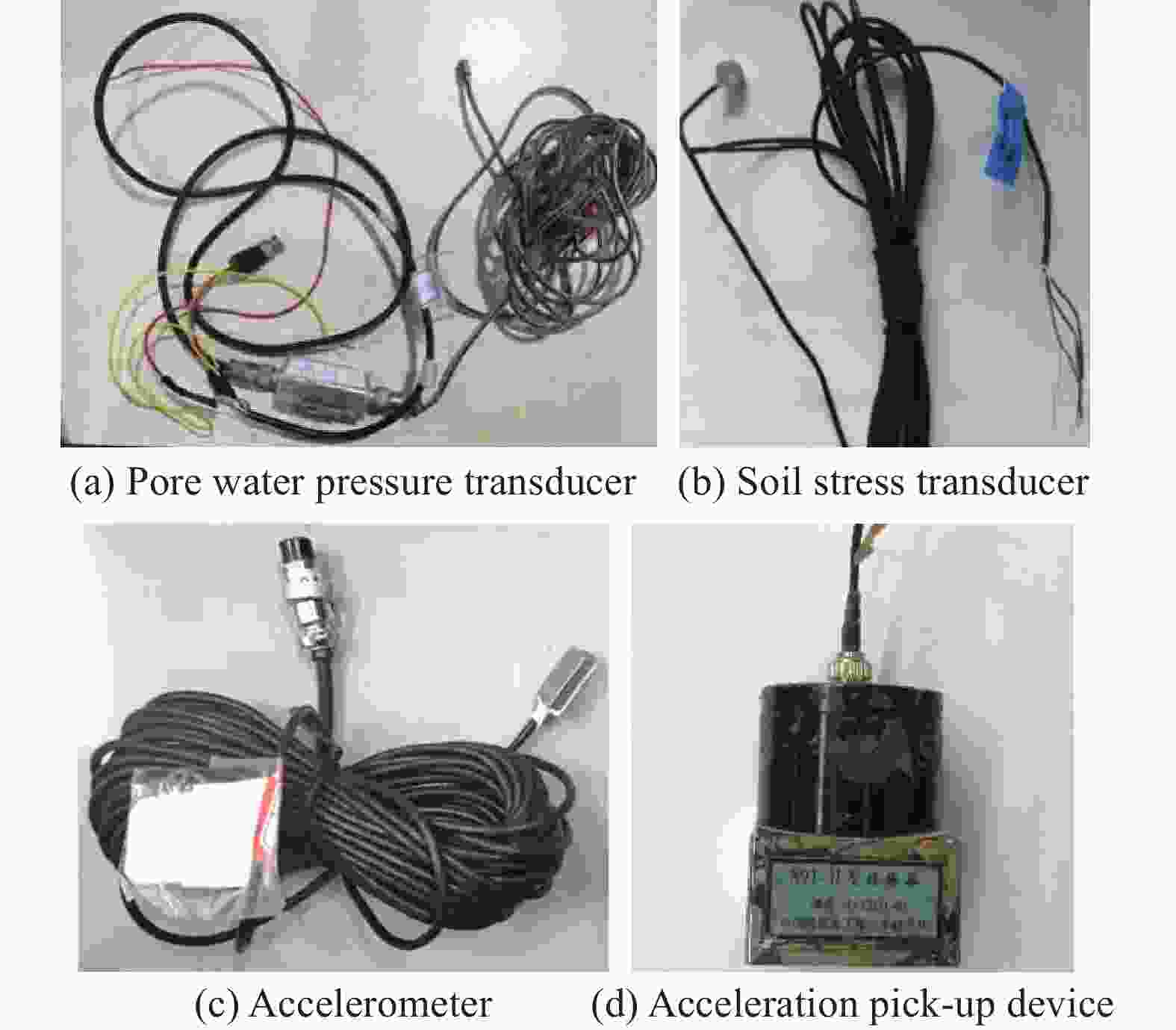
Figure 4. Sensors used in shaking table test
EI-Centro wave is adopted as the input seismic wave, which is a group of Seismic wave data measured by the United States in 1940. According to GB 50011-2010 Code for Seismic Design of Buildings[26], four groups of process (EI1, EI2, EI3 and EI4) were carried out, corresponding to the peak acceleration of 0.1 g, 0.175 g, 0.22 g and 0.4 g respectively. Table 1 shows the test conditions.
Process Input waves Acceleration
peak value/gCorresponding seismic intensity EI1 EI-Centro 0.100 Fortification earthquake of 7 degree EI2 EI-Centro 0.175 Added condition EI3 EI-Centro 0.220 Fortification earthquake of 8 degree EI4 EI-Centro 0.400 Fortification earthquake of 9 degree Table 1. Test conditions
The test models are designed referred to the prototype. The length similarity ratio adopts
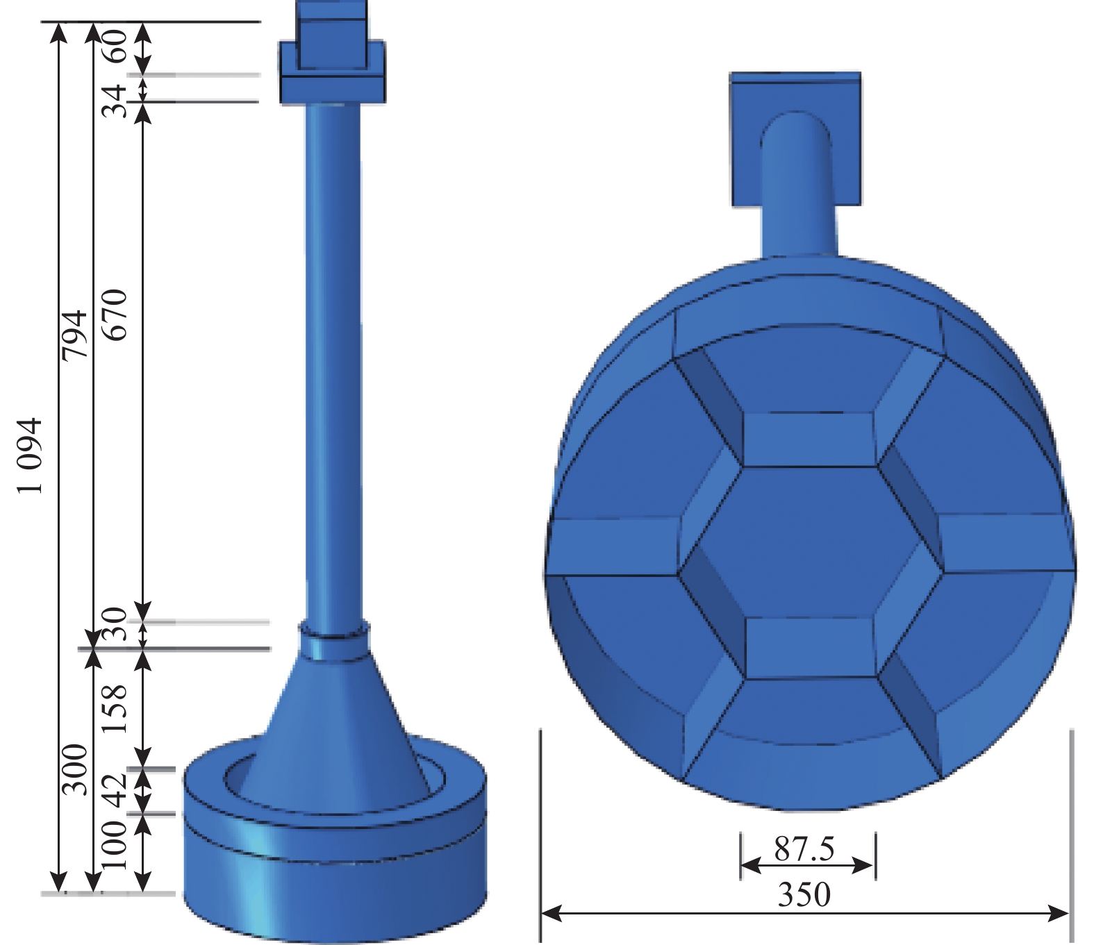
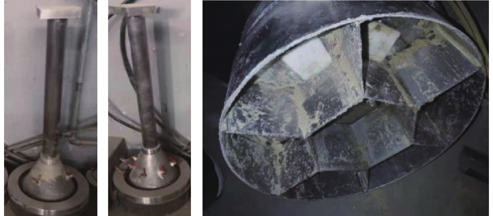
${S_{\rm{L}}} = \dfrac{1}{{100}}$ , the mass similarity ratio is${S_{\rm{m}}} = \dfrac{1}{{50\;000}}$ , and partial counterweight is designed to satisfy the similarity ratio criterion.The test models of mono-bucket foundation and composite bucket foundation have the same parameters such as bucket height, bucket diameter, transition section height and tower tube height, except for the difference of compartments inside the bucket. The composite bucket foundation has seven compartments inside the bucket, while the mono-bucket foundation has no compartment inside the bucket. Stainless-steel counterweight is welded at corresponding positions, as shown in Fig. 5 and Fig. 6.
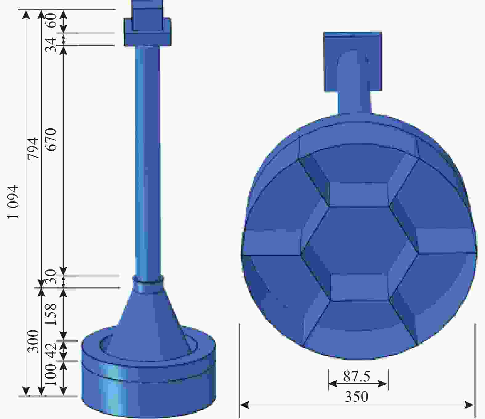
Figure 5. Dimensions of MBF and CBF
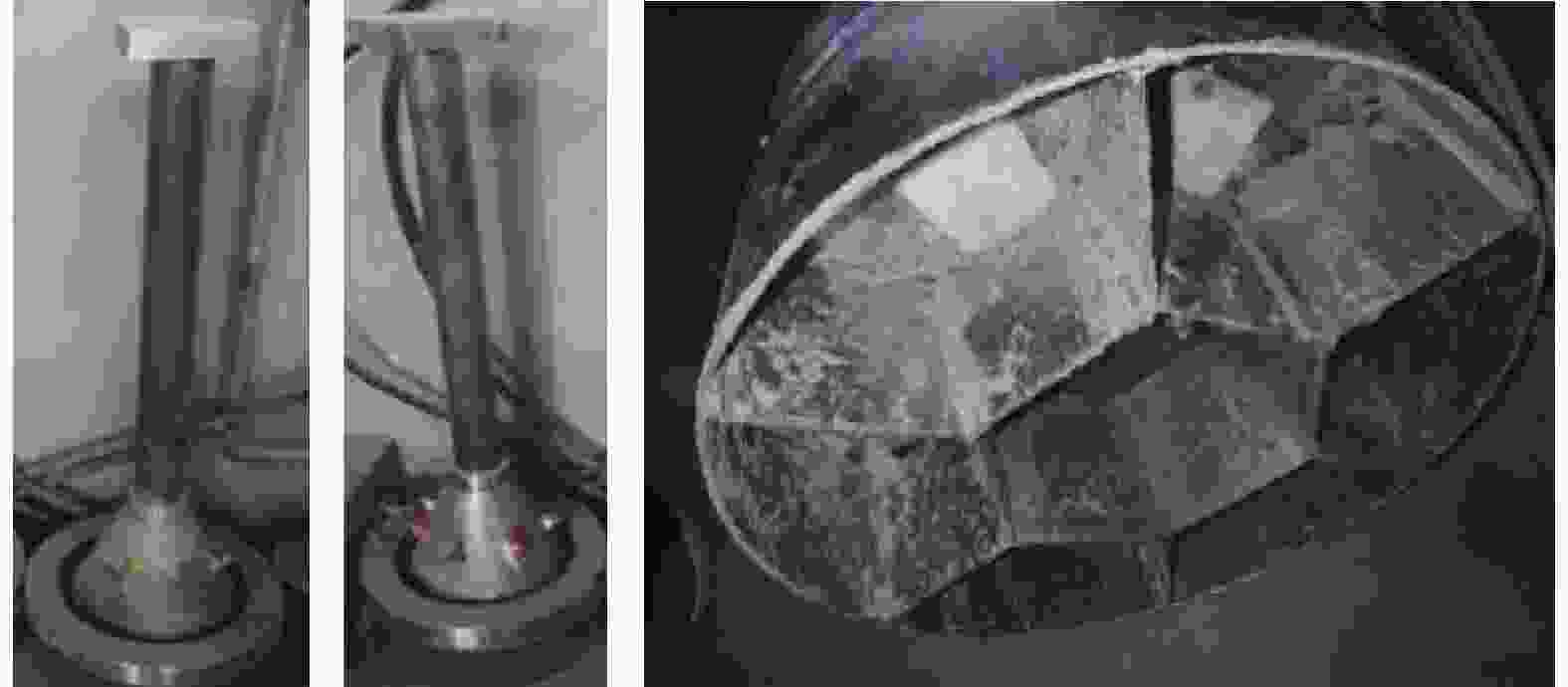
Figure 6. Physical pictures of MBF and CBF
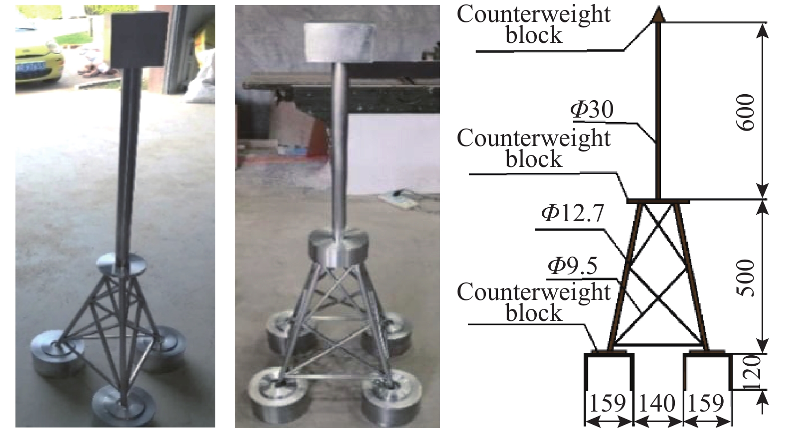
Similarly, for the convenience of comparison, the parameters of bucket height, bucket diameter, transition section height and tower tube height for three-bucket jacket and four-bucket jacket foundation are the same, and stainless-steel counterweight blocks are welded at corresponding positions, as shown in Fig. 7.
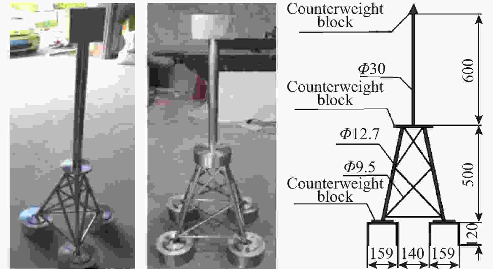
Figure 7. Test models of TBJF and FBJF
-
The test phenomena of mono-bucket and composite bucket foundation, three-bucket jacket and four-bucket jacket foundation are compared respectively.
1) Phenomena of MBF and CBF
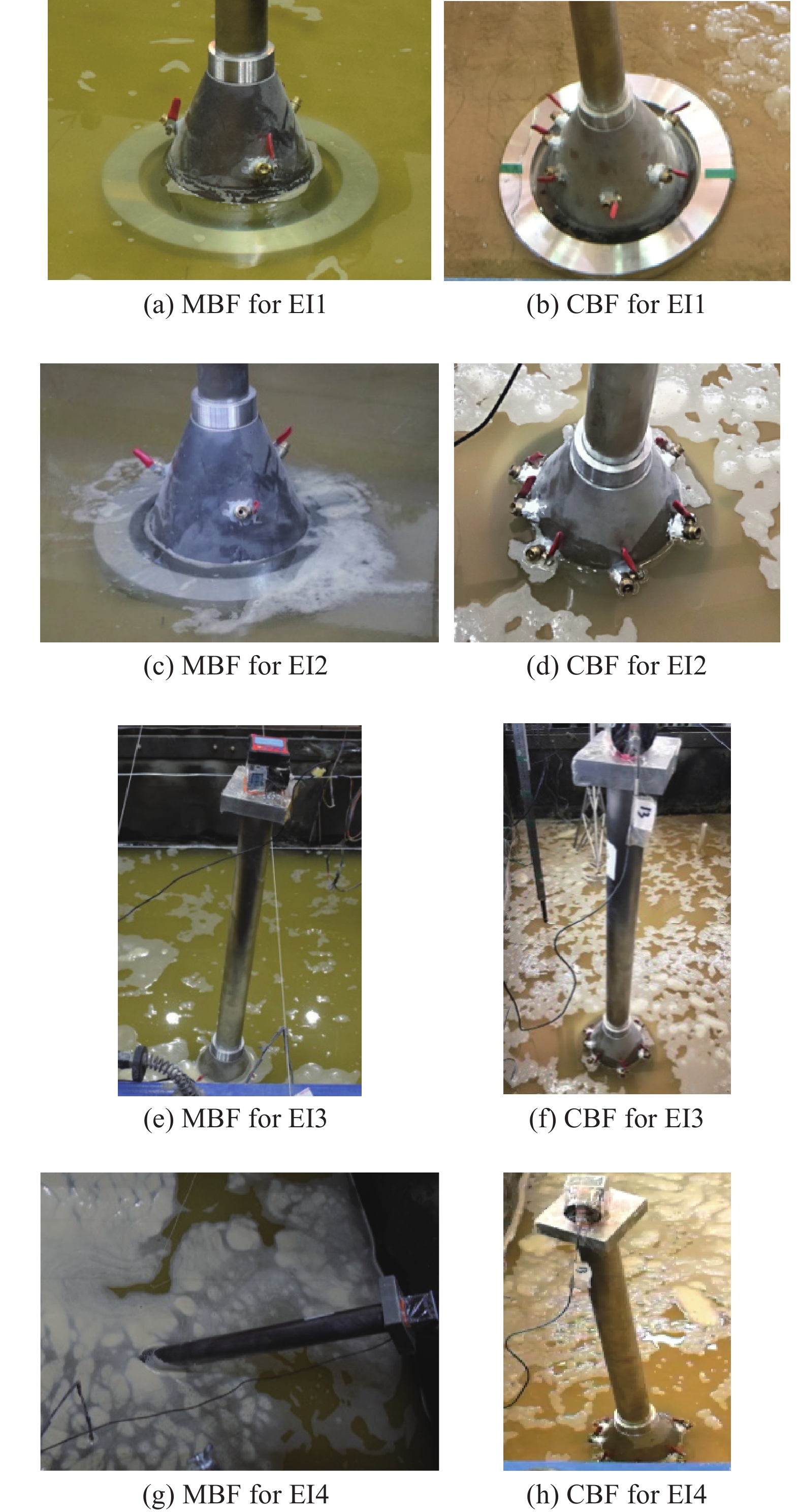
The test phenomena of MBF and CBF are shown in Fig. 8.
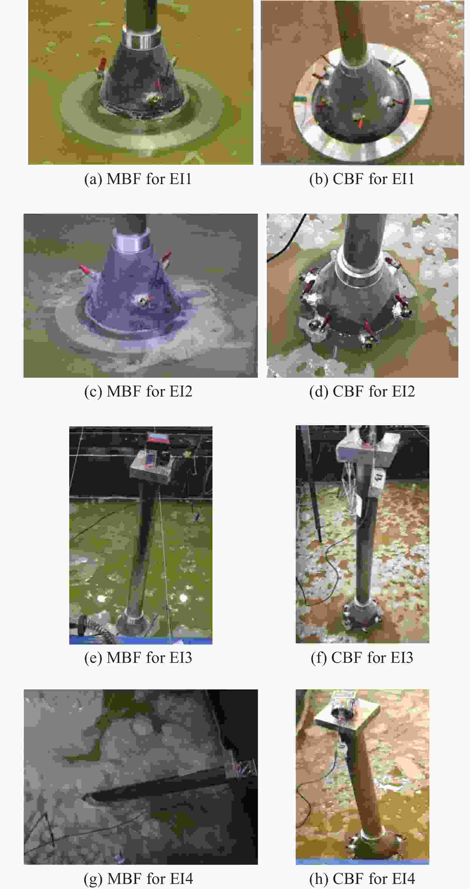
Figure 8. Test phenomena of MBF and CBF
Under seismic wave with the peak acceleration of 0.1 g, the structure and soil of MBF and CBF had little change. When the peak acceleration reached 0.175 g, it was found that there was obvious bubbling outside the bucket of MBF and CBF, and some foam gathered on the soil surface near the bucket. During the vibration process, the tower tube on the upper part of the bucket foundation swayed slightly with the vibration of the model box. After the test, it basically recovered to the vertical state without obvious inclination, indicating that the soil near the outer wall of the bucket still maintained its bearing capacity. With the peak of input acceleration reaching 0.22 g, the saturated soil near the bucket began bubbling, and a large amount of foam gathered on the surface of the soil outside the bucket, which indicates that the free field around and far away from the bucket foundation had been liquefied under the earthquake. The bucket foundation and its upper tower tube also swung violently along the vibration direction with the shaking of the soil box. It can be observed that the MBF did not return to the initial state after earthquake, but produced a large tilt. It can be considered that the bucket foundation at this time no longer meets the bearing requirements. CBF produced a small amount of inclination, but the inclination was obviously smaller than that of MBF. When the acceleration increased to 0.4 g, the foundation soil of the two kinds of bucket foundations produced much more bubbles, and the surface of the site was completely covered by foam. MBF and its upper tower tube vibrated violently with the shaking table, and finally the structure collapsed, completely losing its bearing capacity. Since the bucket foundation itself has not suffered any structural damage, it can be inferred that the failure of the bearing capacity of the structure is completely caused by the liquefaction of the foundation soil. CBF and superstructure also maintained a certain inclination after the earthquake, but did not collapse.
2) Phenomena of TBJF and FBJF
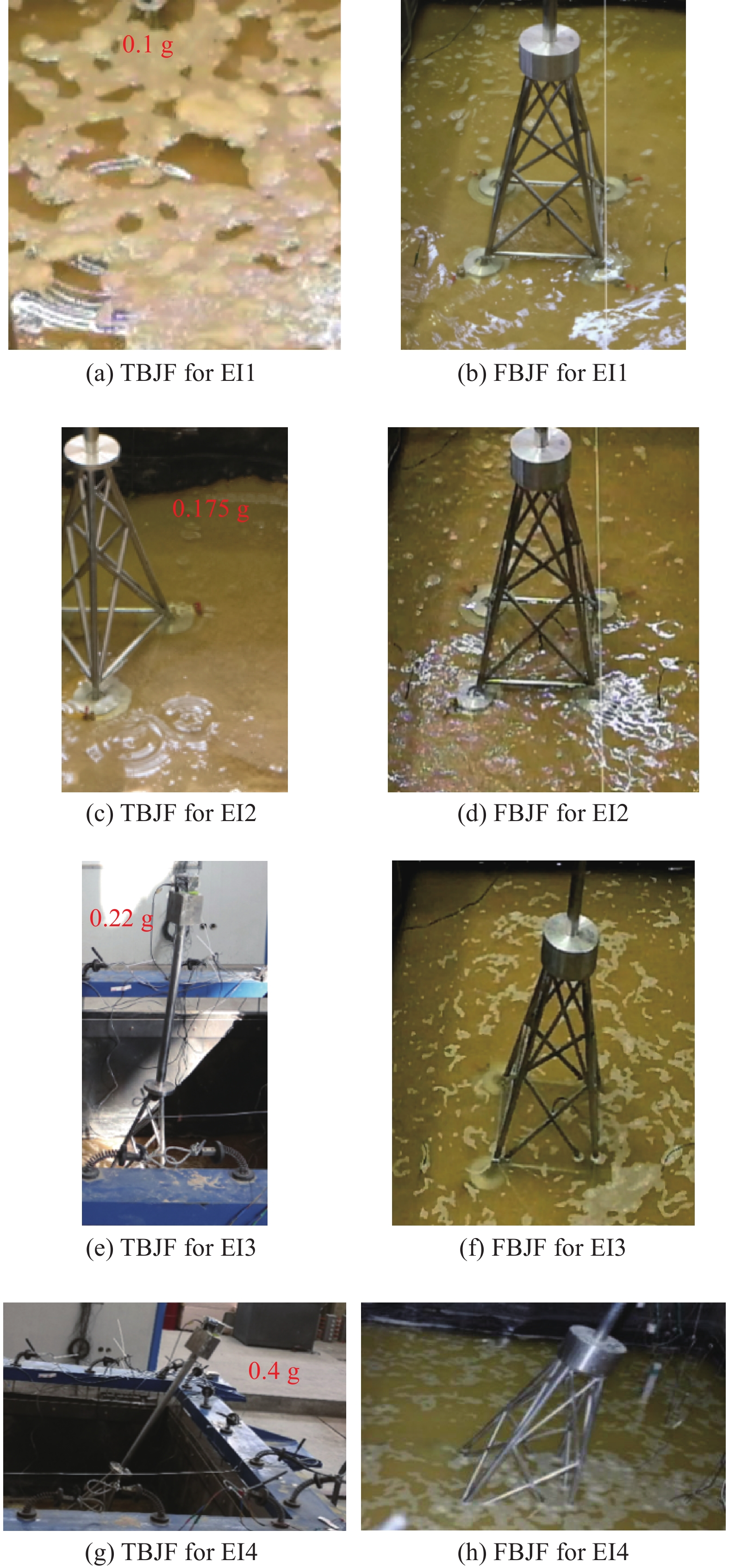
The phenomena of TBJF and FBJF during the test process are shown in Fig. 9.
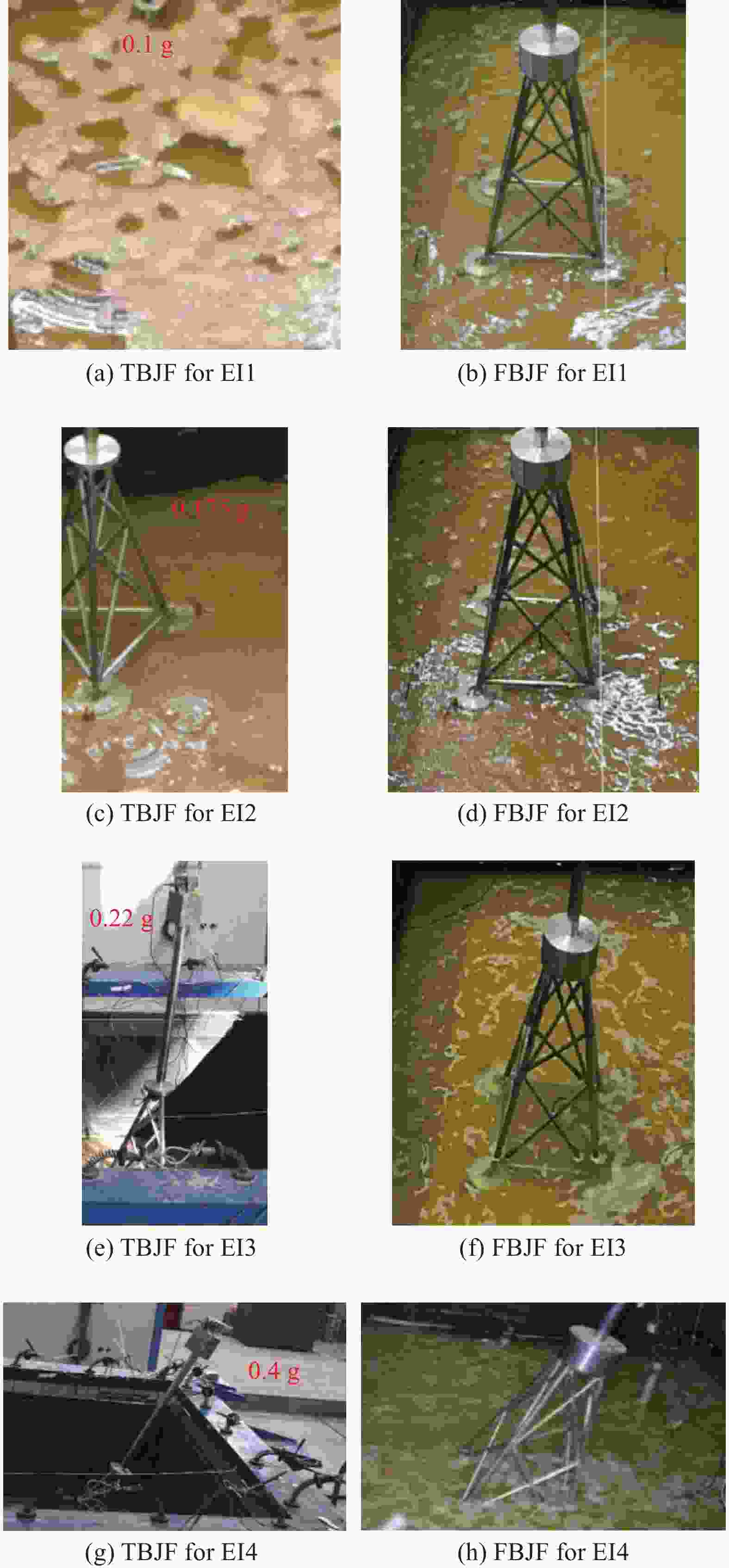
Figure 9. Test phenomena of TBJF and FBJF
As the peak acceleration was 0.1 g, there were bubbles on the surface of the soil outside the bucket during the vibration process, there was no obvious change in the TBJF, and there was a certain fluctuation in the water surface of the soil outside the FBJF, but no obvious bubbling phenomenon occurred. When the peak value of acceleration reached 0.175 g, a large number of bubbles appeared on the surface of the soil outside the TBJF, and there were small bubbles around the bucket; A small amount of bubbles appeared on the soil surface around the FBJF, especially in the quadrilateral formed by FBJF, which resulted in sand blasting and water gushing. At the same time, it was obvious that the foundation model had a certain degree of subsidence. When the peak acceleration reaching 0.22 g, the sand blasting and water gushing phenomenon occurred on the soil surface of the TBJF. At the same time, it was observed that the model box vibrated violently, the maximum horizontal displacement reaches 10 cm, and the test model had a large inclination. The bucket at the front side tilted upwards, and part of the soil surface was pulled out. At this time, the stability of the foundation had been greatly reduced, and uneven settlement had occurred. After the vibration, the inclination of the foundation model still increased gradually. At this time, FBJF also had a certain degree of inclination, but the inclination was obviously smaller than TBJF. When the peak acceleration of the input seismic wave reached 0.4 g, the surface of the foundation soil of the TBJF had a relatively severe phenomenon of sand blasting and water gushing, the inclination of the foundation model further increased, the model collapsed, and the bearing capacity of soil foundation was totally lost. Meanwhile, the soil surface of FBJF had obvious sand blasting and water gushing phenomenon, and the one-side bucket tilted upwards, with a large angle inclination. However, it was still not completely collapsed, and the foundation soil still had certain bearing capacity.
-
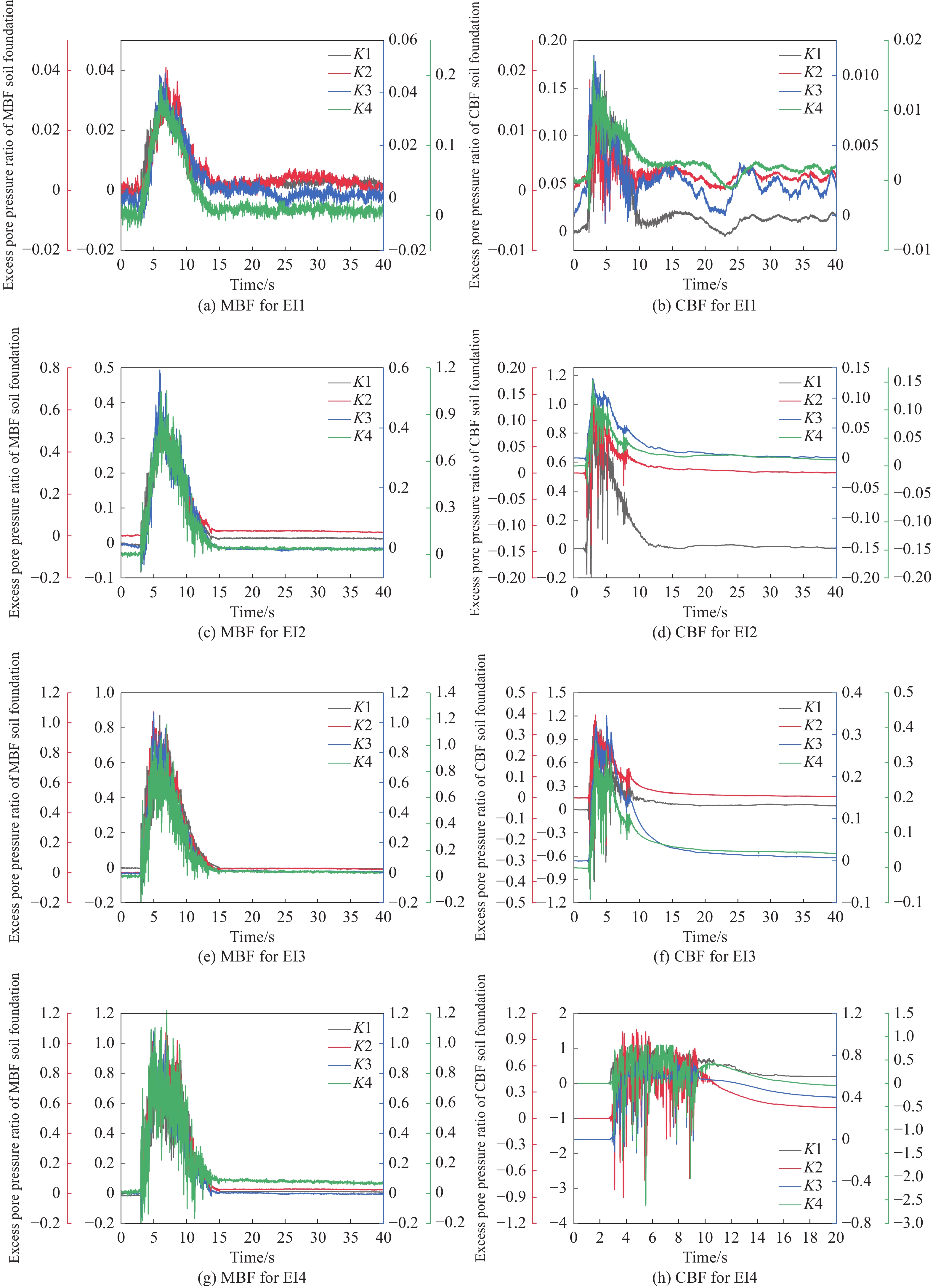
In order to better analyze the process and distribution of foundation liquefaction, the effective stress principle is used to determine whether the soil liquefaction occurs according to the excess pore pressure ratio, thus the excess pore water pressure is converted into the excess pore pressure ratio R, as shown in Fig. 10. The excess pore pressure ratio
$R = \dfrac{{{\rm{excess}}\;{\rm{pore}}\;{\rm{water}}\;{\rm{pressure}}\;{\rm{of}}\;{\rm{soil}}}}{{{\rm{initial}}\;{\rm{effective}}\;{\rm{stress}}\;{\rm{of}}\;{\rm{soil}}}}$ . When ratio R reaches 1.0, it means that the upper load of the soil has been fully borne by pore water and the soil has liquefied.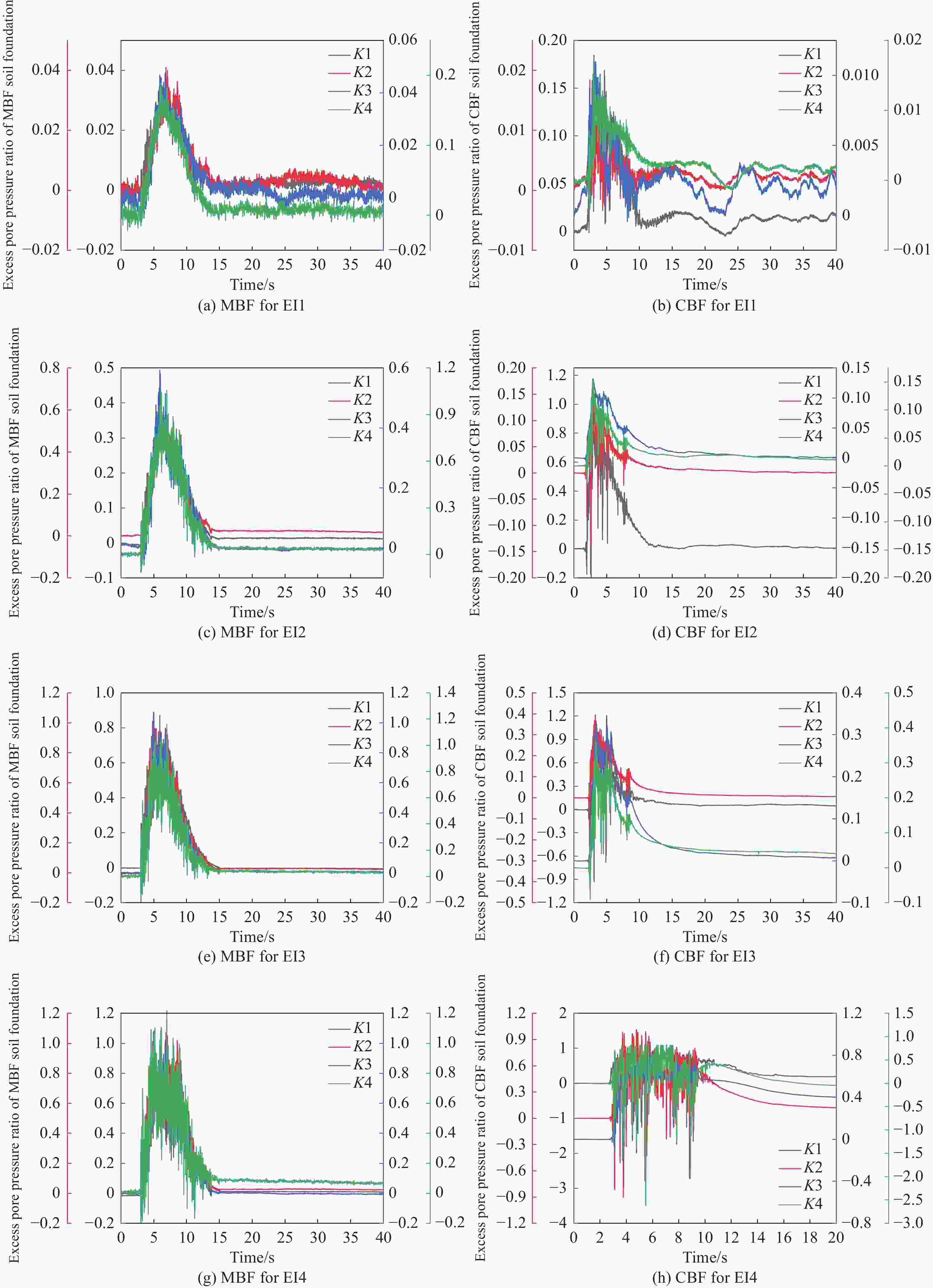
Figure 10. The ratio R of MBF and CBF
1) Excess pore pressure ratio R of MBF and CBF
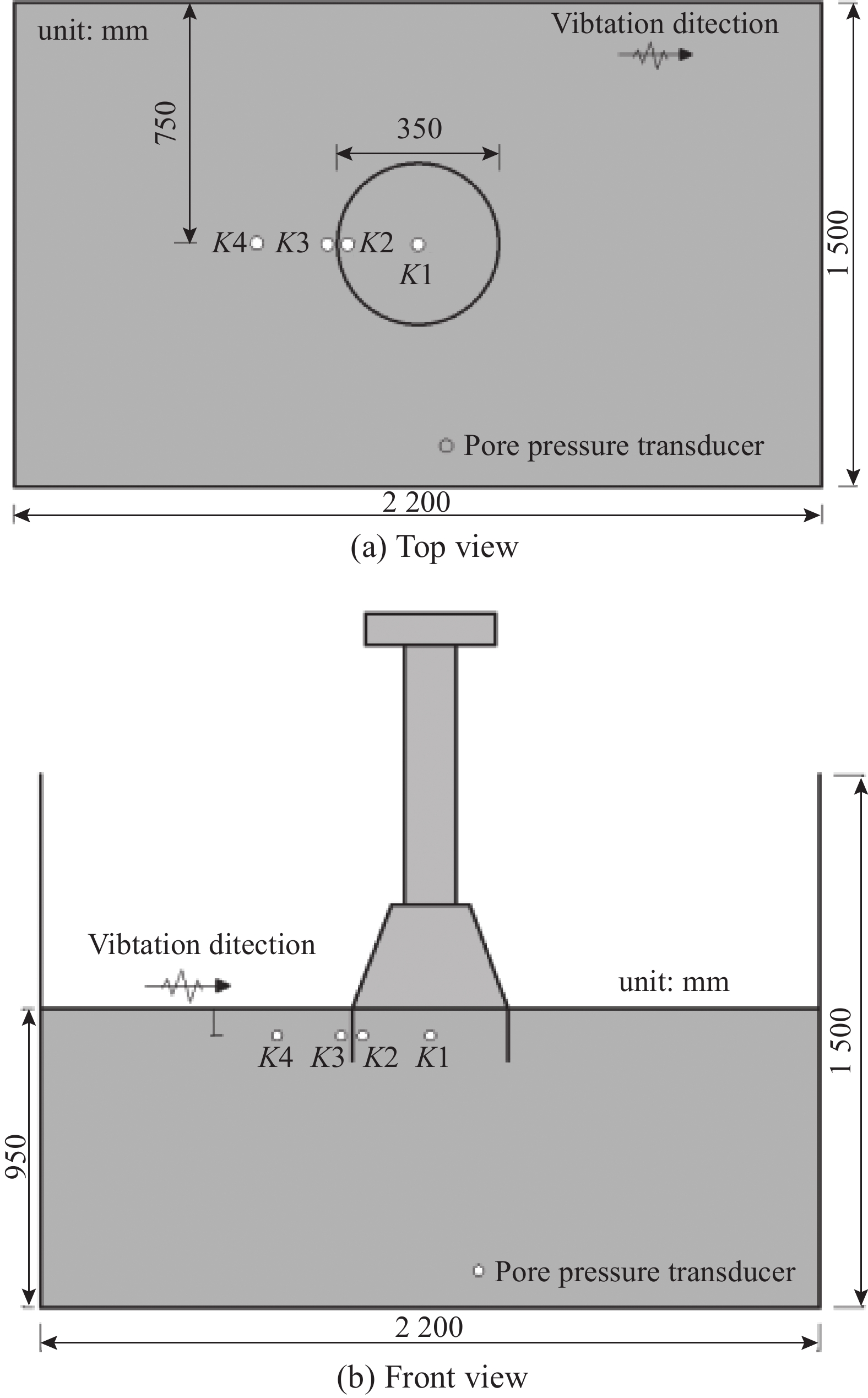
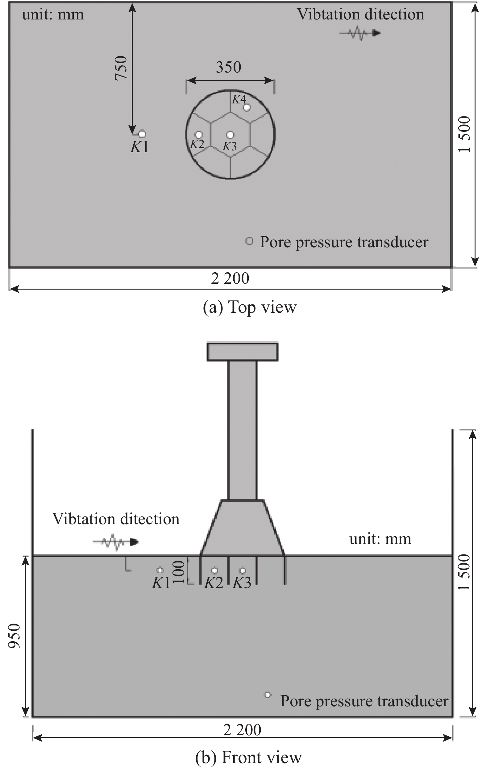
The pore water pressure measure points of MBF and CBF in the test are shown in Fig. 11 and Fig. 12.
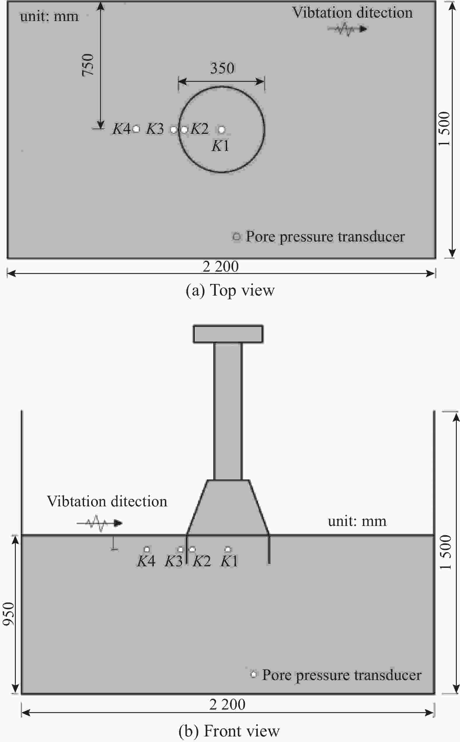
Figure 11. Arrangement of sensors for MBF
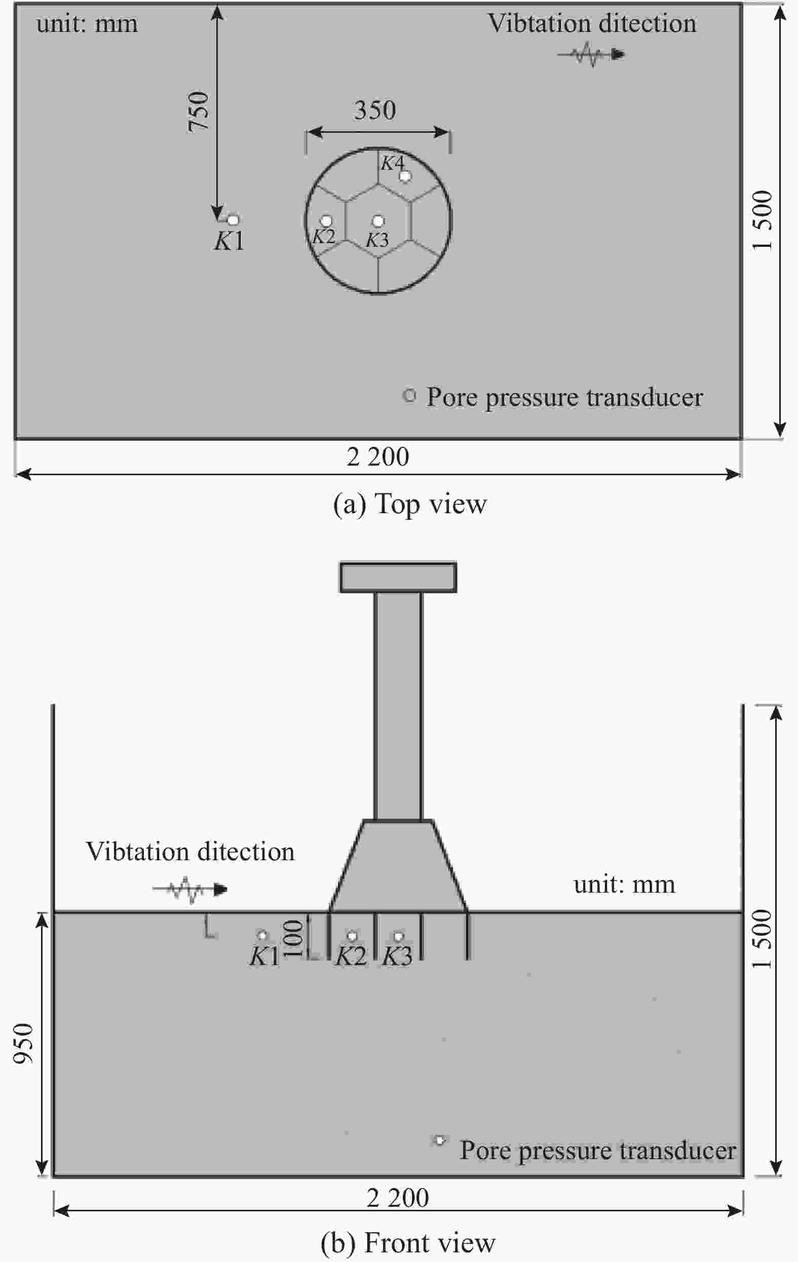
Figure 12. Arrangement of sensors for CBF
The excess pore pressure of MBF and CBF at different measure points are shown in Fig. 10, and the measure points K1, K2, K3 and K4 are shown in Fig. 12. The ratio R at the center of the bucket is the lowest, and the peak value under EI1 condition is 0.036; The ratio R of soil at 0.5D (D is the diameter of bucket) outside the bucket is the largest, and the peak value under EI1 condition is less than 1.0, without liquefaction. The ratio R of the soil inside the bucket is significantly lower than that of the soil outside the bucket, which indicates that the anti-liquefaction ability of the soil inside the bucket is improved with restraint of the bucket. The largest ratio R of CBF also appeared outside the bucket, and the difference of the ratio R at each position inside the bucket is small, among which the ratio R of K3 is the lowest, which is at the center of the bucket. And the ratio R at the center of CBF is significantly smaller than that of MBF.
Under EI2 test condition, for the soil of MBF, the ratio R at 0.5D outside the bucket has reached 1.0, indicating that the soil at this location has been liquefied. The peak value of the ratio R at the center of the bucket is only 36% of that at 0.5D outside the bucket. For CBF, the ratio R at K1 has reached 1.0, indicating that the soil at this location has undergone liquefaction. The maximum ratio R in the bucket appears at K2, with a peak value of 0.16; The ratio R at the center of the bucket is the lowest, with a peak value of 0.13. The liquefaction risk is small, indicating that the liquefaction resistance of the soil inside the bucket is significantly greater than that of the soil outside the bucket.
Under test condition of EI3, the ratio R at the inner wall, outer wall and 0.5D of CBF has reached 1.0, and liquefaction has occurred. However, the ratio R at the center of the bucket at the same height is 0.87, with a high risk of liquefaction. At this time, except the ratio R at K1 outside the bucket exceeding 1.0, the maximum ratio R appears at K2, with a peak value of 0.4, without liquefaction.
Under EI4, liquefaction has occurred at all the monitoring positions inside and outside MBF, which is also consistent with the test phenomenon of model collapse. At this time, the ratio R of CBF at K2 reaches 1.0, indicating that the soil at this location is liquefied. The ratio R at K4 is the lowest, with a peak value of 0.5; The peak value of ratio R at the center of the bucket reached 0.8, and no liquefaction occurred.
To sum up, both MBF and CBF show the same law, that is, the ratio R of the soil inside the bucket is smaller than the soil outside the bucket, and the liquefaction resistance is better. The analysis of its mechanism shows that the additional load of the superstructure of the bucket foundation and the hoop effect of the bucket wall significantly improve the initial effective stress of the soil. According to the definition of the ratio R, the greater the initial effective stress, the smaller the ratio R is, and the soil will be less prone to liquefaction; At the same time, the bucket foundation has a compaction effect on the soil particles, and the shear shrinkage of the sand becomes weaker, while the shear shrinkage of the sandy soil under the reciprocating shear stress is an important reason for the rise of pore pressure, thus the increase of the pore pressure is suppressed after compaction, and the liquefaction resistance is improved. The ratio R of the soil in the middle compartment of CBF is the smallest, which is caused by the strongest constraint effect of the bucket at this position. In addition, K4 is located adjacent to K2, but its ratio R is smaller than K2 under EI4, indicating that the response of soil in different compartments is not the same. This may be due to the larger movement of the bucket along the vibration direction during earthquakes, while the compartment where K4 is located has a certain angle with the vibration direction, and the relative motion between the inside soil and the bucket is also relatively weak.
Fig. 13 shows the peak value of ratio R at the center of the bucket and 0.5D outside the bucket for CBF and MBF respectively. It can be found that when the same acceleration peak value is input, the ratio R at the center of the CBF is significantly smaller than that of the MBF. Under the EI3 condition, the difference between the ratio R at the center of MBF and CBF is the largest, indicating that CBF has a greater role in improving the liquefaction resistance of the soil in the bucket than MBF. This is due to the existence of the compartment plate, which divides CBF into several smaller compartments. The hoop effect of the compartment plate and the bucket wall on the inside soil is stronger. The bucket soil is more inclined to become a whole and is not easy to produce relative displacement. The soil inside the bucket is subject to greater restraint, and the effective stress is increased. At the same time, the soil particles are squeezed and the shear shrinkage is weakened, thus the soil is less prone to liquefaction. Therefore, under the action of earthquake, the increase of pore pressure and the ratio R is smaller, as the result of which, the liquefaction resistance is improved. However, the difference of the ratio R between CBF and MBF at 0.5D outside the bucket is small, indicating that the ratio R at this location is less influenced by the structure.
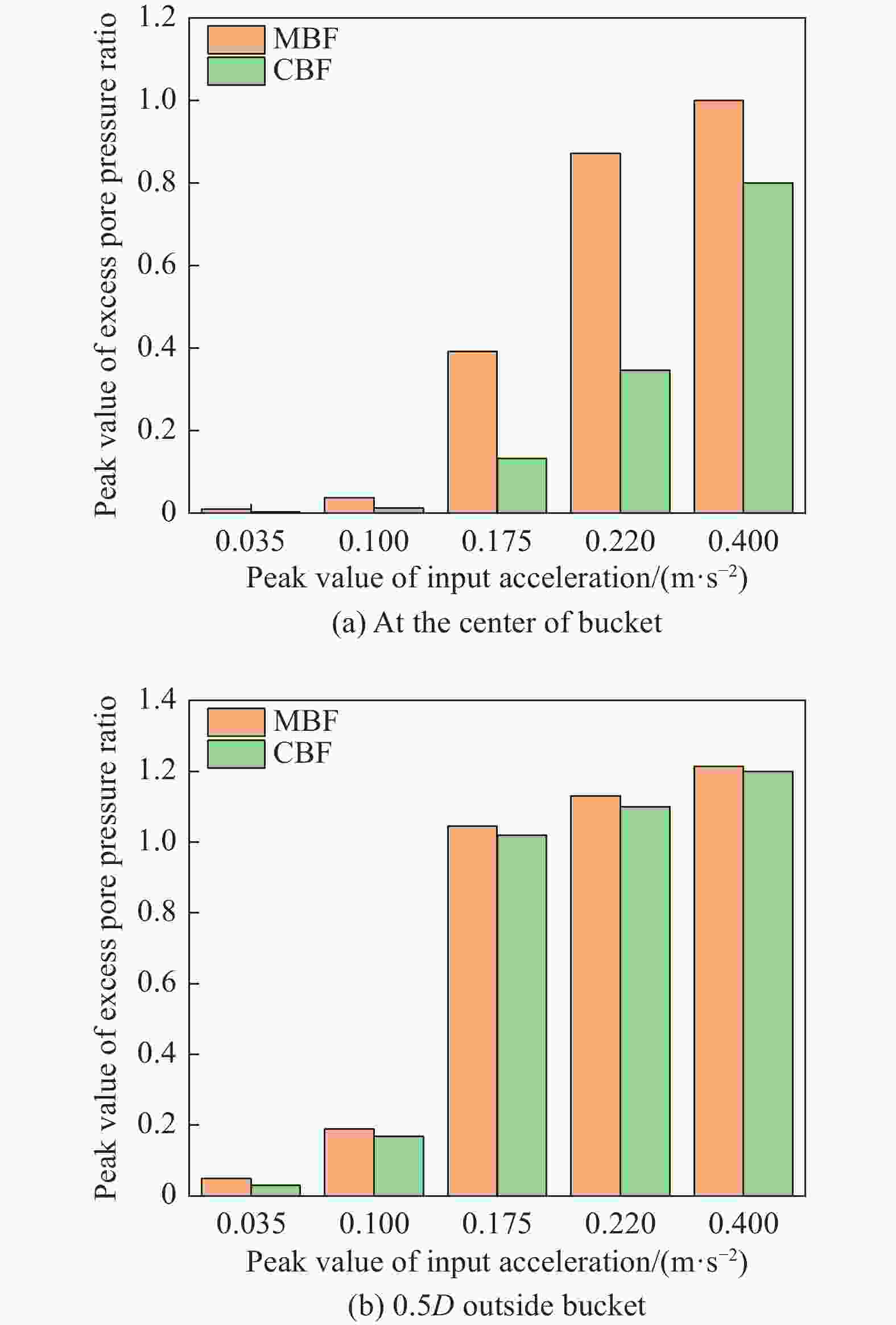
Figure 13. Comparison of ratio R of MBF and CBF
2) Excess pore pressure ratio R of TBJF and FBJF
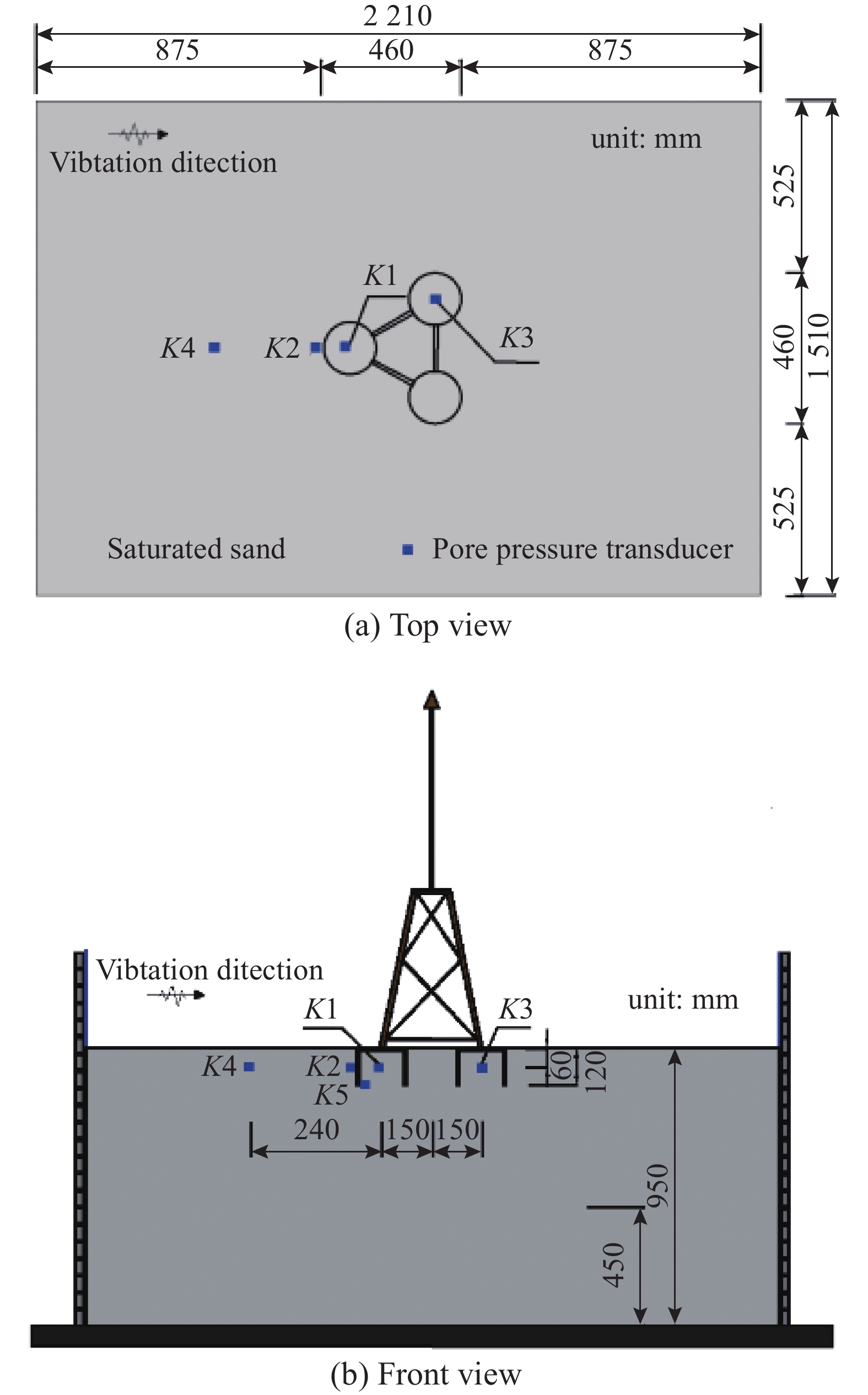
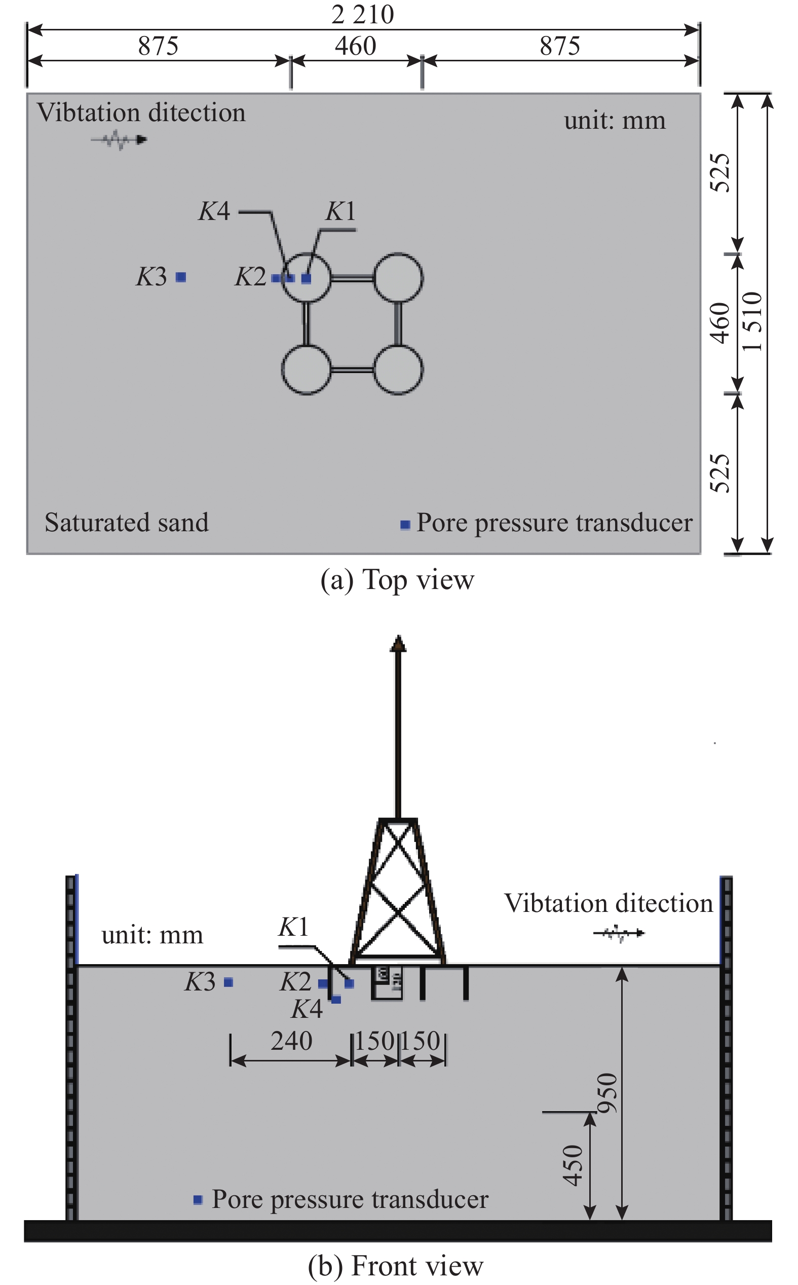
The pore pressure monitoring points of TBJF and FBJF are shown in Fig. 14 and Fig. 15.
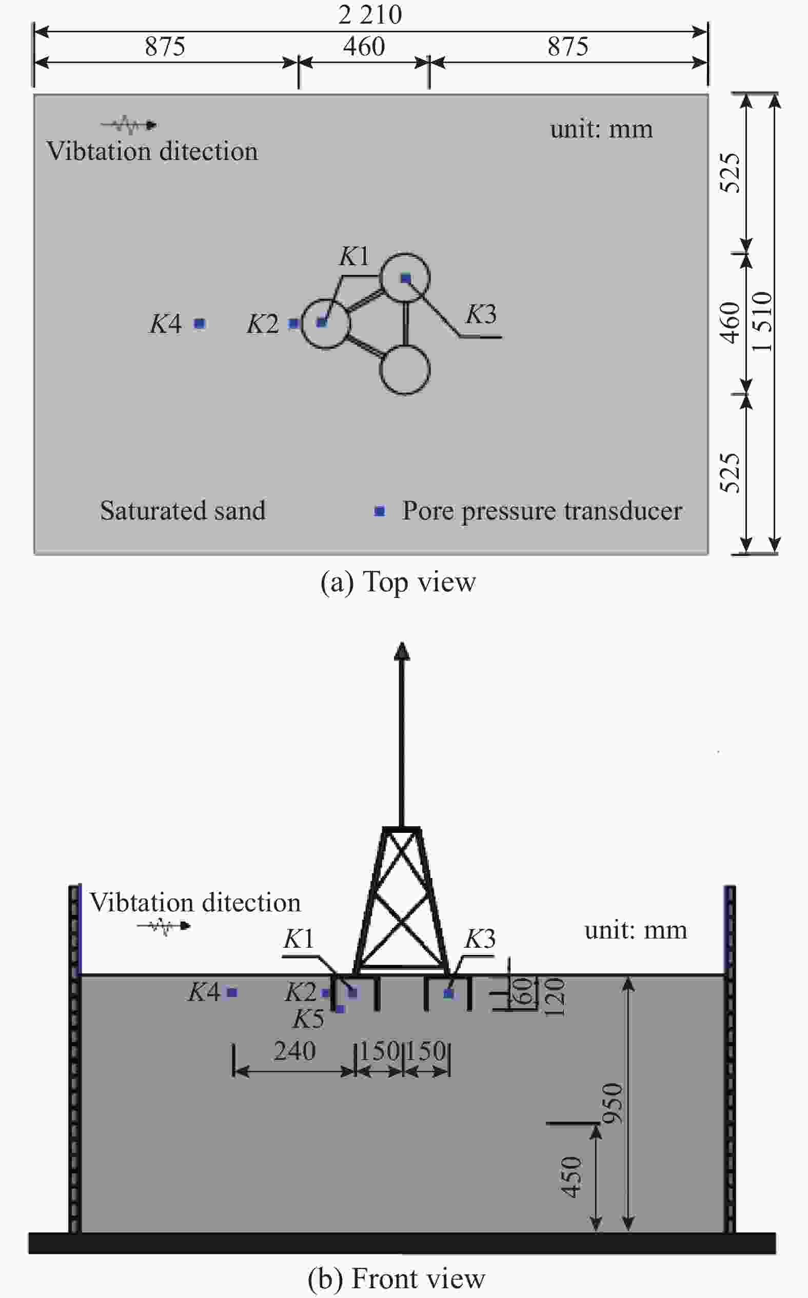
Figure 14. Arrangement of sensors for TBJF
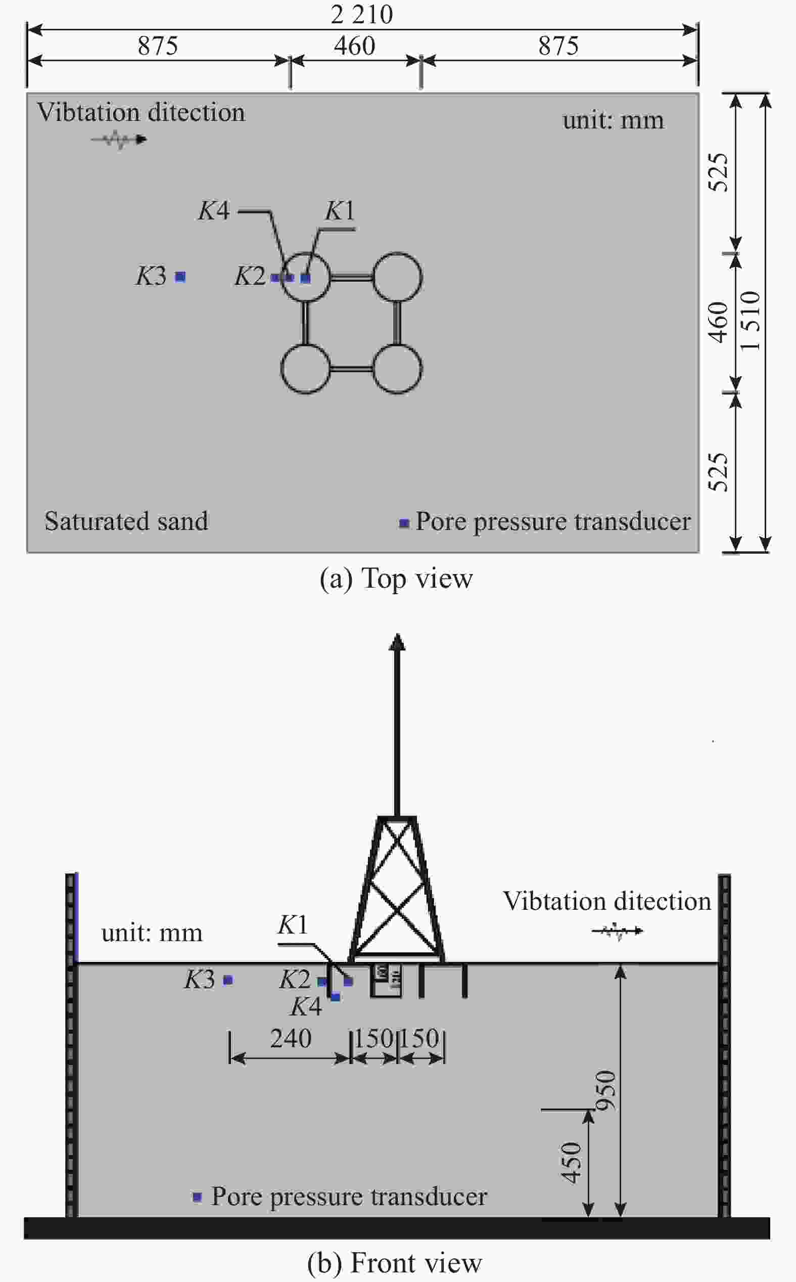
Figure 15. Arrangement of sensors for FBJF
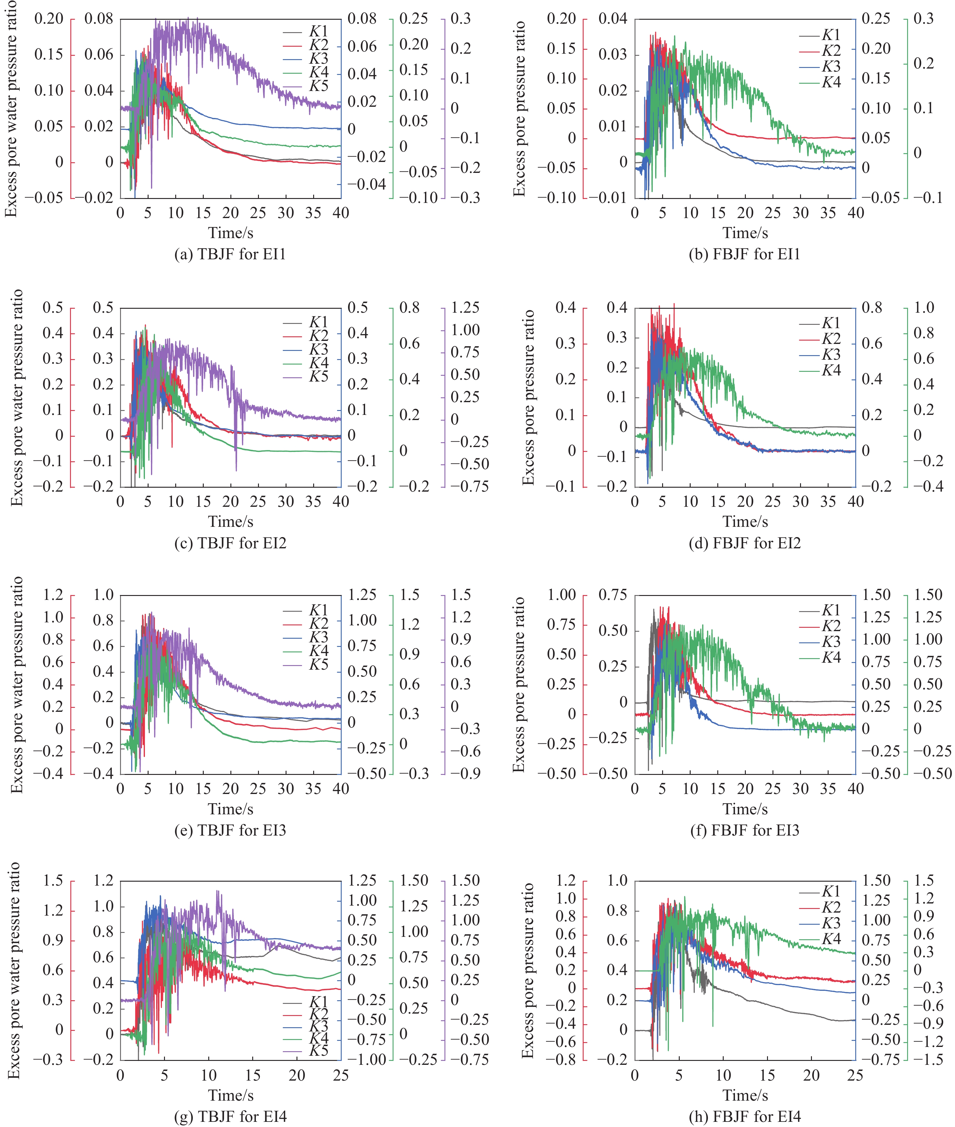
The excess pore pressure of TBJF and FBJF at different measure points are shown in Fig. 16, and the measure points K1, K2, K3, K4 and K5 are shown in Fig. 15. Under condition EI1, TBJF and FBJF are not liquefied; However, when the acceleration reaches 0.175 g, the excess pore pressure at each position of TBJF and FBJF increases significantly, and the ratio R of soil at the bottom of bucket reaches 1.0, resulting in liquefaction, but the ratio R inside FBJF is lower than that of TBJF. For TBJF, when the peak acceleration is 0.22 g, the ratio R of the soil outside the bucket and near the bucket also reaches 1.0. When the peak acceleration reaches 0.4 g, the ratio R of the soil inside the bucket reaches 1.0, at this time, the sand at each measuring point is liquefied, and the bearing capacity is lost. The sequence of sand at each measuring point reaching liquefaction state is: the bottom of bucket>outside the bucket>near the bucket foundation>inside the bucket. Besides, the ratio R of K1 is larger than K3 under EI4 condition, indicating that the response of soil in different bucket for TBJF is not the same. This may be caused by structural asymmetry, for there is only one bucket subjected to seismic load where K1 is located, while two buckets could disperse seismic loads for K3.
Figure 16. The ratio R of TBJF and FBJF
For FBJF, when the peak acceleration is 0.22 g, the ratio R at the bottom of the bucket and outside the bucket reaches 1.0, which corresponds to the phenomenon of a large number of bubbles near the bucket foundation on the macro level. The peak value of ratio R near the bucket wall is about 0.8, and the value in the bucket is less than 0.7. It can be concluded that the bucket foundation can improve the liquefaction resistance of sand under earthquake. When the input seismic wave acceleration is 0.4 g, the soil near the bucket wall also reaches the liquefaction state, and the soil inside the bucket still maintains a certain bearing capacity. Although the bucket foundation has a large angle of inclination, it does not topple down. It can be seen that FBJF has the better anti-liquefaction ability than TBJF.
Comparing the test results of TBJF and FBJF, it is found that both the three-bucket and four-bucket foundations show that the ratio R of the soil inside the bucket is lower than the soil outside the bucket. In addition, the soil near the bottom of bucket is greatly disturbed by the bucket wall, and the stress concentration tends to occur. During the vibration process, the soil particles are more prone to dislocation, as the result of which, the sandy soil at this location reaches the liquefaction state earlier.
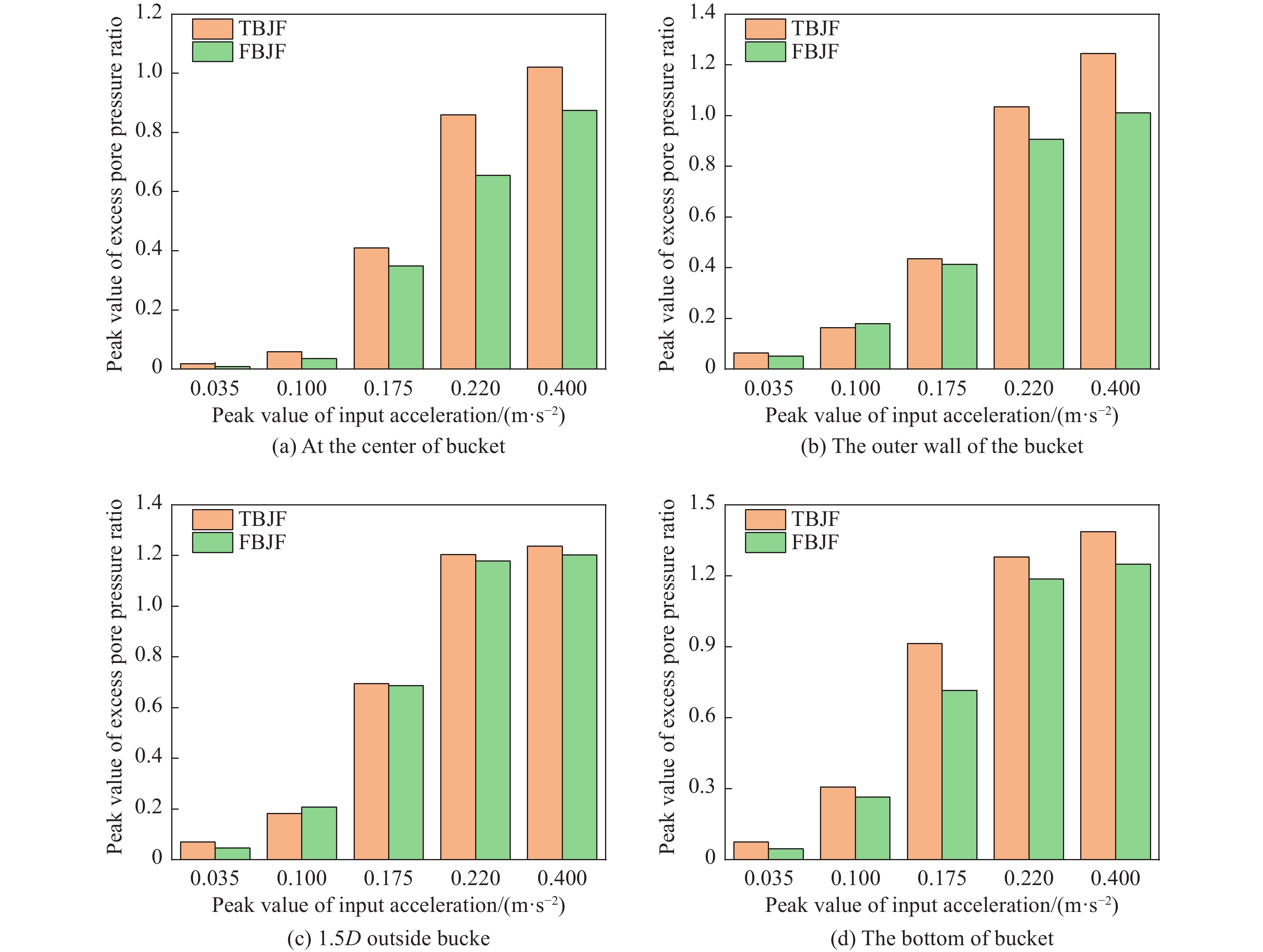
The peak values of ratio R for TBJF and FBJF under the same seismic wave are compared. Select the measuring points at the center of the bucket, near the outer wall of the bucket, 1.5D (D is the bucket diameter) outside the bucket and the bottom of the bucket wall for comparison, as shown in Fig. 17.
Figure 17. Comparison of the ratio R of TBJF and FBJF
It can be seen from Fig. 17 that under the same seismic wave, the ratio R at each measuring point of FBJF is generally lower than that of TBJF. At the same time, the ratio R at the measuring point rises with the increase of the peak acceleration of the seismic wave, and the gap between the two foundations also increases. This shows that FBJF has a more significant effect on the liquefaction resistance of sandy soil foundation than TBJF, and this effect will increase with the intensity of seismic. This is because FBJF has a larger self-weight, which makes the soil inside and around the bucket foundation bear the stronger compaction, and the shear shrinkage is weaker, thus its liquefaction resistance improved; In addition, compared with TBJF, FBJF has the advantages of symmetry, and the larger contact area with the soil, and the more stable structure. When subjected to earthquake, it is not easy to topple down in a single direction. When the large earthquake occurs, TBJF is prone to tilt in a single direction, the soil is disturbed and the excess pore pressure rises sharply, and the ratio R also increases. Therefore, when the input acceleration increases, the gap between the peak values of the R ratio for two bucket foundations increases.
-
The conclusions obtained from shaking table test are as follows.
1) The four types of bucket foundations all show a common law, that is, the ratio R of the soil inside bucket is significantly inhibited, which is because the additional load on the upper part of the bucket foundation changes the initial stress field of the soil. The initial stress of the soil increases, thus the shear shrinkage becomes weak, and the liquefaction risk decreases. At the same time, the restriction effect of bucket wall also improves the anti-liquefaction ability of soil.
2) Through the comparison of MBF and CBF, it is found that the compartment plate strengthens the hoop effect of the bucket on the soil, thus the ratio R of soil for CBF is lower than MBF, and the liquefaction risk is lower.
3) By the comparison of TBJF and FBJF, it is found that the anti-liquefaction capacity of FBJF is significantly higher than that of TBJF. This is because FBJF has the advantages of large self-weight and symmetrical structure, and the compaction effect on the foundation soil is more obvious, giving rise to the better anti-liquefaction capacity. At the same time, it is found that the liquefaction risk at the bottom of the bucket is high, which is caused by the extrusion and collision between the soil under the bucket foundation and the bottom of bucket wall.
Research on Liquefaction Resistance of Bucket Foundation for Offshore Wind Turbines
doi: 10.16516/j.gedi.issn2095-8676.2023.04.003
- Received Date: 2023-05-21
- Rev Recd Date: 2023-06-13
- Available Online: 2023-07-25
- Publish Date: 2023-07-10
-
Key words:
- bucket foundation /
- liquefaction /
- shaking table test /
- pore pressure /
- seismic response
Abstract:
| Citation: | LI Jingyi, ZHANG Puyang, LE Conghuan, DING Hongyan, QI Xiaoliang. Research on Liquefaction Resistance of Bucket Foundation for Offshore Wind Turbines[J]. SOUTHERN ENERGY CONSTRUCTION, 2023, 10(4): 18-31. doi: 10.16516/j.gedi.issn2095-8676.2023.04.003

|


 DownLoad: