• Peer Review
  • Non-profit
  • Global Open Access
  • Green Channel for Rising Stars
Volume 10 Issue 5
Sep.  2023
Turn off MathJax
Article Contents

LIN Cong, LI Xiangfeng, GUO Fang. Research on Fault Current Controller of DC Microgrid[J]. SOUTHERN ENERGY CONSTRUCTION, 2023, 10(5): 50-56. doi: 10.16516/j.gedi.issn2095-8676.2023.05.007
Citation: LIN Cong, LI Xiangfeng, GUO Fang. Research on Fault Current Controller of DC Microgrid[J]. SOUTHERN ENERGY CONSTRUCTION, 2023, 10(5): 50-56. doi: 10.16516/j.gedi.issn2095-8676.2023.05.007

Research on Fault Current Controller of DC Microgrid

doi: 10.16516/j.gedi.issn2095-8676.2023.05.007
  • Received Date: 2022-08-24
  • Rev Recd Date: 2022-11-19
  • Available Online: 2023-09-06
  • Publish Date: 2023-09-10
  •   Introduction  With the rapid development of AC/DC distribution networks and distributed generation technology, the role of DC microgrids in distribution networks is becoming increasingly important and will become an important component of future distribution networks. Due to the small coverage area and low line impedance of the DC microgrid, when an inter pole short circuit fault occurs, the fault current increases rapidly and has a large amplitude, which can reach more than 10 times the rated working current. This makes it difficult to set the protection of DC microgrids and requires high equipment selection, which restricts the rapid development of DC microgrids.   Method  In response to the above issues, taking the DC microgrid as the research object, starting from the working principle of inter pole faults in the DC microgrid, the fault characteristics on the DC side of the DC microgrid were analyzed. In response to the shortcomings of existing main current limiting methods, a voltage controllable fault current controller was proposed to achieve precise control of fault current. The simulation model of DC microgrid and fault current controller was built for simulation verification.   Result  The simulation results show that the fault current controller can significantly reduce the fault current and achieve precise control of the fault current, making the system controllable before and after the fault without locking the protection. During steady-state operation, the fault current controller can also assist the VSC (Voltage Source Converter) in further stabilizing the DC bus voltage.   Conclusion  To cooperate with the normal operation of the relay protection device and avoid VSC triggering overcurrent protection blocking, it is recommended to set the fault current control range between 1~2 pu.
  • [1] 薛士敏, 齐金龙, 刘冲. 直流微网保护综述 [J]. 中国电机工程学报, 2016, 36(13): 3404-3412. DOI:  10.13334/j.0258-8013.pcsee.160148.

    XUE S M, QI J L, LIU C. A research review of protection for DC microgrid [J]. Proceedings of the CSEE, 2016, 36(13): 3404-3412. DOI:  10.13334/j.0258-8013.pcsee.160148.
    [2] 薛士敏, 齐金龙, 刘冲, 等. 直流微网接地方式及新型保护原理 [J]. 电网技术, 2018, 42(1): 48-55. DOI:  10.13335/j.1000-3673.pst.2017.1409.

    XUE S M, QI J L, LIU C, et al. A research of grounding mode and new protection principle for DC microgrids [J]. Power system technology, 2018, 42(1): 48-55. DOI:  10.13335/j.1000-3673.pst.2017.1409.
    [3] 张宇涵, 杜贵平, 雷雁雄, 等. 直流微网混合储能系统控制策略现状及展望 [J]. 电力系统保护与控制, 2021, 49(3): 177-187. DOI:  10.19783/j.cnki.pspc.200461.

    ZHANG Y H, DU G P, LEI Y X, et al. Current status and prospects of control strategy for a DC micro grid hybrid energy storage system [J]. Power system protection and control, 2021, 49(3): 177-187. DOI:  10.19783/j.cnki.pspc.200461.
    [4] DRAGIČEVIĆ T, LU X N, VASQUEZ J C, et al. DC microgrids-part Ⅱ: a review of power architectures, applications, and standardization issues [J]. IEEE transactions on power electronics, 2016, 31(5): 3528-3549. DOI:  10.1109/TPEL.2015.2464277.
    [5] MONADI M, ZAMANI M A, IGNACIO CANDELA J, et al. Protection of AC and DC distribution systems embedding distributed energy resources: a comparative review and analysis [J]. Renewable and sustainable energy reviews, 2015, 51: 1578-1593. DOI:  10.1016/j.rser.2015.07.013.
    [6] 于涛. 基于分布式电源的微电网控制策略研究 [D]. 哈尔滨: 哈尔滨工程大学, 2020. DOI: 10.27060/d.cnki.ghbcu.2020.001247.

    YU T. Research on microgrid control strategy based on distributed power supply [D]. Harbin: Harbin Engineering University, 2020. DOI: 10.27060/d.cnki.ghbcu.2020.001247.
    [7] LIANG B M, KANG L, ZHANG Z Y, et al. Simulation analysis of grid-connected AC/DC hybrid microgrid [C]//2018 13th IEEE Conference on Industrial Electronics and Applications (ICIEA), Wuhan, China, May 31-June 2, 2018. New York, USA: IEEE, 2018: 969-974. DOI: 10.1109/ICIEA.2018.8397852.
    [8] 薛士敏, 黄仁乐, 高峰, 等. 基于暂态电流突变量的直流配电系统快速纵联保护新原理 [J]. 供用电, 2016, 33(8): 37-44. DOI:  10.19421/j.cnki.1006-6357.2016.08.007.

    XUE S M, HUANG R L, GAO F, et al. High-speed pilot protection principle for DC distribution system based on the difference of transient currents [J]. Distribution & utilization, 2016, 33(8): 37-44. DOI:  10.19421/j.cnki.1006-6357.2016.08.007.
    [9] 焦皎, 孟润泉, 任春光, 等. 交直流微电网AC/DC双向功率变换器控制策略 [J]. 电力系统保护与控制, 2020, 48(16): 84-92. DOI:  10.19783/j.cnki.pspc.191124.

    JIAO J, MENG R Q, REN C G, et al. Bidirectional AC/DC interlinking converter control strategy for an AC/DC microgrid [J]. Power system protection and control, 2020, 48(16): 84-92. DOI:  10.19783/j.cnki.pspc.191124.
    [10] 周钰, 张浩, 陈锐, 等. 直流微电网控制保护策略研究 [J]. 南方能源建设, 2020, 7(4): 61-66. DOI:  10.16516/j.gedi.issn2095-8676.2020.04.009.

    ZHOU Y, ZHANG H, CHEN R, et al. Research on strategy of DC micro-grid control and protection [J]. Southern energy construction, 2020, 7(4): 61-66. DOI:  10.16516/j.gedi.issn2095-8676.2020.04.009.
    [11] 王灿, 杜船, 徐杰雄. 中高压直流断路器拓扑综述 [J]. 电力系统自动化, 2020, 44(9): 187-199. DOI:  10.7500/AEPS20191021006.

    WANG C, DU C, XU J X. Review of topologies for medium-and high-voltage DC circuit breaker [J]. Automation of electric power systems, 2020, 44(9): 187-199. DOI:  10.7500/AEPS20191021006.
    [12] FRANCK C M. HVDC circuit breakers: a review identifying future research needs [J]. IEEE transactions on power delivery, 2011, 26(2): 998-1007. DOI:  10.1109/TPWRD.2010.2095889.
    [13] 杨勇, 王文杰, 刘亚萍, 等. 基于大规模风、光并网外送需求的高压直流混合式直流断路器研究 [J]. 可再生能源, 2021, 39(2): 237-244. DOI:  10.3969/j.issn.1671-5292.2021.02.015.

    YANG Y, WANG W J, LIU Y P, et al. Hybrid HVDC breaker for HVDC based wind and photovoltaic power integration system [J]. Renewable energy resources, 2021, 39(2): 237-244. DOI:  10.3969/j.issn.1671-5292.2021.02.015.
    [14] TAN R, WANG Y, ZHANG S. Coordination scheme of SFCL and SMES in the DC microgrid for fault current limiting and voltage stability [C]//2020 IEEE International Conference on Applied Superconductivity and Electromagnetic Devices (ASEMD), Tianjin, China, October 16-18, 2020. New York, USA: IEEE, 2020: 1-2. DOI: 10.1109/ASEMD49065.2020.9276114.
    [15] XUE S M, GAO F, SUN W P, et al. Protection principle for a DC distribution system with a resistive superconductive fault current limiter [J]. Energies, 2015, 8(6): 4839-4852. DOI:  10.3390/en8064839.
    [16] 李斌, 何佳伟. 柔性直流配电系统故障分析及限流方法 [J]. 中国电机工程学报, 2015, 35(12): 3026-3036. DOI:  10.13334/j.0258-8013.pcsee.2015.12.013.

    LI B, HE J W. DC fault analysis and current limiting technique for VSC-based DC distribution system [J]. Proceedings of the CSEE, 2015, 35(12): 3026-3036. DOI:  10.13334/j.0258-8013.pcsee.2015.12.013.
    [17] 年珩, 孔亮. 直流微电网故障保护技术研究综述 [J]. 高电压技术, 2020, 46(7): 2241-2254. DOI:  10.13336/j.1003-6520.hve.20200472.

    NIAN H, KONG L. Review on fault protection technologies of DC microgrid [J]. High voltage engineering, 2020, 46(7): 2241-2254. DOI:  10.13336/j.1003-6520.hve.20200472.
    [18] MARTÍNEZ-PARRALES R, FUERTE-ESQUIVEL C R, ALCAIDE-MORENO B A, et al. A VSC-based model for power flow assessment of multi-terminal VSC-HVDC transmission systems [J]. Journal of modern power systems and clean energy, 2021, 9(6): 1363-1374. DOI:  10.35833/MPCE.2021.000104.
    [19] 钟庆, 马新华, 王钢, 等. 电压源型换流器稳态等值电路模型 [J]. 高电压技术, 2014, 40(8): 2485-2489. DOI:  10.13336/j.1003-6520.hve.2014.08.032.

    ZHONG Q, MA X H, WANG G, et al. Static equivalent circuit models of voltage source converter [J]. High voltage engineering, 2014, 40(8): 2485-2489. DOI:  10.13336/j.1003-6520.hve.2014.08.032.
    [20] 赵雨童, 高飞, 张博深. 基于交流电流下垂特性控制的VSC建模和稳定性分析 [J]. 电力自动化设备, 2021, 41(5): 50-55. DOI:  10.16081/j.epae.202105034.

    ZHAO Y T, GAO F, ZHANG B S. Modeling and stability analysis of VSC with droop characteristic based on AC current [J]. Electric power automation equipment, 2021, 41(5): 50-55. DOI:  10.16081/j.epae.202105034.
    [21] 魏承志, 李明, 李春华, 等. 基于两电平电压源型换流器的直流微网交直流侧接地方式 [J]. 南方电网技术, 2021, 15(2): 116-123. DOI:  10.13648/j.cnki.issn1674-0629.2021.02.015.

    WEI C Z, LI M, LI C H, et al. Grounding modes at AC and DC side of DC microgrid with two-level voltage source converters [J]. Southern power system technology, 2021, 15(2): 116-123. DOI:  10.13648/j.cnki.issn1674-0629.2021.02.015.
  • 通讯作者: 陈斌, bchen63@163.com
    • 1. 

      沈阳化工大学材料科学与工程学院 沈阳 110142

    1. 本站搜索
    2. 百度学术搜索
    3. 万方数据库搜索
    4. CNKI搜索

Figures(9)

Article Metrics

Article views(559) PDF downloads(476) Cited by()

Related

Research on Fault Current Controller of DC Microgrid

doi: 10.16516/j.gedi.issn2095-8676.2023.05.007

Abstract:   Introduction  With the rapid development of AC/DC distribution networks and distributed generation technology, the role of DC microgrids in distribution networks is becoming increasingly important and will become an important component of future distribution networks. Due to the small coverage area and low line impedance of the DC microgrid, when an inter pole short circuit fault occurs, the fault current increases rapidly and has a large amplitude, which can reach more than 10 times the rated working current. This makes it difficult to set the protection of DC microgrids and requires high equipment selection, which restricts the rapid development of DC microgrids.   Method  In response to the above issues, taking the DC microgrid as the research object, starting from the working principle of inter pole faults in the DC microgrid, the fault characteristics on the DC side of the DC microgrid were analyzed. In response to the shortcomings of existing main current limiting methods, a voltage controllable fault current controller was proposed to achieve precise control of fault current. The simulation model of DC microgrid and fault current controller was built for simulation verification.   Result  The simulation results show that the fault current controller can significantly reduce the fault current and achieve precise control of the fault current, making the system controllable before and after the fault without locking the protection. During steady-state operation, the fault current controller can also assist the VSC (Voltage Source Converter) in further stabilizing the DC bus voltage.   Conclusion  To cooperate with the normal operation of the relay protection device and avoid VSC triggering overcurrent protection blocking, it is recommended to set the fault current control range between 1~2 pu.

LIN Cong, LI Xiangfeng, GUO Fang. Research on Fault Current Controller of DC Microgrid[J]. SOUTHERN ENERGY CONSTRUCTION, 2023, 10(5): 50-56. doi: 10.16516/j.gedi.issn2095-8676.2023.05.007
Citation: LIN Cong, LI Xiangfeng, GUO Fang. Research on Fault Current Controller of DC Microgrid[J]. SOUTHERN ENERGY CONSTRUCTION, 2023, 10(5): 50-56. doi: 10.16516/j.gedi.issn2095-8676.2023.05.007
    • 随着化石能源的日渐消耗、环境问题的日益严峻,通过开发和利用风电、光伏等可再生能源来调整能源结构的方法,被越来越多科研机构和团体的研究和应用。但是风电、光伏等大量的分布式电源(Distributed Energy Resource, DER)具有随机性和波动性,若采取直接并网的方式,对于电网调峰和系统的安全运行将造成显著的影响[1],因而DER目前的并网方式一般是通过微网并入主网,降低分布式电源对主网的影响[2]。不同于交流微网中跟踪电压的相位和频率,直流微网一般通过定直流电压控制的方法,提高了可控性和可靠性,减少DER和负载之间的电压波动,使得负载能得到稳定的用电电压[3-4]。并且分布式电源多为直流电源,如光伏、储能等,接入直流电网可以简化能量转换环节,提高效率。然而,包含多个分布式电源的直流微网一旦发生极间故障,各分布式电源都将向故障点注入短路电流[5]。由于微网覆盖面积小,供电线路短,线路阻抗小,多个分布式电源的共同作用下,直流微网短路电流上升速度快,幅值大,会对系统造成严重的冲击[6-7]。为保证系统的安全运行,在直流微网设计阶段,应尽可能考虑简单廉价的过电流抑制方法,保证设备安全运行。

      目前,抑制直流微网中的过电流主要有两种方法:(1)采用快速切除技术,在故障电流上升到较大幅值之前切除故障或阻断电源[8],如采用固态断路器[9-10]、混合式断路器[11-12],或采用全控器件代替换流器中的反并联二极管[13-14];(2)采用限流技术,降低故障电流的上升率和幅值,如各种超导限流器[15-16]、固态开关并联电阻或电抗限流、串联限流电抗器[17]等。上述方法均可取得一定的限流效果,但仍做不到故障电流大小精准可控,使得故障定位、保护整定、极差配合难度较大。文章以基于两电平电压源型换流器(Voltage Source Converter, VSC)的简化直流微网为例,分析了极间故障时,经VSC接入的交流配网提供的故障电流的特点,提出了采用基于反向电压源的故障电流控制器的思路,并给出了该控制器的电路结构和控制策略。仿真结果显示,此电流控制器可精确控制该电源支路提供的故障电流,并且在故障消失后可自动转换为正常运行模式。

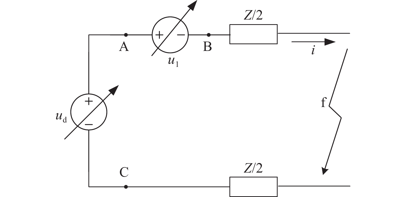
    • 直流微网中含有多种直流电源,有些表现为电压源特性,如基于电压源型换流器接入的交流配网系统、储能系统等,有些表现为电流源特性,如光伏系统[18-19]。直流微网的故障电流主要由电源端提供,其中又以电压源特性的电源提供的故障电流为主。考虑到多数直流微网发生单极故障时故障电流较小,对设备危害较小,故障发生后还可以继续运行一段时间,文章设计的故障电流控制器仅针对极间故障。以基于电压源型换流器接入的交流配网系统为例,在直流侧,交流配网可等效为可调直流电压源,如图1所示。

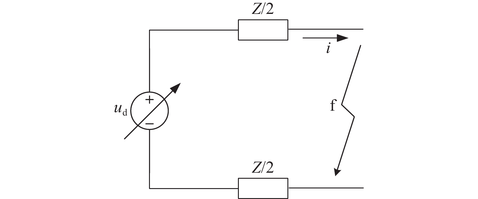
      Figure 1.  DC side equivalent circuit of voltage source converter

      当发生极间故障时,由交流配网提供的故障电流可用下式表示:

      $$ i=u_{\mathrm{d}} /\left(Z+R_{\mathrm{f}}\right) $$ (1)

      式中:

      $ i $ ——电压源型换流器直流侧出口输出电流(kA);

      ${u}_{{\rm{d}}}$ ——交流配网在直流侧的等效电压(kV);

      Z ——故障点至电压源型换流器之间的阻抗(Ω);

      ${R}_{{\rm{f}}}$ ——故障过渡电阻(Ω)。

      可见,故障电流主要取决于等效电压${u}_{\text{d}}$的大小。

      由电压源型换流器的原理可得到以下关系式:

      $$ {U}_{\rm{d}}\text={U}_{\rm{ac}}/m $$ (2)

      式中:

      Ud ——VSC直流侧平均电压(kV);

      Uac ——VSC交流侧电压线电压幅值(kV);

      m ——调制比,且有0< m <1。

      可见,电压源型换流器直流侧电压的调节范围在交流配网线电压幅值往上[20-21]。因此,仅靠调节电压源型换流器的直流侧输出电压,并不能有效控制故障电流。

      倘若将一个反向可控电压源,串联在电压源型换流器的出口处,如图2所示。在正常运行时,控制可控电压源输出电压为0,可不影响微网正常运行;极间故障时,由交流配网提供的故障电流变为如下式(3)。

      Figure 2.  Schematic diagram of fault current controller

      $$ i=({u}_{\rm{d}}-{{u}}_{{1}})/(Z+{R}_{\rm{f}}) $$ (3)

      式中:

      $ {u}_{1} $——反向电压源的输出电压(kV)。

      由此可见,控制故障时可控电压源的输出电压${u}_{1}$的大小,即可任意控制故障电流的大小。

    • 由1.1节分析可见,正常运行时,可控电压源u1的输出电压应接近0以减小串联电压源对直流微网正常运行的影响;故障时,可控电压源u1的输出电压应适当增加。当
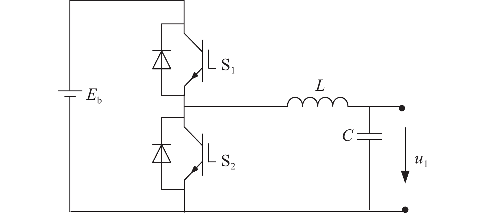
${u}_{1}$=${u}_{\rm{d}}$时,交流电网对故障点提供的故障电流降为0。因此,可控电压源${u}_{\text{1}}$的输出电压应在连续可调的范围0~u之间(u<${u}_{\rm{d}}$)。考虑到微电网的功率双向流动特性,可控电压源${u}_{1}$还应具备电流双向流动能力。

      图3所示的buck-boost电路即可满足上述要求。

      Figure 3.  Structure diagram of fault current controller

      图3中,Eb为储能元件的端电压。当直流微网正常运行时,开关管S1常开,S2常闭,可控电压源
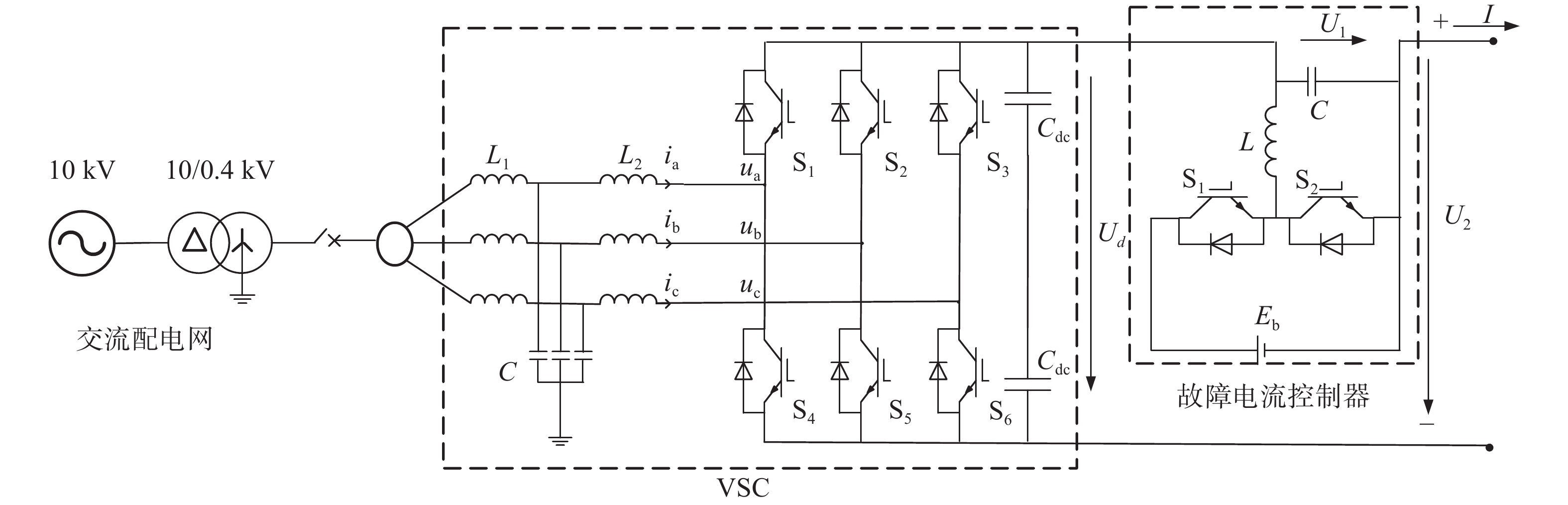
${u}_{1}$的输出电压约为开关管的导通压降,对正常运行影响较小,电感L还可起到降低直流电流纹波的作用。当直流微网发生极间故障时,控制开关管S1和开关管S2的导通占空比,即可调节输出电压${u}_{1}$的大小,从而任意控制故障电流的大小。

      基于电压源型换流器接入直流微网的交流配网系统,串联图3所示的故障电流控制器后,其电路结构如图4所示。在图4所示中,VSC的直流侧满足以下关系式:

      Figure 4.  VSC circuit structure of series fault current controller

      $$ {U}_{2}={U}_{\rm{d}}-{U}_{1} $$ (4)

      式中:

      ${U}_{2}$ ——直流母线电压(kV);

      ${U}_{\rm{d}}$ ——直流侧输出电压平均值(kV);

      ${U}_{1}$ ——故障电流控制器输出电压平均值(kV)。

    • 由上述分析可见,故障电流的控制原理是通过控制输出电压来实现的。因此,为实现故障电流的控制效果,应保证VSC及故障电流控制器均处于可控状态,也就是说VSC及故障电流控制器中的电力电子器件不可处于过流保护停发触发脉冲的状态。考虑到电力电子器件的过流保护一般整定为2~3 pu,因此,故障电流的控制目标不宜大于2 pu。

      倘若故障电流的控制目标过小,如小于1 pu,会使得故障电流过小而使得过流保护无法诊断出故障。因此,故障电流的最低控制目标应与故障诊断及保护整定配合考虑。

    • 故障电流控制器的使用应在充分发挥其效用的同时尽可能降低对系统的不良影响。因此,对于图4所示的故障电流控制器应用场景,正常运行时可控制直流母线电压U2恒为直流微网系统额定电压,使得正常运行时,直流微网侧感受不到故障电流控制器的存在。另外,由式(4)可知,交流电网电压经两级调压(UdU1)后建立微网直流母线电压。因此,当交流侧电网扰动造成直流电压Ud的波动时,经过故障电流控制器的二次调整后,微电网直流母线电压U2的波动将显著降低。

      由于额外增加了装置,将不可避免地产生额外损耗而使得系统总损耗有所增加。

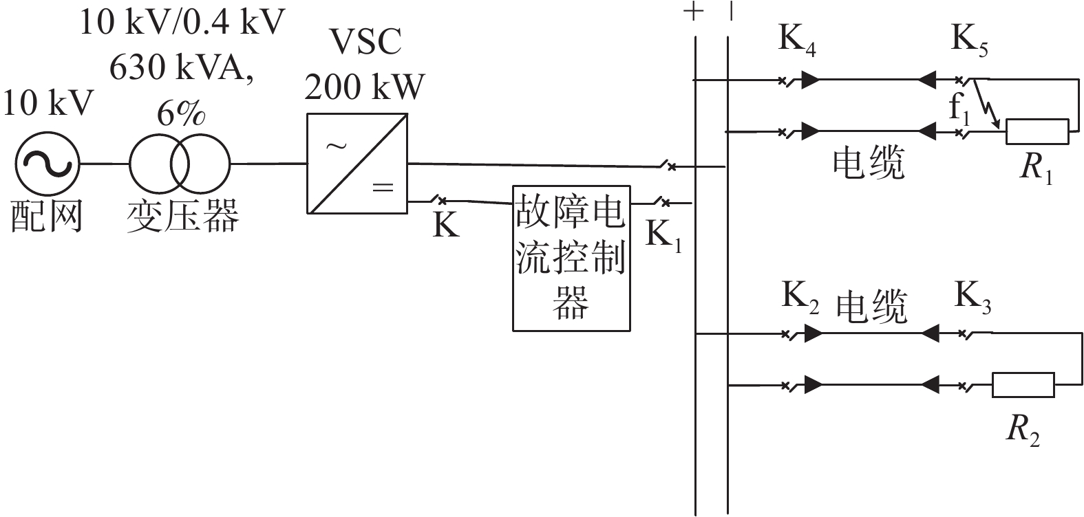
    • 文章仿真分析主要用于验证故障电流控制器的有效性,可采用如图5所示的简化微网结构建立仿真模型。该微电网主要由交流配电网、VSC、故障电流控制器及负载组成,其中,VSC及故障电流控制器的详细电路如图4所示。仿真中设定直流母线极间电压为0.75 kV,R1R2均为10 Ω。0.1 s启动VSC及故障电流控制器的脉冲触发,0.3 s发生极间故障f1。其中,VSC换流器采用定直流电压控制。正常运行时故障电流控制器采用定直流侧母线电压控制,故障下采用定电流控制,控制目标为2倍的额定运行工况电流即0.3 kA。

      Figure 5.  Simplified DC microgrid structure diagram for simulation

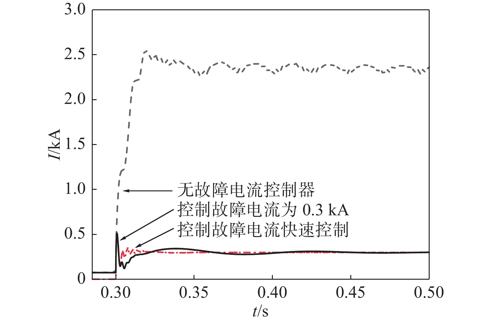
    • 根据图5的仿真结构及参数设定,可得到直流微网在加装故障电流控制器前后的故障电流的波形,如图6所示。

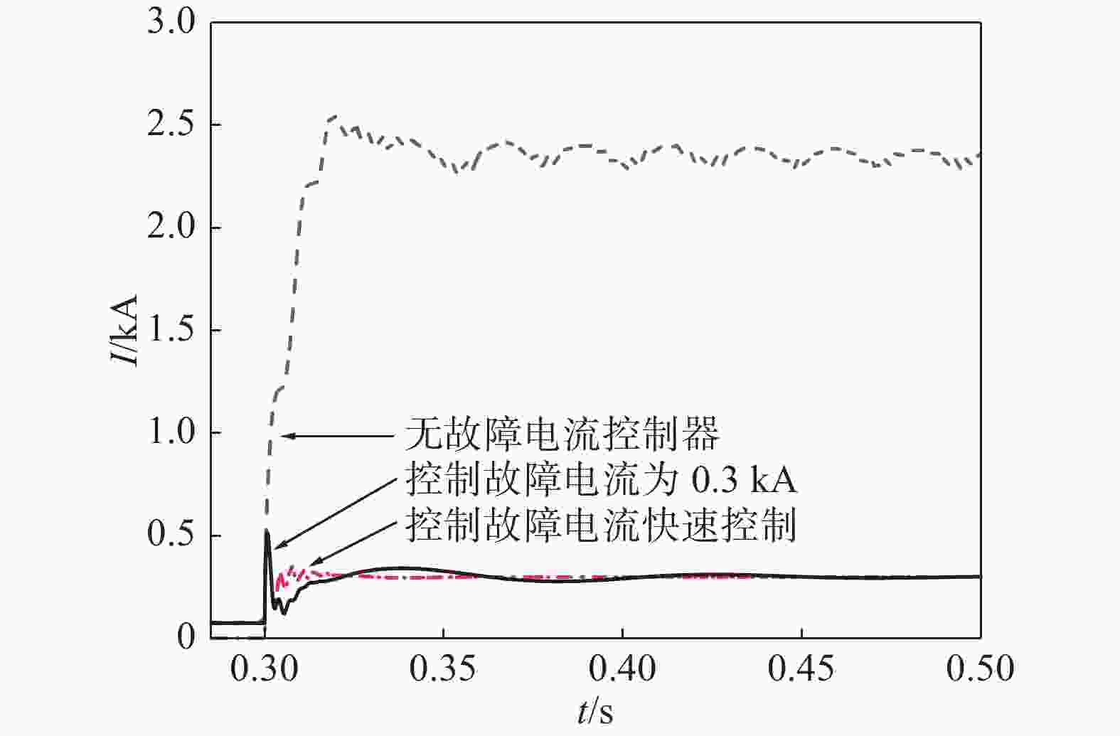
      Figure 6.  Comparison diagram of fault current control effect

      在未添加故障电流控制器时,0.3 s时刻发生f1极间故障,故障电流约在18.8 ms达到最大值2.563 kA,此时VSC所有绝缘栅双极晶体管(Insulated-Gate Bipolar Transistor,IGBT)器件均已触发过流保护,暂停发送触发脉冲。在加装故障电流控制器的作用下,故障电流约在故障后0.7 ms达到峰值0.513 kA,然后随着故障电流控制器的调节作用,最终将故障电流控制在0.3 kA,与控制目标相符。

      比较加装故障电流控制器前后的故障电流波形,可知加装故障电流控制器对故障电流的限制效果如下:

      1)大幅降低故障电流的峰值和稳态值,本算例中故障电流峰值下降了80%,稳态值降低了85%。

      2)大幅缩短较大的故障电流流过系统的时间,本算例中故障电流第一个波峰持续时间不超过2 ms,不会造成断路器的意外跳闸,也不会对系统中的设备造成严重影响。

      3)故障电流稳态值在设备可控范围内可调可控。

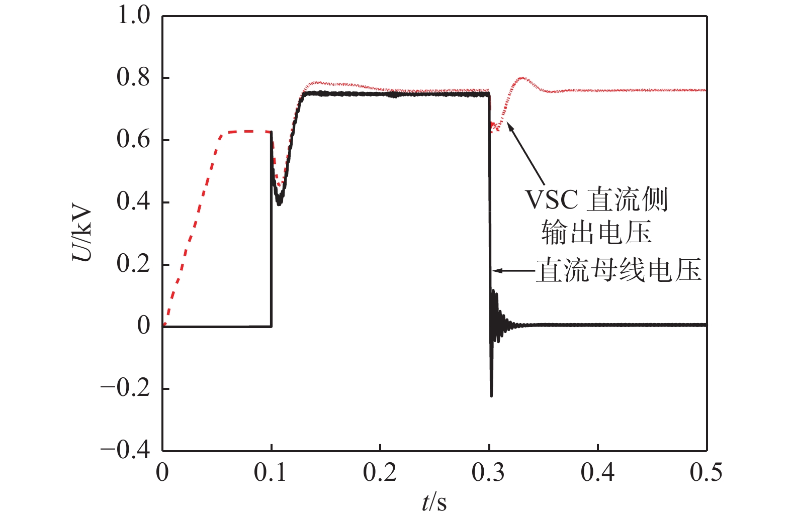
    • 根据图5的仿真结构及参数设定,可得到在加装故障电流控制器后的VSC直流侧输出电压波形及微网直流母线电压波形,如图7所示。

      Figure 7.  Voltage waveform diagram of VSC DC side and DC bus

      图7给出加装故障电流控制器后,VSC直流侧输出电压波形及微网直流母线电压波形。从0时刻起,VSC直流端口电容开始充电,VSC直流侧输出电压逐渐上升,直到上升至不控整流输出电压值。0.1 s时刻启动VSC脉冲触发,VSC输出电压经过短暂调整后稳定至控制目标值。0.3 s时刻发生极间短路,VSC输出端受到故障影响产生短时电压波动,随后稳定。

      由于正常运行时要求故障电流控制器的输出电压接近于0,因此,在故障电流控制器启动之前,故障电流控制器的出口电容器不应充电至较高电压,否则故障电流控制器启动时,端口电容器放电将产生较大的放电电流。如图3中,电容器通过电感、IGBT器件S2放电,使得S2中流过较大的冲击电流,可能造成S2损坏。为防止此现象,仿真中假设在故障电流控制器启动前开关K断开。因此,在启动触发脉冲前,直流母线电压为0。启动触发脉冲后,故障电流控制器为电压控制模式,在VSC输出电压的基础上进一步调节电压,使得直流母线电压较VSC输出电压更快稳定至额定电压0.75 kV。极间故障发生后,故障电流控制器经过故障诊断后切换为电流控制模式,故障电流控制器输出电压迅速上升,直流母线电压迅速下降,以实现故障电流的有效控制。

      由此可见,故障电流的峰值电流与故障诊断速度密切相关,在故障电流控制器诊断出故障且进行控制模式切换后,才具备故障电流控制功能。
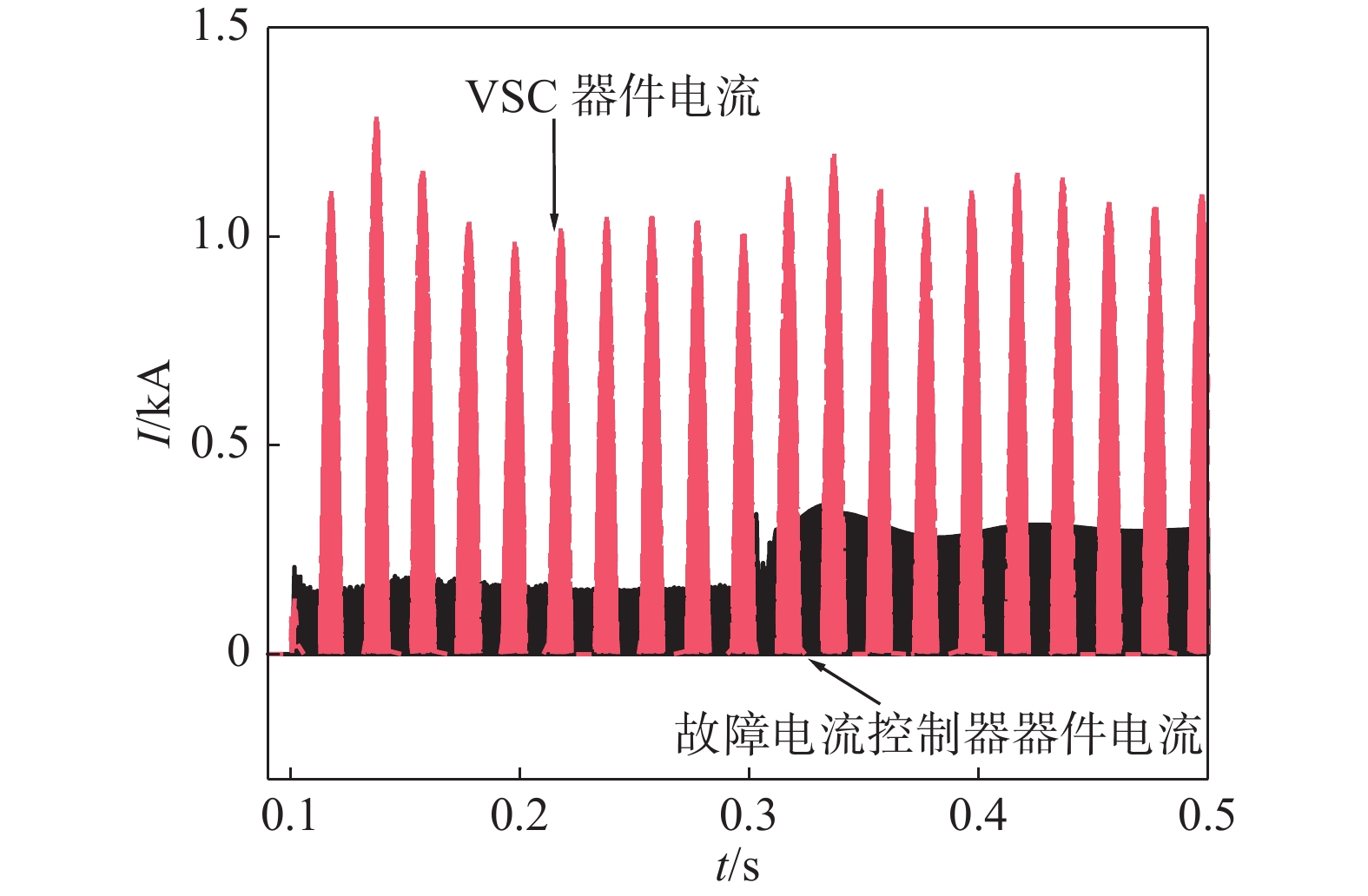
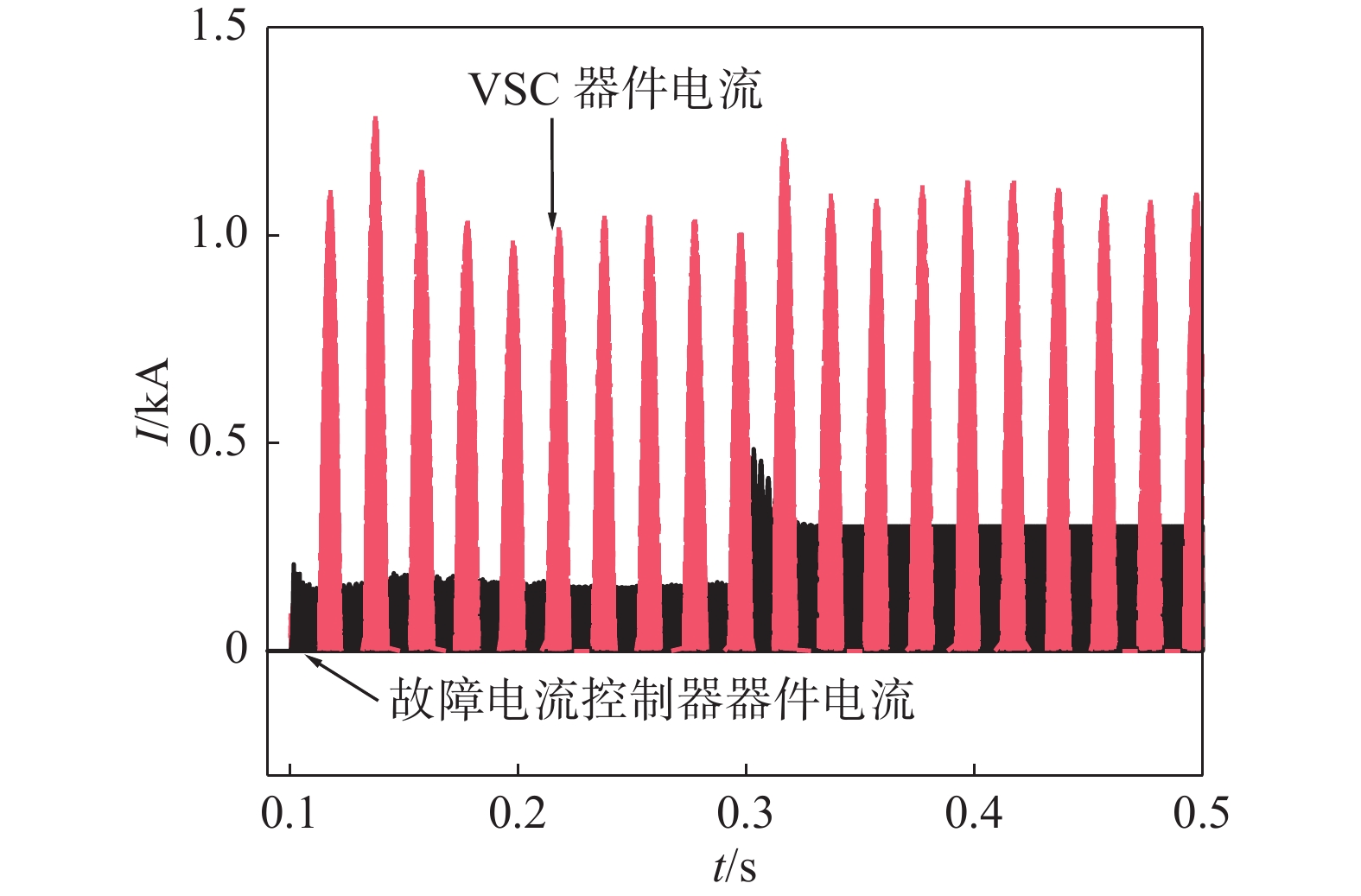
    • 图8图9给出了VSC及故障电流控制器中IGBT器件上流过的电流。其中,故障电流的调节速度与故障电流控制器的控制参数等有关。故障电流调节快慢的效果对比见图6所示。快速调节时,故障电流可快速稳定至控制目标0.3 kA,但结合图8图9可见,快速调节时,故障电流控制器中的IGBT器件在电流调节初期流过的电流显著大于稳态时的电流。由此可见,快速调节的故障电流控制器在器件选型时需留有更大的余量,否则快速调节的故障电流控制器其电流控制范围应相应有所降低。对比图8图9可见,故障电流的调节速度对VSC的器件电流影响不大。且故障发生后,VSC器件上流过的电流并未成倍增加,不会触发器件过流保护。

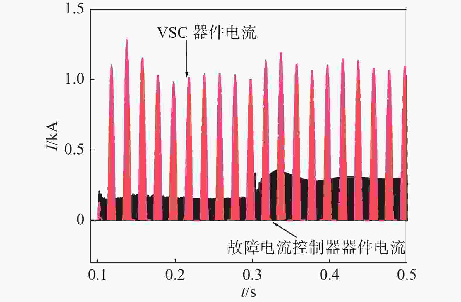
      Figure 8.  Current flowing on IGBT device in VSC and fault current controller (Fault current regulation speed is slow)

      Figure 9.  Current flowing on IGBT device in VSC and fault current controller (Fast regulation of fault current)

    • 针对直流微网阻抗小、极间故障电流大的特点,文章提出了一种基于可控反向电压源精确控制故障电流的方法。首先对其工作原理和基本结构进行分析,其次对基于反向电压源的故障电流控制器对微网正常运行的影响进行分析,最后通过仿真验证,探讨了故障电流控制器的故障电流控制范围。仿真显示,文章提出的故障电流控制器可大幅降低故障电流,并可实现精确控制,使得故障前后系统均处于可控状态而不会闭锁保护。在稳态运行时,故障电流控制器还可辅助VSC起到进一步稳定直流母线电压的作用。为配合继电保护装置正常动作,同时避免VSC触发过流保护闭锁,建议故障电流控制范围设置在1~2 pu之间。

Reference (21)

Catalog

    /

    DownLoad:  Full-Size Img  PowerPoint
    Return
    Return